


 Loading...
User Manual
MULTIGATE PRO XR4400
Reference-Class 4-Channel Expander/Gate

2 MULTIGATE PRO XR4400 User Manual
Table of Contents
Important Safety Instructions....................................... |
3 |
|
Legal Disclaimer.............................................................. |
3 |
|
Limited warranty............................................................ |
3 |
|
1. Introduction................................................................ |
4 |
|
1.1 Technical background........................................................ |
4 |
|
2. The Design Concept................................................... |
6 |
|
2.1 High quality components and design......................... |
6 |
|
2.2 |
Inputs and outputs............................................................. |
6 |
3. Installation.................................................................. |
6 |
|
3.1 Rack mounting..................................................................... |
6 |
|
3.2 |
Mains voltage....................................................................... |
6 |
3.3 |
Audio connections............................................................. |
6 |
4. Controls....................................................................... |
7 |
|
4.1 The front panel control elements.................................. |
7 |
|
4.2 |
The rear panel elements................................................... |
8 |
5. Technical Background................................................ |
8 |
|
5.1 EXPANDER mode................................................................. |
8 |
|
5.2 |
Interactive control functions.......................................... |
8 |
5.3 |
FLEXLINK function............................................................ |
10 |
5.4 The SIDECHAIN filter........................................................ |
10 |
|
6. Applications.............................................................. |
10 |
|
6.1 Basic setting........................................................................ |
10 |
|
6.2 |
Proper positioning of microphones........................... |
11 |
6.3 |
Applications ....................................................................... |
12 |
7. Specifications............................................................ |
12 |
|
3 MULTIGATE PRO XR4400 User Manual
Important Safety
Instructions
Terminals marked with this symbol carry electrical current of sufficient magnitude to constitute risk of electric shock.
Use only high-quality professional speaker cables with ¼" TS or twist-locking plugs pre-installed. All other installation or modification should be performed only by qualified personnel.
This symbol, wherever it appears,
alerts you to the presence of uninsulated dangerous voltage inside the
enclosure - voltage that may be sufficient to constitute a risk of shock.
This symbol, wherever it appears, alerts you to important operating and maintenance instructions in the
accompanying literature. Please read the manual.
Caution
To reduce the risk of electric shock, do not remove the top cover (or the rear section).
No user serviceable parts inside. Refer servicing to qualified personnel.
Caution
To reduce the risk of fire or electric shock, do not expose this appliance to rain and moisture. The apparatus shall not be exposed to dripping
or splashing liquids and no objects filled with liquids, such as vases, shall be placed on the apparatus.
Caution
These service instructions are for use by qualified service personnel only.
To reduce the risk of electric shock do not perform any servicing other than that contained in the operation instructions. Repairs have to be performed by qualified service personnel.
1.Read these instructions.
2.Keep these instructions.
3.Heed all warnings.
4.Follow all instructions.
5.Do not use this apparatus near water.
6.Clean only with dry cloth.
7.Do not block any ventilation openings. Install in accordance with the manufacturer’s instructions.
8.Do not install near any heat sources such as radiators, heat registers, stoves, or other apparatus (including amplifiers) that produce heat.
9.Do not defeat the safety purpose of the polarized or grounding-type plug. A polarized plug has two blades with one wider than the other. A grounding-type plug has two blades and a third grounding prong. The wide
blade or the third prong are provided for your safety. If the provided plug does not fit into your outlet, consult an electrician for replacement of the obsolete outlet.
10.Protect the power cord from being walked on or pinched particularly at plugs, convenience receptacles, and the point where they exit from the apparatus.
11.Use only attachments/accessories specified by
the manufacturer.
12. Use only with the cart, stand, tripod, bracket,
or table specified by the
manufacturer, or sold with the apparatus. When a cart is used, use caution when
moving the cart/apparatus combination to avoid
injury from tip-over.
13.Unplug this apparatus during lightning storms or when unused for long periods of time.
14.Refer all servicing to qualified service personnel. Servicing is required when the apparatus has been damaged in any way, such as power supply cord or plug is damaged, liquid has been spilled or objects have fallen into the apparatus, the apparatus has been exposed
to rain or moisture, does not operate normally, or has been dropped.
15.The apparatus shall be connected to a MAINS socket outlet with a protective earthing connection.
16.Where the MAINS plug or an appliance coupler is used as the disconnect device, the disconnect device shall remain readily operable.
LEGAL DISCLAIMER
TECHNICAL SPECIFICATIONS AND APPEARANCES ARE SUBJECT TO CHANGE WITHOUT NOTICE AND ACCURACY IS NOT GUARANTEED. BEHRINGER, KLARK TEKNIK, MIDAS, BUGERA, AND TURBOSOUND
ARE PART OF THE MUSIC GROUP (MUSIC-GROUP.COM). ALL TRADEMARKS ARE THE PROPERTY OF THEIR RESPECTIVE OWNERS. MUSIC GROUP ACCEPTS NO LIABILITY FOR ANY LOSS WHICH MAY BE SUFFERED BY ANY PERSON WHO RELIES EITHER WHOLLY OR
IN PART UPON ANY DESCRIPTION, PHOTOGRAPH OR STATEMENT CONTAINED HEREIN. COLORS AND
SPECIFICATIONS MAY VARY FROM ACTUAL PRODUCT. MUSIC GROUP PRODUCTS ARE SOLD THROUGH AUTHORIZED FULLFILLERS AND RESELLERS ONLY. FULLFILLERS AND RESELLERS ARE NOT AGENTS OF MUSIC GROUP AND HAVE ABSOLUTELY NO AUTHORITY
TO BIND MUSIC GROUP BY ANY EXPRESS OR IMPLIED
UNDERTAKING OR REPRESENTATION. THIS MANUAL IS COPYRIGHTED. NO PART OF THIS MANUAL MAY BE REPRODUCED OR TRANSMITTED IN ANY FORM OR BY ANY MEANS, ELECTRONIC OR MECHANICAL,
INCLUDING PHOTOCOPYING AND RECORDING OF ANY KIND, FOR ANY PURPOSE, WITHOUT THE EXPRESS WRITTEN PERMISSION OF MUSIC GROUP IP LTD.
ALL RIGHTS RESERVED.
© 2013 MUSIC Group IP Ltd.
Trident Chambers, Wickhams Cay, P.O. Box 146, Road Town, Tortola, British Virgin Islands
LIMITED WARRANTY
For the applicable warranty terms and conditions and additional information regarding MUSIC Group’s
Limited Warranty, please see complete details online at www.music-group.com/warranty.

4MULTIGATE PRO XR4400 User Manual
1.Introduction
With the BEHRINGER MULTIGATE PRO you purchased a dynamics processor of the high-end class designed to meet highest requirements: professional recording, broadcast and television studios, CD and digital production facilities,
etc. Its complete range of features and innovative circuit topology make the MULTIGATE PRO an all-purpose device for reducing noise in audio recordings, for automatically muting stage mics, expanding the dynamic
range of compressed recordings, improving the signal-to-noise ratio of noisy communications systems and for producing special effects, etc.
Future-oriented BEHRINGER technology
Our MULTIGATE range of devices has been a hit ever since we introduced our first model several years ago. This expander/gate is based on many years of experience and findings in psychoacoustics and is used throughout the world in renowned studios, sound reinforcement systems as well as in broadcast and television studios.
It was a real challenge to improve the well-known MULTIGATE even further, and we are proud of our success. Compared to its predecessor models,
the MULTIGATE PRO not only has additional features, but also comes with dramatically improved functionalities. For example, it now has a parametric filter enabling you to accurately set the trigger frequencies, while the FlexLink system allows for great flexibility when linking the device’s individual channels in a master/slave configuration.
Basically, quadruple gates are not a new invention. However, packing four simple noise gates into one enclosures usually means a compromise in terms of ease
of operation and functionality. Too many control elements make such a device impossible to handle, and if you sacrifice crucial functions for the sake of easy operation, the range of useful applications is restricted considerably.
The BEHRINGER MULTIGATE PRO is a quadruple expander/gate with a maximum of functionalities and can still be operated conveniently. Interactive functions make it easy and efficient to specifically process any kind of program material, while the need for “adjustment work” has been reduced drastically. Each of the MULTIGATE PRO’s four sections comprises an ultra-fast gate, a programdependent expander, a filter section and high-precision meters indicating both threshold point and gain reduction.
The IAC circuit (Interactive Attack Control)
One of the MULTIGATE PRO’s most outstanding features is the program-dependent control of attack times. The new IAC circuit (Interactive Attack Control) analyzes the program material to calculate the attack time by way of interaction, so that the hold/release process is triggered automatically depending on the program, which is why the MULTIGATE PRO does not need a dedicated attack control.
Switchable gate/expander function
Another highlight of the MULTIGATE PRO is the switchable operating mode of gate and expander. With the MODE function off, the MULTIGATE PRO works in gate mode using an extremely fast attack time to gate all kinds of drum and synthesizer sounds, without cutting their percussive edge.
In expander mode the device analyzes the shape and dynamic contents of the input signal to calculate the control time parameters. It thus works as an
interactive expander that adapts automatically to the program signal. The result: guitar sounds, vocals and complex mix signals can be “cleaned” without audible clicks, breathing or other detrimental effects. Additionally, you can freely expand any type of program material in its dynamic range.
Side-chain filter section
When several microphones are used, for example to pick up a drum set, crosstalk between microphones can lead to unwanted triggering of the gate. The built-in parametric sidechain filter of the MULTIGATE PRO allows the user to accurately
select the frequencies causing the trouble, so that the device responds to these frequencies only. The monitor function can be used to pre-monitor the filter, making it easier to adapt the circuitry to the acoustic properties of the program material.
FlexLink system
An innovative couple function gives you great flexibility to synchronize the expander/gate sections in a master/slave configuration.
◊The following operational manual will introduce you to the BEHRINGER MULTIGATE PRO and its various functions. After reading the manual carefully, make sure it is always on hand for future reference.
1.1 Technical background
By employing current modern analog technology it is possible to manufacture audio equipment with a dynamic range of up to 130 dB. In contrast to analog techniques, the dynamic range of digital equipment is approximately 25 dB less. With conventional record and tape recorder technology, as well as broadcasting, this value is further reduced. Generally, dynamic restrictions are due to noisy storage in transmission media and also the maximum headroom of these systems.
1.1.1 Noise as a physical phenomenon
All electrical components produce a certain level of inherent noise.
Current flowing through a conductor leads to uncontrolled random electron movements. For statistical reasons, this produces frequencies within the whole audio spectrum. If these currents are highly amplified, the result will be
perceived as noise. Since all frequencies are equally affected, we term this white noise. It is fairly obvious that electronics cannot function without components. Even if special low-noise components are used, a certain degree of basic noise cannot be avoided.
This effect is similar when replaying a tape. The non-directional magnetic particles passing the replay head can also cause uncontrolled currents and voltages. The resulting sound of the various frequencies is heard as noise.
Even the best possible tape biasing can “only” provide signal-to-noise ratios of about 70 dB, which is not acceptable today since the demands of listeners have increased. Due to the laws of physics, improving the design of the magnetic carrier is impossible using conventional means.
1.1.2 What are audio dynamics?
A remarkable feature of the human ear is that it can detect the most wide ranging amplitude changes—from the slightest whisper to the deafening roar of a jet-plane. If one tried to record or reproduce this wide spectrum of sound with the help of amplifiers, cassette recorders, records or even digital recorders (CD, DAT etc.), one would immediately be restricted by the physical limitations of electronic and acoustic sound reproduction technology.
The usable dynamic range of electro-acoustic equipment is limited as much at the low end as at the high end. The thermal noise of the electrons in the components results in an audible basic noise floor and thus represents the bottom limit of the transmission range. The upper limit is determined by the levels of the internal operating voltages; if they are exceeded, audible signal distortion is the result. Although in theory, the usable dynamic range sits between these two limits, it is considerably smaller in practice, since a certain
reserve must be maintained to avoid distortion of the audio signal if sudden level peaks occur. Technically speaking, we refer to this reserve as “headroom”— usually this is about 10 - 20 dB. A reduction of the operating level would allow for greater headroom, i.e. the risk of signal distortion due to level peaks would be reduced. However, at the same time, the basic noise floor of the program material would be increased considerably.
5 MULTIGATE PRO XR4400 User Manual
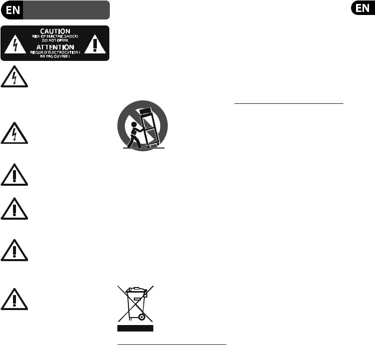
P/dB |
|
|
|
|
|
140 |
|
|
|
|
|
120 |
|
|
|
|
|
100 |
|
|
|
|
|
80 |
Microphone Amplifier |
|
|
|
|
60 |
Power Amplifier |
|
|
|
|
40 |
Tape Radio |
|
Cassette Recorder |
||
Ear |
Radio |
Fig. 1.1: The dynamic range capabilities of various devices
It is therefore useful to keep the operating level as high as possible without risking signal distortion in order to achieve optimum transmission quality.
It is possible to further improve the transmission quality by constantly monitoring the program material with the aid of a volume fader, which manually levels the material. During low passages the gain is increased, during loud passages the gain is reduced. Of course it is fairly obvious that this kind of manual control is rather restrictive; it is difficult to detect signal peaks and it is almost impossible to level them out. Manual control is simply not fast enough to be satisfactory.
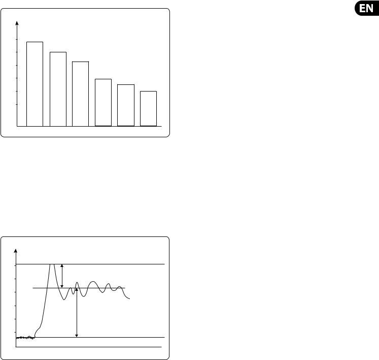
P/dB
+20 |
Clipping |
|
|
0 |
Headroom |
|
|
-20 |
Operating level |
|
-40
Effective SNR
-60
-80
Noise floor t 
Fig. 1.2: The interactive relationship between the operating level and the headroom
The need therefore arises for a fast acting automatic gain control system which will constantly monitor the signals and which will always adjust the gain to maximize the signal-to-noise ratio without incurring signal distortion. This device is called a compressor or limiter.
1.1.3 Compressors/Limiters
By measuring the dynamic range of musical instruments in live recording situations, you will find that extreme amplitudes occur which often lead to overload in subsequent signal processing equipment. Especially in broadcasting and record cutting techniques, these signal peaks can lead to heavy distortion. To avoid this kind of distortion or, for example, to avoid loudspeakers being damaged by overload, Compressors or Limiters are used.
The principal function used in these devices is dependent on an automatic gain control as mentioned in the previous section, which reduces the amplitude of loud passages and therefore restricts the original dynamics to a desired range. This application is particularly useful in microphone recording techniques,
to compensate for level changes which are caused by varying microphone distances. Although compressors and limiters perform similar tasks, one essential point makes them different: Limiters abruptly limit the signal above a certain level, while compressors control the signal “gently” over a wider range.
A limiter continuously monitors the signal and intervenes as soon as the level exceeds a user-adjustable threshold. Any signal exceeding this threshold will be immediately returned to the adjusted level.
A compressor also monitors the program material continuously and has a certain threshold level. With compression, in contrast to the action of a limiter, signals are not reduced in level abruptly once the threshold has been exceeded, but are returned to the threshold gradually. The signal is reduced in gain, relative to the amount the signal exceeds this point.
Generally, threshold levels for compressors are set below the normal operating level to allow for the upper dynamics to be musically compressed. For limiters, the threshold point is set above the normal operating level in order to provide reliable signal limiting, to protect subsequent equipment from signal overload.
1.1.4 Expanders/Noise gates
Audio, in general, is only as good as the source from which it was derived. The dynamic range of signals will often be restricted by noise.
Synthesizers, effects devices, guitar pickups, amplifiers etc. generally produce a high level of noise, hum or other ambient background hiss, which can disturb the quality of the program material.
Normally these noises are inaudible if the level of the desired signal lies significantly above the level of the noise. This perception by the ear is based on the “masking” effect: noise will be masked and thus becomes inaudible as soon as considerably louder sound signals in the same frequency band are added. Nevertheless, the further the level that the desired signal decreases, the more the noise floor becomes a disturbing factor. Expanders or noise gates offer a solution for this problem: these devices attenuate signals when their amplitudes drop, thereby fading out the background noise. Relying on this method,
gain controlling amplifiers, like expanders, can extend the dynamic range of a signal and are therefore the opposite of a compressor.
In practice, it is shown that an expansion over the entire dynamic range is not desired. With an expansion ratio of 1:5 and a processed dynamic range of 30 dB, an output dynamic range of 150 dB will be the result, exceeding all subsequent signal processors, as well as human hearing. Therefore, the amplitude control is restricted to signals whose levels are below a certain threshold. Signals above this threshold pass through the unit unchanged. Due to the continuous attenuation of the signals below this threshold, this kind of expansion is termed “downward” expansion.
The noise gate is the simplest form of an expander: in contrast to the expander, which continuously attenuates a signal below the threshold, the noise gate cuts off the signal abruptly. In most applications this method is not very useful, since the on/off transition is too drastic. The onset of a simple gate function appears very obvious and unnatural. To achieve inaudible processing of the program material, it is necessary to be able to control the signal’s envelope parameters.
Loading...