


X1204USB
ENGLISH
User Manual
XENYX
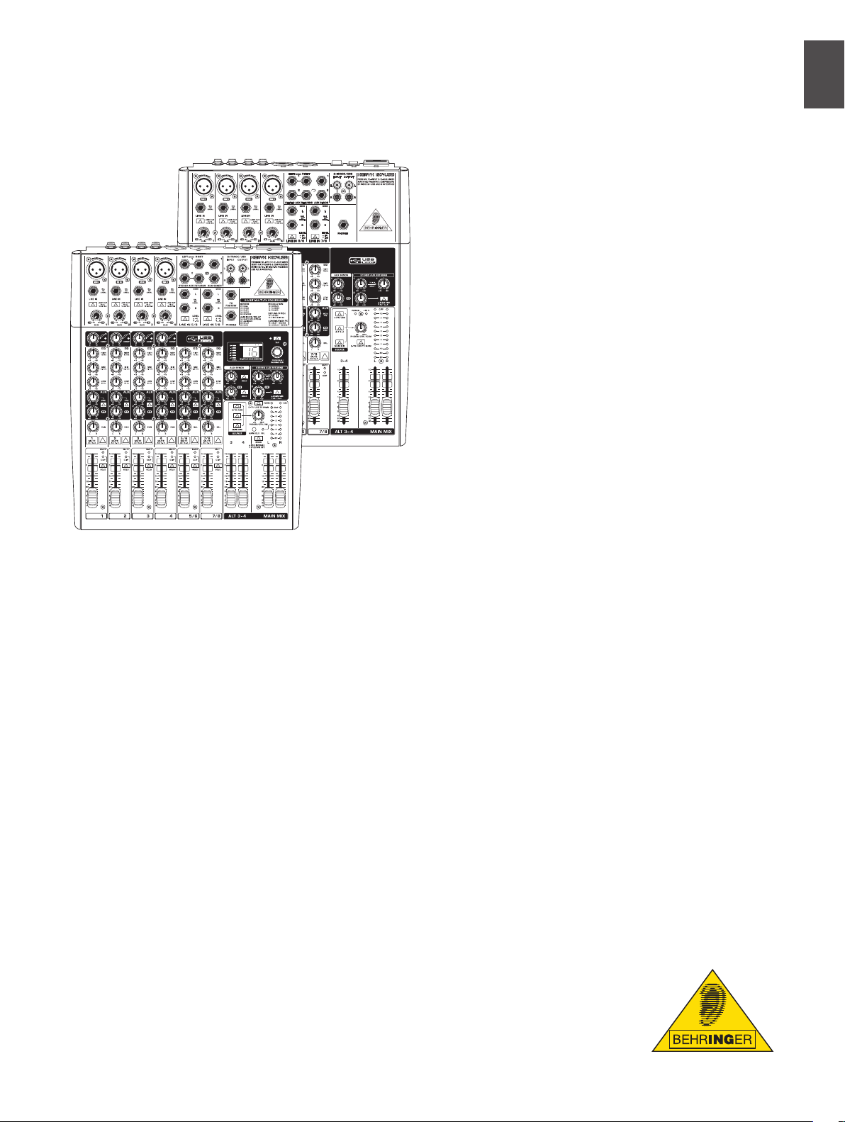
1204US B/ X120 4USB
Premium 12-Input 2/2-Bus
Mixer with XENYX Mic
Preamps & Compressors,
British EQs, USB/Audio
Interface and energyXT2.5
Compact BEHRINGER Edition
Music Production Software
Thank you
Congratulations! In purchasing the BEHRINGER XENYX you
have acquired a mixer whose small size belies its incredible
versatility and audio performance.
The XENYX Series represents a milestone in the
development of mixing console technology. With the
new XENYX microphone preamps including phantom
power as an option, balanced line inputs and a powerful
eects section, the mixing consoles in the XENYX Series
are optimally equipped for live and studio applications.
Owing to state-of-the-art circuitry your XENYX console
produces a warm analog sound that is unrivalled. With the
addition of the latest digital technology these best-in-class
consoles combine the advantages of both analog and digital
technology.
Table of Contents
Thank you ..................................................................... 1
Important Safety Instructions ................................... 2
1. Introduction ............................................................ 3
1.1 General mixing console functions .......................................3
1.2 The user’s manual .........................................................................3
1.3 Before you get started ................................................................3
2. Control Elements And Connectors ....................... 4
2.1 Mono channels ..............................................................................4
2.2 Stereo channels .............................................................................5
2.3 Connector panel and main section ......................................6
2.4 Rear view of X1204USB/1204USB .........................................9
3. Digital Eects Processor ...................................... 10
4. Installation ............................................................. 10
4.1 Rack mounting ...........................................................................10
4.2 Cable connections ....................................................................10
5. Specications ........................................................12
Limited Warranty ...................................................... 14
Legal Disclaimer ........................................................ 15

ENGLISH
XENYX 1204USB/X1204USB User Manual
2
ENGLISH
XENYX 1204USB/X1204USB User Manual
3
*
Terminals marked with this symbol carry electrical current of
su cient magnitude to constitute risk of electric shock. Use only
high-quality commercially-available speaker cables with ¼" TS
plugs pre-installed. All other installation or modi cation should be
performed only by quali ed personnel.
*
This symbol, wherever it appears, alerts you to the presence of
uninsulated dangerous voltage inside the enclosure - voltage that
may be su cient to constitute a risk of shock.
!
This symbol, wherever it appears, alerts you to important operating
and maintenance instructions in the accompanying literature.
Please read the manual.
Caution !
To reduce the risk of electric shock, do not remove the top cover
(or the rear section). No user serviceable parts inside. Refer servicing
to quali ed personnel.
Caution !
To reduce the risk of re or electric shock, do not expose this
appliance to rain and moisture. The apparatus shall not be exposed
to dripping or splashing liquids and no objects lled with liquids,
such as vases, shall be placed on the apparatus.
Caution !
These service instructions are for use by quali ed service personnel
only. To reduce the risk of electric shock do not perform any
servicing other than that contained in the operation instructions.
Repairs have to be performed by quali ed service personnel.
Read these instructions.
[1]
Keep these instructions.[2]
Heed all warnings.[3]
Follow all instructions.[4]
Do not use this apparatus near water.[5]
Clean only with dry cloth.[6]
Do not block any ventilation openings. Install in accordance [7]
with the manufacturer’s instructions.
Do not install near any heat sources such as radiators, heat
[8]
registers, stoves, or other apparatus (including ampli ers) that
produce heat.
Do not defeat the safety purpose of the polarized or grounding-
[9]
type plug. A polarized plug has two blades with one wider
than the other. A grounding-type plug has two blades and
a third grounding prong. The wide blade or the third prong
are provided for your safety. If the provided plug does not t
into your outlet, consult an electrician for replacement of the
obsolete outlet.
Protect the power cord from being walked on or pinched
[10]
particularly at plugs, convenience receptacles, and the point
where they exit from the apparatus.
Use only attachments/accessories speci ed by
[11]
the manufacturer.
Use only with the cart, stand, tripod, bracket,
[12]
or table speci ed by the manufacturer, or
sold with the apparatus. When a cart is used,
use caution when moving the cart/apparatus
combination to avoid injury from tip-over.
Unplug this apparatus during lightning
[13]
storms or when unused for long periods of time.
Refer all servicing to quali ed service personnel. Servicing is
[14]
required when the apparatus has been damaged in any way,
such as power supply cord or plug is damaged, liquid has been
spilled or objects have fallen into the apparatus, the apparatus
has been exposed to rain or moisture, does not operate
normally, or has been dropped.
The apparatus shall be connected to a MAINS socket outlet
[15]
with a protective earthing connection.
Where the MAINS plug or an appliance coupler is used as the
[16]
disconnect device, the disconnect device shall remain
readily operable.
EN
Important Safety Instructions
Introduction1.
CAUTION! !
We should like to draw your attention to the fact that extreme
volumes may damage your hearing and/or your headphones or
loudspeakers. Turn the MAIN MIX faders and phones control in the
main section fully down before you switch on the unit. Always be
careful to set the appropriate volume.
General mixing console functions 1.1
A mixing console fulls three main functions:
Signal processing• : Preamplication, level adjustment,
mixing of eects, frequency equalization.
Signal distribution• : Summing of signals to the
aux sends for eects processing and monitor mix,
distribution to one or several recording tracks, power
amp(s), control room and 2-track outputs.
Mix• : Setting the volume level, frequency distribution
and positioning of the individual signals in the stereo
eld, level control of the total mix to match the recording
devices/crossover/power amplier(s). All other mixer
functions can be included in this main function.
The interface of BEHRINGER mixing consoles is optimized
for these tasks enabling you to easily keep track of the
signal path.
The user’s manual1.2
The user’s manual is designed to give you both an overview
of the controls, as well as detailed information on how to use
them. In order to help you understand the links between
the controls, we have arranged them in groups according
to their function. If you need to know more about specic
issues, please visit our website at http://www.behringer.com,
where you’ll nd explanations of e.g. eects and dynamics
applications.
Before you get started1.3
Shipment1.3.1
Your mixing console was carefully packed in the factory to
guarantee safe transport. Nevertheless, we recommend that
you carefully examine the packaging and its contents for any
signs of physical damage, which may have occurred during
transit.
If the unit is damaged, please do NOT return it to us, ◊
but notify your dealer and the shipping company
immediately, otherwise claims for damage or
replacement may not be granted.
Initial operation1.3.2
Be sure that there is enough space around the unit for
cooling purposes and to avoid over-heating please do not
place your mixing console on high-temperature devices
such as radiators or power amps. The console is connected
to the mains via the supplied cable. The console meets
the required safety standards. Blown fuses must only be
replaced by fuses of the same type and rating.
Please note that all units must be properly grounded. ◊
For your own safety, you should never remove any
ground connectors from electrical devices or power
cables, or render them in operative.
Please ensure that only qualied people install and ◊
operate the mixing console. During installation and
operation, the user must have sucient electrical
contact to earth, otherwise electrostatic discharges
might aect the operation of the unit.
Online registration1.3.3
Please do remember to register your new BEHRINGER
equipment right after your purchase by visiting www.
behringer.com (alternatively www.behringer.de) and kindly
read the terms and conditions of our warranty carefully.
Should your BEHRINGER product malfunction, our goal
is to have it repaired as quickly as possible. To arrange for
warranty service, please contact the retailer from whom the
equipment was purchased. Should your BEHRINGER dealer
not be located in your vicinity, you may directly contact
one of our subsidiaries. Corresponding contact information
is included in the original equipment packaging (Global
Contact Information/European Contact Information). Should
your country not be listed, please contact the distributor
nearest you. A list of distributors can be found in the support
area of our website (www.behringer.com).
Registering your purchase and equipment with us helps us
process your repair claims quicker and more eciently.
Thank you for your cooperation!
ENGLISH
XENYX 1204USB/X1204USB User Manual
4
ENGLISH
XENYX 1204USB/X1204USB User Manual
5
Control Elements and 2.
Connectors
This chapter describes the various control elements of your
mixing console. All controls, switches and connectors will be
discussed in detail.
Mono channels2.1
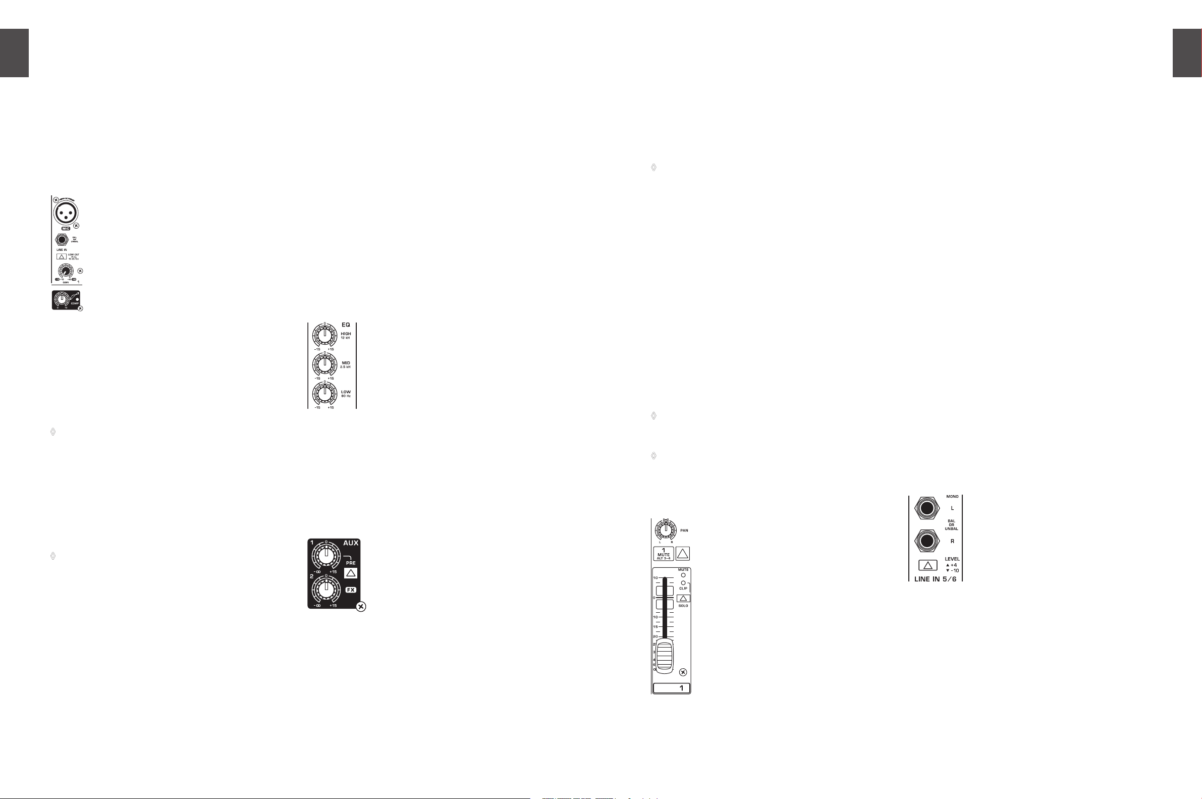
Microphone and line inputs 2.1.1
Fig. 2.1: Connectors and controls of mic/line inputs
MIC
Each mono input channel oers a balanced microphone
input via the XLR connector and also features switchable
+48 V phantom power supply for condenser microphones.
The XENYX preamps provide undistorted and noise-free gain
as is typically known only from costly outboard preamps.
Please mute your playback system before you activate ◊
the phantom power supply to prevent switch-on
thumps being directed to your loud speakers. Please
also note the instructions in chapter 2.4.2 “Voltage
supply, phantom power and fuse”.
LINE IN
Each mono input also features a balanced line input on a
¼" connector. Unbalanced devices (mono jacks) can also be
connected to these inputs.
Please remember that you can only use either the ◊
microphone or the line input of a channel at any one
time. You can never use both simultaneously!
LOW CUT
The mono channels of the mixing consoles have a
high-slope LOW CUT lter for eliminating unwanted
low-frequency signal components (75 Hz, 18 dB/octave).
GAIN
Use the TRIM control to adjust the input gain. This control
should always be turned fully counterclockwise whenever
you connect or disconnect a signal source to one of the
inputs.
COMPRESSOR
Each mono channel features a built-in compressor which
lowers the dynamic range of the signal and increases its
perceived loudness. The loud peaks are squashed down
and the quiet sections are boosted.
Turn the COMP knob clockwise to add more compression
eect. The adjacent LED with light when the eect is
engaged.
Equalizer2.1.2
All mono input channels include a 3-band equalizer. All
bands provide boost or cut of up to 15 dB. In the central
position, the equalizer is inactive.
The circuitry of the British EQs is based on the technology
used in the best-known top-of-the-line consoles and
providing a warm sound without any unwanted side eects.
The result are extremely musical equalizers which, unlike
simple equalizers, cause no side eects such as phase
shifting or bandwidth limitation, even with extreme gain
settings of ±15 dB.
Fig. 2.2: The equalizer of the input channels
The upper (HI) and the lower band (LO) are shelving lters
that increase or decrease all frequencies above or below
their cut-o frequency. The cut-o frequencies of the upper
and lower band are 12 kHz and 80 Hz respectively. The mid
band is congured as a peak lter with a center frequency
of 2.5 kHz.
Aux sends2.1.3
Fig. 2.3: The AUX SEND controls in the channel strips
Aux sends take signals via a control from one or more
channels and sum these signals to a so-called bus. This bus
signal is sent to an aux send connector and then routed,
for example, to an active monitor speaker or an external
eects device. The return from an external eect can then be
brought back into the console via the aux return connectors.
For situations which require eects processing, the aux
sends are usually switched post-fader so that the eects
volume in a channel corresponds to the position of the
channel fader. If this were not the case, the eects signal
of the channel would remain audible even when the fader
is turned to zero. When setting up a monitor mix, the aux
sends are generally switched to pre-fader; i.e. they operate
independently of the position of the channel fader.
Both aux sends are mono, are sourced after the equalizer
and oer up to +15 dB gain.
If you press the MUTE/ALT 3-4 switch, aux send ◊
1 is muted, provided that it is switched post-fader.
However, this does not aect the aux send 2 of
the X1204USB.
AUX 1 (MON)
In the X1204USB, aux send 1 can be switched pre-fader and
is thus particularly suitable for setting up monitor mixes.
In the 1204USB, the rst aux send is labeled MON and is
permanently switched pre-fader.
PRE
When the PRE switch is pressed, aux send 1 is sourced
pre-fader.
AUX 2 (FX)
The aux send labeled FX is for sending to eects devices
and is thus set up to be post-fader.
In the X1204USB, the FX send is routed directly to the
built-in eects processor.
If you wish to use the internal eects processor, the ◊
STEREO AUX RETURN 2 connectors should not be
in use.
X1204USB: you can also connect an external eects ◊
processor to aux send 2, however the internal eects
module will be muted.
Routing switch, solo and channel fader2.1.4
Fig. 2.4: Panorama and routing controls
PAN
The PAN control determines the position of the channel
signal within the stereo image. This control features a
constant-power characteristic, which means the signal
is always maintained at a constant level, irrespective of
position in the stereo panorama.
MUTE/ALT 3-4
You can use the MUTE/ALT 3-4 switch to divert the channel
from the main mix bus to the Alt 3-4 bus. This mutes the
channel from the main mix.
MUTE-LED
The MUTE LED indicates that the relevant channel is diverted
to the submix (Alt 3-4 bus).
CLIP-LED
The CLIP LED lights up when the input signal is driven
too high. In this case, turn down the GAIN control and,
if necessary, check the setting of the channel EQ.
SOLO
The SO LO switch (X1204USB only) is used to route the
channel signal to the solo bus (Solo In Place) or to the PFL
bus (Pre Fader Listen). This enables you to monitor a channel
signal without aecting the main output signal. The signal
you hear is sourced either before (PFL, mono) or after
(solo, stereo) both the pan control and the channel fader
(see chapter 2.3.6 “Level meters and monitoring”).
The channel fader determines the level of the channel
signal in the main mix (or submix).
Stereo channels2.2
Channel inputs2.2.1
Fig. 2.5: Stereo channel inputs and LEVEL switch
Each stereo channel has two balanced line level inputs on
¼" connectors for left and right channels. If only the
connector marked “L” is used, the channel operates in mono.
Stereo channels are designed to handle typical line level signals.
Both inputs can also be used with unbalanced jacks.
LEVEL
For level matching, the stereo inputs feature a LEVEL switch
which selects between +4 dBu and -10 dBV. At -10 dBV
(home-recording level), the input is more sensitive than at
+4 dBu (studio level).
 Loading...