


 Loading...
VIEW
VIEW
VIEW |
VIEW |
VIEW |
VIEW |
VIEW |
VIEW |
VIEW |
VIEW
– 6
VIEW
User Manual
X32 DIGITAL MIXER
32-Channel, 16-Bus, 40-Bit Digital Mixing Console with Programmable MIDAS Preamps, Motorized Faders, 32-Channel Audio Interface and iPad Remote Control
Version 4.0, 2012-10-11

2 |
X32 DIGITAL MIXER Preliminary User Manual |
|
Table of Contents |
|
|
Important Safety Instructions....................................... |
3 |
|
Legal Disclaimer.............................................................. |
3 |
|
Limited Warranty............................................................ |
3 |
|
Introduction.................................................................... |
4 |
|
1. Operational Overview................................................ |
5 |
|
2. Callouts..................................................................... |
12 |
|
|
2.1 Channel Strip....................................................................... |
12 |
|
2.2 Input Channel Banks........................................................ |
13 |
|
2.3 Display and Monitoring.................................................. |
14 |
|
2.4 Group/Bus Banks............................................................... |
15 |
|
2.5 Scenes, Assign, Mute Groups........................................ |
16 |
|
2.6 Rear Panel Connections.................................................. |
16 |
3. Hook-Up Diagrams................................................... |
18 |
|
4. FX Descriptions......................................................... |
20 |
|
5. Topic Guide............................................................... |
26 |
|
|
5.1 Starting up, shutting down, |
|
|
and firmware updates............................................................. |
26 |
|
5.2 Default setup for connecting to monitoring |
|
|
and P.A. systems........................................................................ |
26 |
|
5.3 How do I connect a microphone, |
|
|
process its signal and send it out to the |
|
|
P.A. system?................................................................................. |
26 |
|
5.4 How do I add one of the 8 internal |
|
|
effects to the sound?............................................................... |
27 |
|
5.5 How do I use an outboard effects processor?........ |
27 |
|
5.6 How do I set up live stage monitoring?.................... |
27 |
|
5.7 Everything you ought to know about |
|
|
Solo and monitor sources...................................................... |
28 |
|
5.8 Using Mute Groups........................................................... |
29 |
|
5.9 Mix Buses, Sub Groups and DCA Groups.................. |
29 |
|
5.10 User Assignable control section................................ |
29 |
|
5.11 How do I share signals over |
|
|
AES50 Supermac network? .................................................. |
30 |
|
5.12 What kinds of Utilities are available?........................ |
30 |
|
5.13 How do I set up a Matrix for a delay |
|
|
column/tower or a remote zone mix?............................... |
31 |
|
5.14 Using the X32 in recording and production |
|
|
studio environments................................................................ |
31 |
|
5.15 Remote control................................................................ |
32 |
|
5.16 Recording a 2-track directly with the console...... |
32 |
|
5.17 Saving and recalling scenes......................................... |
32 |
6. XUF FireWire400/ |
|
|
USB Interface Operation Guide................................... |
33 |
|
6.1 Configuring the XUF card |
|
|
for use in the console............................................................... |
33 |
|
6.2 Configuring the PC to Interface |
|
|
with the XUF Card..................................................................... |
36 |
|
6.3 XUF Specifications............................................................ |
38 |
|
7. X32 Main Display...................................................... |
39 |
|
7.1 Overview............................................................................... |
39 |
|
7.2 |
Home Screen....................................................................... |
42 |
7.3 |
Meters Screen.................................................................... |
46 |
7.4 |
Routing Screen................................................................... |
47 |
7.5 |
Setup Screen....................................................................... |
51 |
7.6 |
Libraries Screen.................................................................. |
54 |
7.7 Effects Screen...................................................................... |
55 |
|
7.8 |
Mute Group Screen........................................................... |
56 |
7.9 Utility Screen....................................................................... |
57 |
|
7.10 Monitor/Talkback Screens: .......................................... |
58 |
|
7.11 USB Screen......................................................................... |
60 |
|
7.12 |
Assign Screen................................................................... |
62 |
7.13 Scenes Screen................................................................... |
63 |
|
Block Diagram............................................................... |
65 |
|
8. Specifications........................................................... |
66 |
|
Dimensions.................................................................... |
67 |
|
3 X32 DIGITAL MIXER Preliminary User Manual
Important Safety
Instructions
Terminals marked with this symbol carry electrical current of sufficient magnitude to constitute risk of electric shock.
Use only high-quality professional speaker cables with ¼" TS or twist-locking plugs pre-installed. All other installation or modification should be performed only by qualified personnel.
This symbol, wherever it appears,
alerts you to the presence of uninsulated dangerous voltage inside the
enclosure - voltage that may be sufficient to constitute a risk of shock.
This symbol, wherever it appears, alerts you to important operating and maintenance instructions in the
accompanying literature. Please read the manual.
Caution
To reduce the risk of electric shock, do not remove the top cover (or the rear section).
No user serviceable parts inside. Refer servicing to qualified personnel.
Caution
To reduce the risk of fire or electric shock, do not expose this appliance to rain and moisture. The apparatus shall not be exposed to dripping
or splashing liquids and no objects filled with liquids, such as vases, shall be placed on the apparatus.
Caution
These service instructions are for use by qualified service personnel only.
To reduce the risk of electric shock do not perform any servicing other than that contained in the operation instructions. Repairs have to be performed by qualified service personnel.
9.Do not defeat the safety purpose of the polarized or grounding-type plug. A polarized plug has two blades with one wider than the other. A grounding-type plug has two blades and a third grounding prong. The wide
blade or the third prong are provided for your safety. If the provided plug does not fit into your outlet, consult an electrician for replacement of the obsolete outlet.
10.Protect the power cord from being walked on or pinched particularly at plugs, convenience receptacles, and the point where they exit from the apparatus.
11.Use only attachments/accessories specified by
the manufacturer.
12. Use only with the cart, stand, tripod, bracket,
or table specified by the
manufacturer, or sold with the apparatus. When a cart is used, use caution when
moving the cart/apparatus combination to avoid
injury from tip-over.
13.Unplug this apparatus during lightning storms or when unused for long periods of time.
14.Refer all servicing to qualified service personnel. Servicing is required when the apparatus has been damaged in any way, such as power supply cord or plug is damaged, liquid has been spilled or objects have fallen into the apparatus, the apparatus has been exposed
to rain or moisture, does not operate normally, or has been dropped.
15.The apparatus shall be connected to a MAINS socket outlet with a protective earthing connection.
16.Where the MAINS plug or an appliance coupler is used as the disconnect device, the disconnect device shall remain readily operable.
1.Read these instructions.
2.Keep these instructions.
3.Heed all warnings.
4.Follow all instructions.
5.Do not use this apparatus near water.
6.Clean only with dry cloth.
7.Do not block any ventilation openings. Install in accordance with the manufacturer’s instructions.
8.Do not install near any heat sources such as radiators, heat registers, stoves, or other apparatus (including amplifiers) that produce heat.
LEGAL DISCLAIMER
TECHNICAL SPECIFICATIONS AND APPEARANCES ARE SUBJECT TO CHANGE WITHOUT NOTICE AND ACCURACY IS NOT GUARANTEED. BEHRINGER IS PART OF THE MUSIC GROUP (MUSIC-GROUP.COM). iPad IS A TRADEMARK OF APPLE INC. ALL TRADEMARKS ARE THE PROPERTY OF THEIR RESPECTIVE OWNERS. MUSIC GROUP ACCEPTS NO LIABILITY FOR ANY
LOSS WHICH MAY BE SUFFERED BY ANY PERSON WHO RELIES EITHER WHOLLY OR IN PART UPON ANY DESCRIPTION, PHOTOGRAPH OR STATEMENT CONTAINED HEREIN. COLORS AND SPECIFICATIONS MAY VARY FROM ACTUAL PRODUCT. MUSIC GROUP PRODUCTS ARE SOLD THROUGH AUTHORIZED FULFILLERS AND RESELLERS ONLY. FULFILLERS AND RESELLERS ARE NOT AGENTS OF MUSIC GROUP AND HAVE ABSOLUTELY NO AUTHORITY TO BIND
MUSIC GROUP BY ANY EXPRESS OR IMPLIED UNDERTAKING OR REPRESENTATION. THIS MANUAL IS COPYRIGHTED. NO PART OF THIS MANUAL MAY BE REPRODUCED OR TRANSMITTED IN ANY FORM OR BY ANY MEANS, ELECTRONIC OR MECHANICAL,
INCLUDING PHOTOCOPYING AND RECORDING OF ANY KIND, FOR ANY PURPOSE, WITHOUT THE EXPRESS WRITTEN PERMISSION OF MUSIC GROUP IP LTD.
ALL RIGHTS RESERVED.
© 2012 MUSIC Group IP Ltd.
Trident Chambers, Wickhams Cay, P.O. Box 146, Road Town, Tortola, British Virgin Islands
LIMITED WARRANTY
For the applicable warranty terms and conditions and additional information regarding MUSIC Group’s
Limited Warranty, please see complete details online at www.music-group.com/warranty.

4 X32 DIGITAL MIXER Preliminary User Manual
Introduction
Welcome to the X32 User Manual! After years of intense development, we are proud to offer a mixer that combines tremendous power and flexibility with a very user-friendly layout and intuitive workflow that allow you to get up-and- running right away.
The X32 is the fully-integrated centerpiece of BEHRINGER’s digital mixing, audio networking and processing ecosystem. It combines a control surface with streamlined workflow, extensive I/O and signal processing into a compact desktop form factor. Employing motorized faders and rotary encoders along with a daylight-viewable TFT screen, the control surface is designed to allow
immediate access to critical functions with total and automatic recall of settings. Extensive on-board I/O includes 40 A/D and 24 D/A Cirrus Logic converters,
96 bidirectional channels over SuperMAC AES50, stereo AES/EBU out, 16 channels of BEHRINGER’s Ultranet personal monitoring and 32 x 32 channels for recording over Firewire or USB.
Abundant analog connectivity is provided via 32 MIDAS-designed digitallycontrollable microphone preamps, 6 line-level auxiliary inand outputs, 16 XLR outputs, stereo monitoring outs on XLR/TRS and dual phones outputs. Each of the 32 microphone inputs can accept balanced or unbalanced mic or line-level level signals and include switchable phantom power, 72 dB gain range and max +23 dBu level before clip. A separate external mic input and the internal talkback mic allow communication to various destinations.
Dual AES50 Ethernet jacks that employ KLARK TEKNIK SuperMAC technology contribute 96 x 96 signals to the total count of 168 x 168 accessible sources and destinations. Motorized faders, recallable mic preamps, programmable routing and the ability to save and recall entire scenes make set or program changes quick and simple. A top panel USB connector enables system data to be stored or a board mix to be recorded directly to external flash or hard drives.
The Input section is home for 16 high-resolution 100 mm motorized faders, providing control over channels 1-16, 17-32, Aux inputs / USB playback /
FX returns. A separate section of 8 motorized faders controls DCA groups 1-8, bus masters 1-8 and 9-16 as well as matrices 1-6. The master “X-channel” section allows instant editing of the currently selected channel’s gain, dynamics, EQ and other functions. A custom assignable section allows certain control functions to be mapped directly to a set of dedicated knobs and buttons.
A main 7"-wide, high-contrast color display provides information for editing pertinent parameters of the active function or effect. Relevant parameters are quickly recalled to the display for editing via “view” buttons in each sub-section. Each channel also features a small, customizable LCD screen for track name, number, color and source graphic.
A virtual FX rack offers 8 true-stereo (16 mono) multi-effects processors, with 37 FX models that eliminate the need for any additional outboard gear.
4 high-quality effects such as delay, chorus and reverb can run concurrently with 8 channels of 31-band graphic equalization.
The built-in XUF USB 2.0/FireWire 400 interface card enables streaming of up to 32 tracks to and from a computer for recording, mixing and mastering purposes.
The X32 integrates seamlessly with other X32 consoles, the S16 digital stage box and the P-16 personal monitoring system for complete live, studio and installed sound solutions. Control the mixer from a distance with the free iPad app or with editing and remote control software connected via Ethernet. The X32’s ease of use, intuitive workflow, diverse feature set and integration with other equipment make it an ideal centerpiece for installed and production sound in any setting.
Continue through this User Manual to learn all about the functionality that this powerful mixer has to offer! We also recommend that you check
behringer.com to make sure you have the latest firmware installed as we release frequent updates.
5X32 DIGITAL MIXER Preliminary User Manual
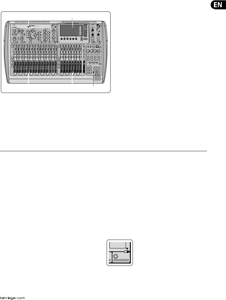
1.Operational Overview
(1) |
(3) |
(2) |
(4) |
(5) |
Mixer Operational Overview
This chapter will give you an overview of the basic operations of the mixer, allowing you to get up and running quickly. While reading through the information, we encourage you to experiment with the console’s different screens and controls. The console’s user interface was designed to be extremely to navigate through and learn. More specific details about various functions can be referenced later in the manual.
General user interface operation
The X32 user interface is divided into five major sections:
(1)Channel Strip
(2)Input Channels
(3)Display and Monitoring
(4)Group/Bus/Main Channels
(5)Scenes/Assign/Mute Groups
View buttons rule
Throughout the top panel of the console, you will find small buttons labeled View. Press these buttons to immediately switch the console’s large color display (known as the Main Display) to show information related to the section whose View button you have just pressed.
For example, if you are editing the equalizer and feel like seeing a large display of the EQ frequency response curve or corresponding EQ parameter value, simply press the adjacent View button in the EQ section. If you need to check where the talkback signal is being routed, simply press the View button next to the Talk button and the main display will show the details.
With the View button approach of the X32 console, there is almost never a need to drill down through multiple menu pages, since the View buttons will always take you directly to the relevant screen.
Tip: The Setup/Global tab on the main display allows preferences for the behavior of View and Select buttons to be adjusted.
Customizing the X32 through the Utilities page
Press the Utility button, located to the right of the main display, to bring up useful functions in a “context-sensitive” manner. For example:
• When you are adjusting the equalizer of a console channel,
pressing the Utility button will offer copying, pasting, loading or saving of equalizer settings
• Pressing the Utility button while editing a channel’s Preamp/Configuration screen will present a naming screen where you can customize the channel’s appearance on both the main display as well as the small channel display
• On the Routing pages, pressing the Utility button will offer loading or saving different presets of routing scenarios
• In the Scenes menu, pressing the Utility button offers copying, loading, saving or naming console scenes
Sometimes there is more to say
|
|
|
|
Some of the individual pages on the main display contain |
|
|
Dir 05 |
|
|
more adjustable parameters than can be controlled by |
|
|
Dir 06 |
|
|
||
|
|
|
|
the 6 rotary push encoders located beneath it. In these |
|
1 2 |
|||||
cases there is a small page number indication, e.g. “1/2”. |
|||||
|
Key |
||||
|
Source |
Simply press the Layer Up/Down buttons to switch |
|||
|
Select |
||||
|
|
|
|
between layers. |
|
6 X32 DIGITAL MIXER Preliminary User Manual
VIEW
VIEW
VIEW |
VIEW |
VIEW |
VIEW |
VIEW |
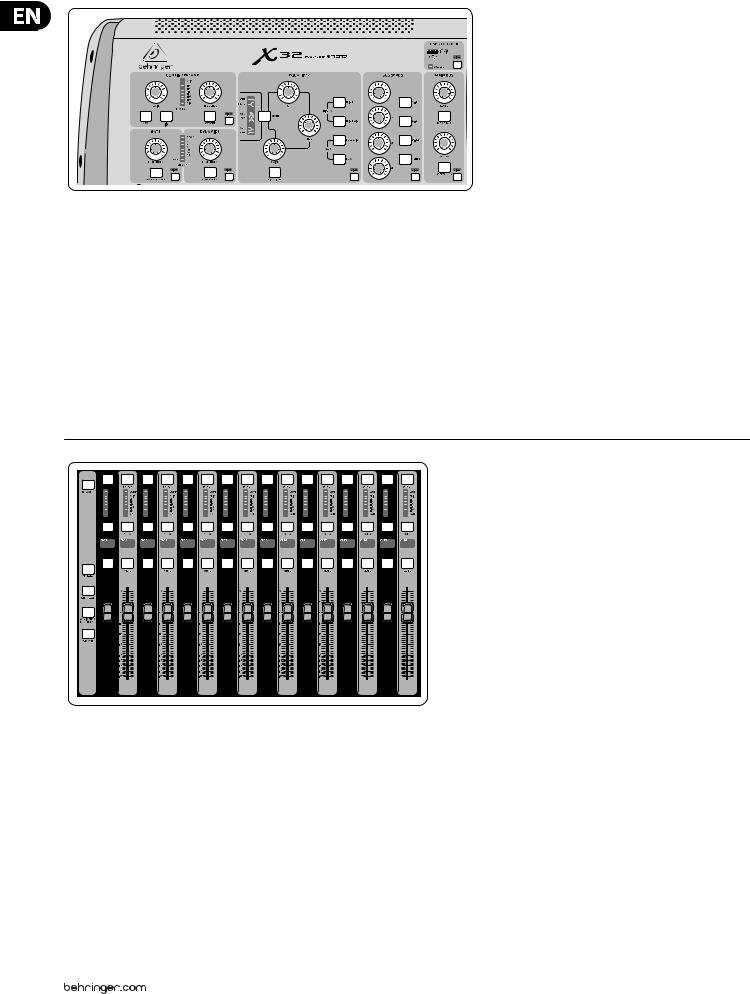
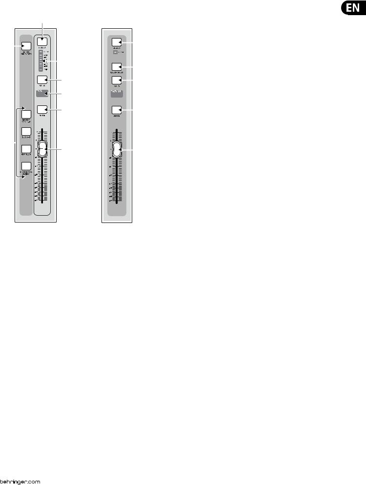
Channel Strip
The X32’s channel strip offers dedicated controls for the most important processing parameters of the currently selected channel. To adjust controls for a given channel strip, simply press the Select button on the desired input or output channel.
Certain sections of the channel strip (such as the low cut filter, noise gate, EQ and compressor) contain a respectively labeled button that can be pressed to switch the specific effect on and off. The button illuminates to show the effect is active, and goes dark when bypassed.
Within the channel strip, the rotary control knobs are surrounded by an amber LED collar that indicates the parameter’s value. Whenever this backlit knob is turned off, it indicates that this specific control/parameter is not available for the selected channel type. For example, if an output bus is currently selected,
the LED collar and the gain knob are turned off, because there is no input gain to be controlled on an output bus.
The channel strip consists of the following sub-sections:
• Config/Preamp
• Gate, Dynamics
• Equalizer
• Bus Sends, Main Bus
Each of these subsections correspond to the processing steps of the currently selected channel, and they each have their own View button that, when pressed, switches the Main Display to a page displaying all related parameters for
that subsection.
10 |
10 |
10 |
5 |
5 |
5 |
0 |
0 |
0 |
– 5 |
– 5 |
– 5 |
–10 |
–10 |
–10 |
–20 |
–20 |
–20 |
– 30 |
– 30 |
– 30 |
– 40 |
– 40 |
– 40 |
– 50 |
– 50 |
–50 |
– 60 |
– 60 |
– 60 |
– 00 |
– 00 |
– 00 |
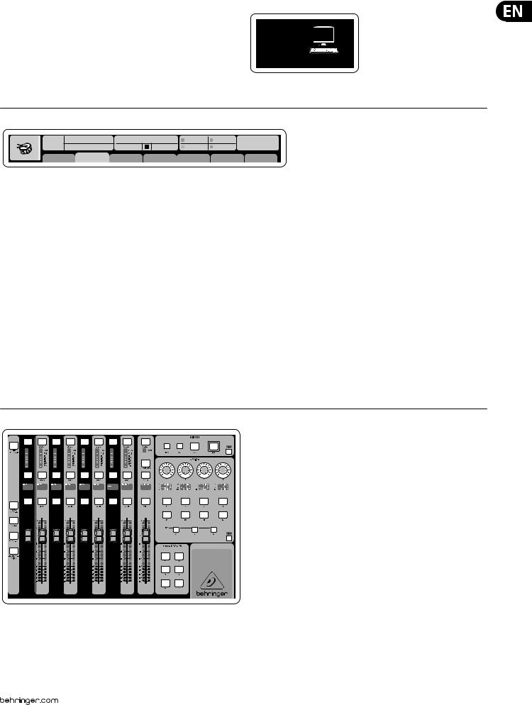
Input Channel Banks
You will find a select button on top of every channel that is used to direct the control focus of the user interface, including all channel related parameters (channel strip and main display), to that channel. Please note that at any time, there is exactly one channel selected (either Input Ch 1-32, Aux 1-8, FX Returns 1L-4R, Mix Bus 1-16, Main LR/C, or Matrix 1-6). DCA Groups (digitally controlled amplifier) cannot be selected because they control a number of assigned channels rather than one specific channel.
The Input Channels section of the console is located on the left hand side, and offers 16 separate input channel strips. These 16 channel strips represent three separate layers of inputs for the console, including:
• Input Channels 1-16
• Input Channels 17-32
• Auxiliary Inputs 1-6/USB playback/FX Returns 1L-4R
Press any of the correspondingly labeled layer buttons on the left side of the console to switch the input channel bank to any of the three layers listed above. The button will illuminate, reminding you which layer is active.
A fourth layer (Bus Masters) is also offered, allowing you to adjust the levels of the 16 Mix Bus Masters, which is useful when you wish to include Bus Masters into DCA Group assignments.
7 X32 DIGITAL MIXER Preliminary User Manual
On each fader strip you will find a motorized 100 mm level fader, Mute and Solo buttons, a Gate indicator, an input level meter, Compressor indicator, and the channel select button.
Each of the 16 input channels has an individual (and customizable) color LCD screen that can display a channel number, nickname, and even a graphical channel icon. In the event that a channel’s input source has been changed to an input signal that differs from the default setup, the LCD display will also indicate the name of the actual input source.
Ch01 PC
Aux5
Soundcard
Example: Channel 01 has the nickname Soundcard and is fed from Aux input 5.
Ch01 |
01 02: next |
0:00 |
- 0:00 |
B: - |
C: XUF |
15:33: 15 |
|
OpeningScene |
|
|
A: S16 |
A: 48K |
|
||
FatSnare |
home |
con g |
gate |
dyn |
eq |
sends |
main |
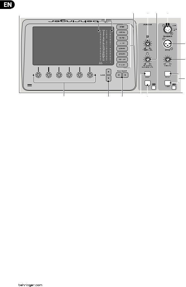
Main Display Area
The main color display presents information about various sections of the console. It can be switched to different screens using the console’s View buttons, as well as any of the 8 buttons on the right side of the display.
The top section of the main display permanently covers useful status information. The top left corner shows the selected channel number, its nickname and the selected icon. The next block shows the current scene number and name in amber, as well as the next upcoming scene. The center section displays the playback file name along with elapsed and remaining time and a recorder status icon. The next block to the right has 4 segments to show the status of AES50 ports A and B, the Card slot and the audio clock synchronization source and sample rate (top right). Small green square indicators show proper connectivity. The right most block shows the console time that can be set under Setup/Config.
When working with any given screen, press the Page keys located on the display bezel to switch to different screen pages.
Editing parameters or settings on each of the screens is done using the 6 associated push-encoders along the bottom edge of the display.
• Whenever there is a continuous control or list entry, you can turn the corresponding knob for editing, which is indicated by various circular icons
• When there is a switch or toggle function on one of these knobs, you will see a broad rectangular button along the lower edge of the field. Pressing the encoder changes the on/off state of the corresponding function. When the rectangular button in the display is dark grey, the corresponding function is off/inactive; when it is amber, the function is on/active
Monitoring and Talkback
There are two separate Level controls in this section, one for the headphone outputs located on either side of the console, and a second one for the monitor outputs located on the rear panel.
Press the section’s View button to edit various monitoring preferences, such as the input source for the phones bus and the monitor outputs.
This section also contains independent Talkback buttons (A and B). Press the View button to edit the Talkback preferences for the Talkback A path and Talkback B path separately. This screen also contains settings for the optional goose-neck lamp and the console’s internal test-tone generator.
VIEW
– 6
VIEW
Group/Bus Channel Banks
This section of the console offers eight channel strips, divided into the following layers:
• Eight DCA (digitally controlled amplifier) groups
• Mix Bus masters 1-8
• Mix Bus masters 9-16
• Matrix Outputs 1-6, and the main center bus
This section also contains a main LR output fader, which is independent and always available no matter which channel bank or layer is active.
When using the DCA Groups layer, the DCA Groups can be soloed and muted, but they cannot be selected. To edit the DCA group names, icons and colors, navigate to the Setup/DCA Groups page on the main display.
When using any of the output bus layers, note that the bottom LEDs on the meters in this section illuminate when the respective bus is fed from pre-fader sources of the selected channel.

8 X32 DIGITAL MIXER Preliminary User Manual
Various Assignments (DCA groups, mute groups, custom assignable controls)
• Assigning DCA Groups
Thanks to the two distinct fader groups (inputs on the left, outputs on the right), the task of assigning channels or buses to a virtual DCA Group is a breeze on the X32. Simply hold the respective DCA Group Select button on the right-hand side of the console, while pressing the select buttons for all the input channels that you wish to assign to said DCA Group. You can also press the DCA Group Select button in order to check which channels are already assigned to it. The assigned channel Select buttons will light up.
• Assigning Mute Groups
The mute group assignment process is similar to the above, but is designed with an additional precaution in order to prevent accidental muting of channels during a show. To assign input/output channels to one of the six mute groups (controlled by the buttons located to the right of the Main LR fader) you need to first switch on the Mute Grp button next to the main display. While holding the desired Mute Group button, select the desired input and output channels, which will now be assigned to the Mute Group. When you are done with assignment, switch off Mute Grp at the display, and the 6 Mute Group buttons will work as intended.
• Custom Assignable Controls:
The Assign section of the console offers three banks: A, B, and C. Each set of controls offers 4 rotary controls and 8 switches/buttons, allowing for freely customizable access to 36 random functions on the X32.
To make a custom assignment:
• Press the View button in the Assign section to edit the assignments
• Select the set of controls you wish to edit (A, B or C)
• Select the control 1-12 you wish to assign
• Select the parameter you wish to control and assign the function
Usually this is used to control a specific channel’s parameter, like the lead vocalist’s reverb send level.
The Jump-to-Page control is a special target type that does not alter any audio parameter, but rather brings you directly to any specified display page.
Buttons that had been used for Jump-to-Page previously can easily be reassigned to the current display view by holding the respective set button (A, B or C) depressed while pushing the desired assignable button. This method is more convenient than reassigning the jump function through the Assign menu.
The “Sends on Faders” Function
The X32 console features a very useful function that can be accessed by pressing the dedicated Sends on Faders button, located between the two fader sections.
The Sends on Faders function aids with level setting of channels sent to any of the 16 Mix Buses. It is only for channels assigned to Mix Buses 1-16, and does NOT work for DCA groups, main or matrix buses. The Sends on Faders function works in two convenient ways to cover the most obvious situations in a live sound environment :
When preparing a monitor mix for a specific musician
• Select the monitor bus (1-8, 9-16) that feeds the talent’s stage monitor
• Press the Sends on Faders button; it will illuminate
• Select one of the three input channel layers (CH 1-16, CH 17-32, Line-Aux/FX Ret)
• As long as the Sends on Faders is active, all faders in the input channels section (located on the left side of the console) correspond to the send levels to the selected (monitor) mix bus
When checking/editing where a selected input signal is (to be) sent to
• Select the input channel in the left section
• Press the Sends on Faders button; it will illuminate
• Select either bus channel layer 1-8 or 9-16
• The bus faders (located on right side of the console) now represent the send levels from the selected input channel (located on the left side of the console)
The option to use Sends on Faders in both ways, selecting an input or an output channel, is a special feature of the X32.
9 |
X32 DIGITAL MIXER Preliminary User Manual |
|
|
|
||||
|
Ch01 |
01 |
01: |
0:00 |
- 0:00 |
B: - |
C: XUF |
13:45 : 19 |
|
|
|
|
|
A: S16 |
A: 48K |
|
|
|
home analog out |
aux out p16 out card out |
aes50-a |
aes50-b |
||||
|
|
|
Channel Processing Block Patch |
|
|
|
Connected Devices |
|
|
Inputs 1-8 |
|
Inputs 9-16 |
Inputs 17-24 |
Inputs 25-32 |
Aux In 1-4 |
AES50 A |
|
|
Local In 1-8 |
|
Local In 1-8 |
Local In 1-8 |
Local In 1-8 |
Aux 1-4 |
|
|
|
Local In 9-16 |
|
Local In 9-16 |
Local In 9-16 |
Local In 9-16 |
Local 1-4 |
|
|
|
Local In 17-24 |
|
Local In 17-24 |
Local In 17-24 |
Local In 17-24 |
AES50 A1-4 |
|
|
|
Local In 25-32 |
|
Local In 25-32 |
Local In 25-32 |
Local In 25-32 |
AES50 B1-4 |
|
|
|
AES50 A1-8 |
|
AES50 A1-8 |
AES50 A1-8 |
AES50 A1-8 |
Card 1-4 |
|
|
|
AES50 A9-16 |
|
AES50 A9-16 |
AES50 A9-16 |
AES50 A9-16 |
|
|
|
|
AES50 A17-24 |
|
AES50 A17-24 |
AES50 A17-24 |
AES50 A17-24 |
|
|
AES50 B |
|
AES50 A25-32 |
|
AES50 A25-32 |
AES50 A25-32 |
AES50 A25-32 |
|
|
|
|
AES50 A33-40 |
|
AES50 A33-40 |
AES50 A33-40 |
AES50 A33-40 |
|
|
|
|
AES50 A41-48 |
|
AES50 A41-48 |
AES50 A41-48 |
AES50 A41-48 |
|
|
|
|
AES50 B1-8 |
|
AES50 B1-8 |
AES50 B1-8 |
AES50 B1-8 |
|
|
|
|
AES50 B9-16 |
|
AES50 B9-16 |
AES50 B9-16 |
AES50 B9-16 |
|
|
|
|
AES50 B17-24 |
|
AES50 B17-24 |
AES50 B17-24 |
AES50 B17-24 |
|
|
|
|
AES50 A25-32 |
|
AES50 A25-32 |
AES50 A25-32 |
AES50 A25-32 |
|
|
|
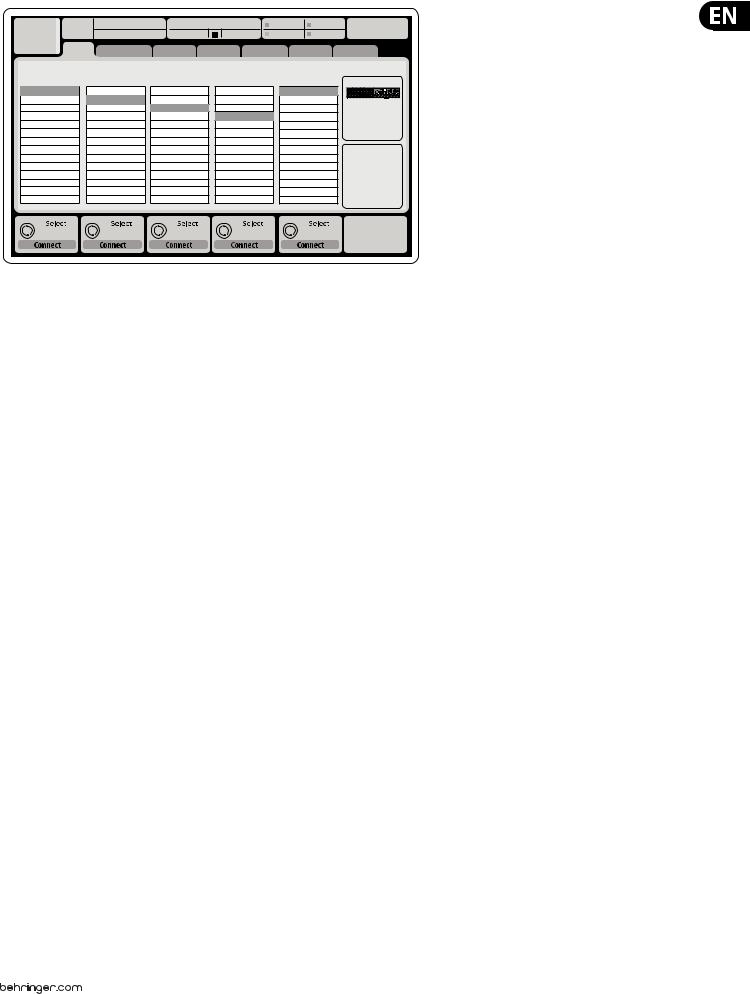
Routing I/O
The X32 console features 32 analog rear-panel XLR inputs with microphonepreamps, as well as 16 rear-panel XLR Outputs and 6 TRS Aux Sends and Returns. In addition, there are two AES50 ports, each featuring 48 input and output channels, and a card slot for 32 channels of input and output to and from a connected computer via USB 2.0 or IEEE1394.
Input Signals can be attached to the console’s internal audio processing engine in blocks of 8 signals from any one of the aforementioned input sources
Note: All signal blocks patched to the audio processing will be connected to the corresponding input channels automatically.
10 X32 DIGITAL MIXER Preliminary User Manual
|
Ch01 |
01 |
01: |
0:00 |
- 0:00 |
|
B: - |
|
C: XUF |
14:09 : 37 |
|||||||
|
|
|
|
|
|
|
|
|
|
|
|
A: S16 |
|
A: 48K |
|
|
|
|
|
|
analog out |
|
|
|
|
|
|
|
|
|
|
|
|
|
|
|
|
home |
aux out |
p16 out card out |
aes50-a |
aes50-b |
|||||||||||
|
|
Edit Output Assignment |
|
|
|
|
|
|
|
|
|
|
|
||||
|
Analog Output |
Current Setting |
|
Category |
|
|
|
Processed Output |
Signal Tap |
|
|
||||||
Output 01 |
MixBus |
OFF |
OFF |
Pre EQ |
0.3 |
ft |
Output 02 |
|
Main (LRC) |
Main L |
Post EQ |
0.10 |
m |
Output 03 |
|
Mix Bus |
Main R |
Pre Fader |
||
|
0.3 |
ms |
||||
Output 04 |
|
Matrix |
Main C/M |
Post Fader |
||
Output 05 |
|
Direct Out |
Main Bus 01 |
|
|
|
Output 06 |
|
Monitor |
Main Bus 02 |
|
|
|
Output 07 |
|
|
Main Bus 03 |
|
Delay |
|
Output 08 |
|
|
Main Bus 04 |
|
|
|
|
|
|
|
|
||
Output 09 |
|
|
Main Bus 05 |
|
|
|
Output 10 |
|
|
Main Bus 06 |
|
|
|
Output 11 |
|
|
Main Bus 07 |
|
|
|
Output 12 |
|
|
Main Bus 08 |
|
Delay |
|
Output 13 |
|
|
Main Bus 09 |
|
|
|
|
|
|
|
|
||
Output 14 |
|
|
|
|
|
|
Select |
Select |
Select |
Select |
Delay |
0.3 ms
Assign |
Set |
Delay |
Output Signals can be freely assigned from any internal signal to any of the following outputs:
• 16x analog local XLR outputs (with adjustable digital delay for time-alignment of speakers)
• 6x auxiliary sends on ¼" TRS outputs + 2x AES/EBU outputs
• 16x personal monitoring using the console’s P-16 Bus output connector
Any and all of the above signals can also be mirrored in blocks of 8 signals on either one of
• 48x channels on AES50 port A
• 48x channels on AES50 port B
• 32x channels on USB/Firewire interface card
Ch01 |
01 01: |
|
0:00 |
- 0:00 |
B: - |
C: XUF |
14:11 : 37 |
||
|
|
|
|
|
A: S16 |
A: 48K |
|
|
|
|
home |
con g |
gate |
dyn |
eq |
sends |
main |
||
|
|
|
|
|
|
Insert Position |
|
|
|
clip |
|
|
|
In |
t |
|
|
|
|
-6 |
48V |
|
|
|
|
|
|
||
-12 |
Reverse |
|
|
|
|
|
|
|
|
-18 |
|
|
|
|
|
|
|
||
|
|
|
|
Delay |
Pre |
Ins |
Post |
|
|
-24 |
|
|
|
|
|
||||
|
|
|
|
0.3 |
ft |
|
|
|
|
-30 |
Link |
Lo Cut |
|
Source |
|
Insert |
|
||
-36 |
|
0.10 |
m |
|
|
||||
|
OFF |
|
OFF |
|
|||||
-42 |
+0.0 dB |
2.0 |
Hz |
Input 01 |
0.03 |
ms |
|
InsFX 1L |
|
-48 |
|
|
|
Input 02 |
|
|
|
InsFX 1R |
|
-54 |
|
|
|
Input 03 |
|
|
|
InsFX 2L |
|
|
Gain |
Lo Cut |
|
Input 04 |
Delay |
|
|
InsFX 2R |
|
|
|
Input 05 |
|
|
InsFX 3L |
|
|||
|
|
|
|
Input 06 |
|
|
|
InsFX 3L |
|
Gain |
|
Lo Cut |
|
Source |
Delay |
Ins Pos |
|
Insert |
|
+0.00 dB |
20 |
Hz |
Input |
0.3 ms |
PRE |
|
InsF |
||
Link |
|
Lo Cut |
|
Select |
Delay |
|
Insert |
Connect |
|
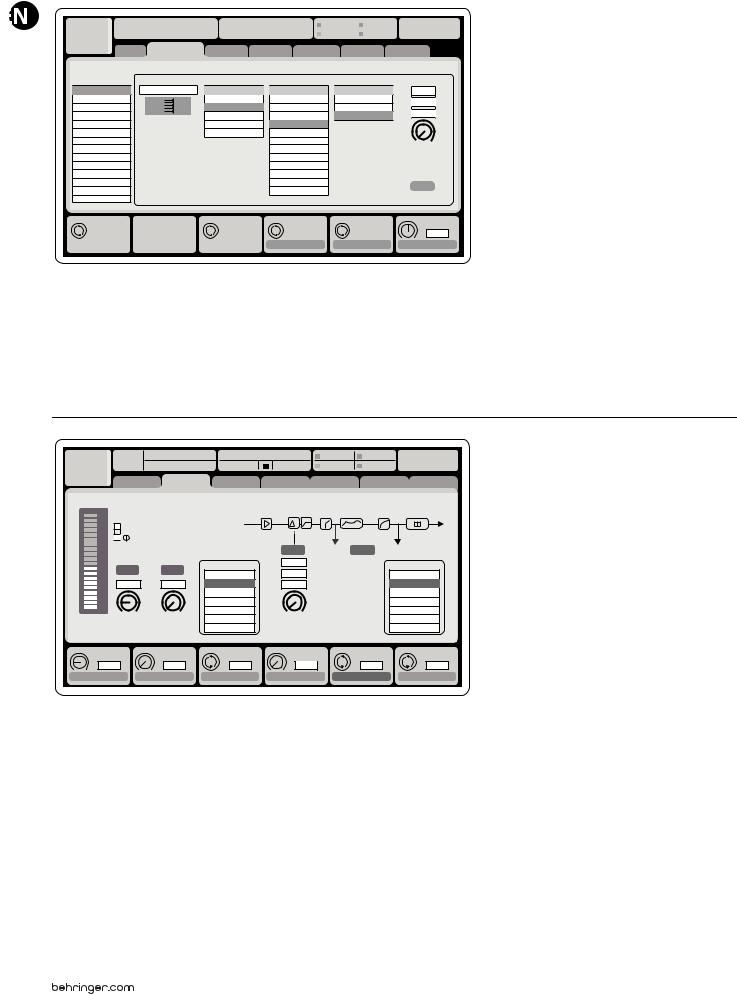
Input Channels 1-32 are pre-configured to use the first 32 input signals,
but can be patched to use any other available signal on the audio engine as well, including mix bus/sub group outputs. Changes of the Channel Source can be made on the Preamp Config page.
Aux Return Channels 1-8 are pre-configured to use the 6 aux input signals, and the two USB playback outputs, but can be patched to use any other available signal of the console as well.
FX Return Channels 1L-4R control the 4 stereo output signals of side-chain FX1-4.
11 |
|
X32 DIGITAL MIXER Preliminary User Manual |
|
|
|
|
|
|
|
|
|
|
|
|
|||||||||||||||
|
|
|
|
|
|
|
|
|
|
|
|
|
|
|
|
|
|
|
|
|
|
|
|
|
|
|
|
|
|
|
|
|
|
|
|
|
|
|
|
|
|
|
|
|
|
|
|
|
|
|
|
|
|
|
|
|
|
|
|
|
|
|
|
|
|
LeOnde.mp3 |
|
|
|
|
13:44:43 |
|
|
|
|
|
|
|
MyProj.prj |
|
|
|
|||||||
|
|
|
|
|
|
00.05.00 |
|
|
00.00.00 |
|
29 November 2010 |
|
|
|
|
|
|
Scene01 |
|
|
|
||||||||
|
|
|
|
|
|
home |
|
con g |
|
gate |
dyn |
eq |
|
sends |
|
main |
|
|
|||||||||||
|
|
|
|
|
|
|
|
|
|
|
|
|
|
|
|
|
|
|
|
|
|
|
|
|
|
|
|
|
|
|
|
|
|
clip |
|
Bus Con guration |
|
|
|
Bus Insert Position |
|
|
|
|
|
|
|
||||||||||||
|
|
|
|
|
|
|
|
|
|
|
Channel Sends |
∑ |
|
|
|
|
|
|
|
|
|
|
|
||||||
|
|
|
|
-6 |
|
|
|
|
|
|
|
|
|
|
|
|
|
|
|
|
|
|
|||||||
|
|
|
|
-12 |
|
|
|
|
|
|
|
|
|
|
|
|
|
|
|
|
|
|
|
|
|
|
|
|
|
|
|
|
|
-18 |
|
|
|
|
|
|
|
|
|
|
|
|
|
|
|
|
|
|
|
|
|
|
|
|
|
|
|
|
|
Link |
|
|
|
All Channel Sends |
|
|
Pre |
Insert |
Post |
|
|
|
|||||||||||||
|
|
|
|
-24 |
|
|
|
|
|
|
|
|
|||||||||||||||||
|
|
|
|
-30 |
|
|
|
|
|
|
|
|
|
|
|
|
Insert |
|
|
|
|||||||||
|
|
|
|
-36 |
|
|
|
|
|
|
|
|
|
|
|
|
|
|
|
||||||||||
|
|
|
|
|
|
|
|
|
|
|
|
|
|
|
|
|
|
|
|||||||||||
|
|
|
|
-42 |
|
|
|
|
|
Pre Con guration |
|
|
|
|
|
|
|
Ins 01 |
|
|
|
|
|||||||
|
|
|
|
-48 |
|
|
|
|
|
... |
|
|
|
|
|
|
|
|
|
|
Ins 02 |
|
|
|
|
||||
|
|
|
|
|
|
|
|
|
|
|
|
|
|
|
|
|
|
|
|
|
|
||||||||
|
|
|
|
-54 |
|
|
|
|
|
Inputs |
|
|
|
|
|
|
|
|
Ins 03 |
|
|
|
|
||||||
|
|
|
|
|
|
|
|
|
Pre EQ |
|
|
|
|
|
|
|
|
Ins 04 |
|
|
|
|
|||||||
|
|
|
|
|
|
|
|
|
|
|
|
|
|
|
|
|
|
|
|||||||||||
|
|
|
|
|
|
|
|
|
|
|
Pre Fader |
|
|
|
|
|
|
|
|
... |
|
|
|
|
|
|
|||
|
|
|
|
|
|
|
|
|
|
|
Post Fader |
|
|
|
|
|
|
|
|
FX 01 |
|
|
|
|
|||||
|
|
|
|
|
|
|
|
|
|
|
Sub Grou |
|
|
|
|
|
|
|
|
FX 02 |
|
|
|
|
|||||
|
|
|
|
|
|
|
|
|
|
|
|
|
|
|
|
|
|
|
|
|
|
|
|
|
|
|
|
|
|
|
|
|
|
Gain |
dB |
|
|
|
|
Send Pos. |
|
|
|
|
Insert Pos. |
|
Insert |
|
|
||||||||||
|
|
|
|
|
00.00 |
|
|
|
|
|
Inputs |
|
|
|
|
|
|
|
Pre |
|
|
|
|
|
|
|
|
||
|
|
|
Link |
|
|
|
|
|
Bus Sends |
|
|
|
|
Insert |
Connect |
|
|
||||||||||||
|
|
|
|
|
|
|
|
|
|
|
|
|
|
|
|
|
|
|
|
|
|
|
|
|
|
|
|
|
|
The configuration of Mix Bus Channels 1-16 can be pre-set (in the Setup/Global page) or can also be configured on an individual, per-channel basis. The bus processing includes (in this order):
• Insert point (swappable between post-EQ and pre-EQ operation)
• 6-band fully parametric EQ
• Compressor/expander (swappable between post-EQ and pre-EQ operation)
• Bus sends to 6 matrices (post-fader)
• Main LR panning
• Mono/Center level
Main Bus Channels LR/C are always available and independent from Mix Buses. The processing steps for this signal path include (in this order):
• Insert point (swappable between post-EQ and pre-EQ operation)
• 6-band fully parametric EQ
• Compressor/expander (swappable between post-EQ and pre-EQ operation)
• Bus sends to 6 matrices (post-fader)
Matrix Channels 1-6 are fed exclusively by MAIN LRC and Mix Bus 1-16 signals. The processing steps include (in this order):
• Insert point (swappable between post-EQ and pre-EQ operation)
• 6-band fully parametric EQ
• Compressor/expander (swappable between post-EQ and pre-EQ operation)
Effects Processing 1-8
The X32 console contains eight true-stereo internal effects engines.
• FX 1-4 can be configured as side chain or insert effects, while FX 5-8 can only be used in insert points of channels or buses
• The returns of side chain FX 1-4 can always be controlled using the 3rd bank (layer) of the input channels - Aux/USB/FX Returns. Note that the return signals of FX 1-4 have separate faders for left and right
• The FX Home screen allows selection of the FX 1-4 input sources and selecting the effects type/algorithm for each of the 8 FX slots of the virtual rack
• The subsequent tabs FX 1-FX 8 of the FX screen allow editing all parameters of the chosen effects processor
12X32 DIGITAL MIXER Preliminary User Manual
2.Callouts
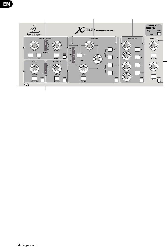
2.1 Channel Strip
(1) |
(3) |
(4) |
VIEW (5)
(5)
VIEW
(6)
VIEW |
VIEW |
(2)
(1)PREAMP – Adjust the preamp gain for the selected channel with the Gain knob. Press the 48 V button to apply phantom power for use with condenser microphones and press the  button to reverse the channel’s phase. The meter displays the selected channel’s level. Press the Low Cut button and select the desired high-pass frequency to remove unwanted lows. Press the View button to access more detailed parameters on the Main Display.
(2)GATE/DYNAMICS – Press the Gate/Ducker button to engage the noise gate and adjust the threshold accordingly. Press the Comp/Exp button to engage the compressor and adjust the threshold accordingly. When the signal level in the meter drops below the selected Gate threshold, the noise gate will silence the channel. When the signal level reaches the selected Dynamics threshold, the peaks will be compressed. Press the View buttons to access more parameters on the Main Display.
(3)EQUALIZER – Press the Equalizer button to engage this section. Select one of the 4 frequency bands with the High, High Mid, Low Mid, and Low knobs. Press the Mode button to cycle through the types of EQ
available. Select the specific frequency to be adjusted with the Freq knob, and adjust the bandwidth of the EQ with the Q knob. Finally, boost or cut the selected frequency with the Gain knob. Press the View button for more editing options.
(4)BUS SENDS – Quickly adjust the bus sends by selecting one of the 4 banks, followed by one of the 4 knobs. Press the View button for more detailed editing and routing.
(5)USB RECORDER – Connect a thumb drive to install firmware updates and to record performances. See the Topic Guide section for details.
(6)MAIN BUS – Press the Mono Bus or Stereo Bus to assign the channel to the main mono or stereo bus. When Stereo Bus is selected, the Pan/Bal adjusts the left-to-right positioning. Adjust the overall send level to the Mono Bus with the Level knob. Press the View button for more editing options.
13X32 DIGITAL MIXER Preliminary User Manual
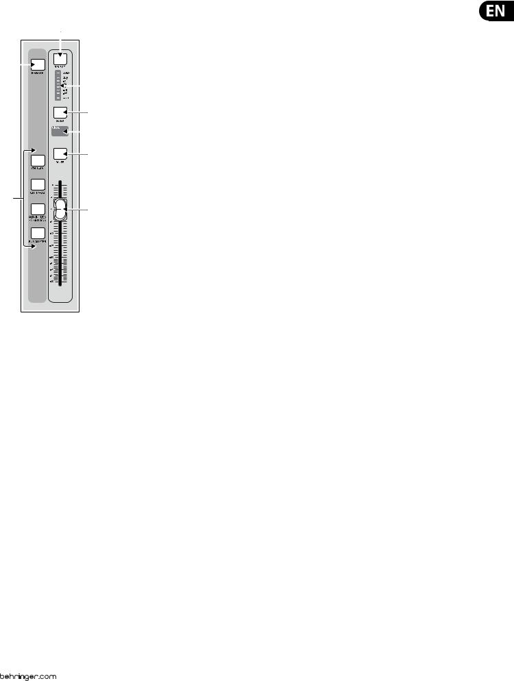
2.2Input Channel Banks
(9)
(8)
(10)
(11)
(12)
(13)
(7)
(14)
(7)LAYER SELECT – Select either the channels 1-16, channels 17-32, Aux In/USB/FX Returns, or Bus Masters layer with these 4 buttons. The currently active layer will light.
(8)DAW REMOTE – Press this to enable DAW remote control.
(9)SELECT – Press this button to select an input or bus (depending which layer is active) and allow it to be edited by the Channel Strip and Main Display.
(10)CHANNEL METER – This displays the signal level of the input or bus (depending which layer is active). The Gate and Comp LEDs light to indicate that noise gate and/or compression are active.
(11)SOLO – Press this button to send the channel to the Solo Bus.
(12)MINI DISPLAY – Information such as channel number, nickname, input source and graphical icon are displayed on this color LCD screen.
(13)MUTE – Press this button to mute the channel.
(14)FADER – Use this to adjust the channel volume or bus send in ’Sends on Faders’ mode. The faders will automatically display the current status as layers and functions are changed.
14X32 DIGITAL MIXER Preliminary User Manual
2.3Display and Monitoring
(18) |
(19) |
(20) |
(21) |
(24) |
|||
|
|
|
|
|
|
|
|
|
|
|
|
|
|
|
|
|
|
|
|
|
|
|
|
(25)
(26)
(27)
VIEW
(15) |
(16) |
(17) |
(22) |
|
|
(23) |
|||||
(15)PUSH ENCODERS – These 6 controls adjust the parameters presented at the bottom of the Main Display. The editable function will show a circular icon in the display when continuous control is available. The function will show a broad rectangular icon to indicate that a switch or toggle can be accessed by pushing the encoder.
(16)LAYER BUTTONS – Some screens in the Main Display have more than 6 editable parameters which can be accessed by pressing the Layer Up or Down buttons.
(17)PAGE SELECT BUTTONS – Use these to scroll through the available screens or to confirm/decline certain actions.
(18)MAIN/SOLO METERS – The main stereo output level is displayed here along with the solo level of all channels whose Solo button is active.
(19)CATEGORY SELECT BUTTONS – Press one of these buttons to jump directly to the subject you wish to edit or configure.
(20)MONITOR LEVEL – Adjust the level of the Monitor outputs with this knob.
(21)PHONES LEVEL – Adjust the volume of the headphone outputs, located inside the left and right side caps.
(22)MONITOR MONO – Press this button to monitor the audio in mono.
(23)DIM – Press this button to reduce the monitor volume. Press the View button to adjust the amount of attenuation along with all other monitoring-related functions.
(24)LAMP INPUT – Connect a standard 12 V, 5 Watt gooseneck lamp here.
(25)TALKBACK INPUT – Connect a talkback mic via standard XLR cable to this input.
(26)TALK LEVEL – Adjust the level of the talkback mic with this knob.
(27)TALK A/B – Select the destination for the talkback mic signal with these buttons. Press the View button to edit the talkback routing for A and B.
15X32 DIGITAL MIXER Preliminary User Manual
2.4Group/Bus Banks
(30)
(29)
(31)
(32)
(33)
(34)
(28)
(35)
(28)GROUP/BUS LAYERS – Select between DCA groups 1-8, Buses 1-8 or 9-16, or Matrices 1-6 and the main center bus with these buttons. The currently active layer will light.
(29)SENDS ON FADERS – Press this button to activate the Sends on Faders
(36) |
function. See the Topic Guide for more details. |
|
(30)SELECT – Press this button to select a DCA or bus (depending which layer is active) and allow it to be edited by the Channel Strip and Main Display.
(37) |
(31) |
GROUP/BUS METER – This displays the signal level of the DCA or bus |
(38) |
|
(depending which layer is active). The Pre LED indicates that the bus is |
|
sourced pre-fader, while the Comp LED indicates that compression is active. |
|
|
|
|
|
(32) |
SOLO – Press this button to solo the DCA or bus. |
(39) |
(33) |
MINI DISPLAY – Information such as matrix/bus number, |
|
nickname, input source and graphical icon are displayed on this color |
|
|
|
LCD screen.
(34)MUTE – Press this button to mute the DCA or bus.
(35)FADER – Use this to adjust the bus level. The faders will automatically
(40) |
display the current status as layers and functions are changed. |
(36)MAIN SELECT – Press this button to select the main bus for editing.
(37)CLEAR SOLO – Press this button to release all sources assigned to the solo bus.
(38)MAIN SOLO – Press this button to solo the main bus.
(39)MAIN MUTE – Press this button to mute the main bus.
(40)MAIN FADER – This fader adjusts the output of the main bus.
16X32 DIGITAL MIXER Preliminary User Manual
2.5Scenes, Assign, Mute Groups
(46)
VIEW
(45)


(44)
(43) |
|
(42) |
VIEW |
(41)
(41)MUTE GROUPS – Press one of these buttons to activate one of the mute groups. See the Topic Guide for details.
(42)SET SELECT BUTTONS – Press one of these buttons to activate one of the 3 layers of custom assignable controls.
(43)CUSTOM ASSIGN BUTTONS – Assign these 8 buttons to various parameters for instant access to commonly used functions. See the Topic Guide for details.
(44)ASSIGN DISPLAYS – These displays provide quick reference to the assignments of the active layer of custom controls.
(45)CUSTOM ASSIGN KNOBS – Assign these 4 knobs to various parameters for instant access to commonly used functions. See the Topic Guide for details.
(46)SCENES BUTTONS – Use these buttons select and activate saved scenes. See the Topic Guide for details.
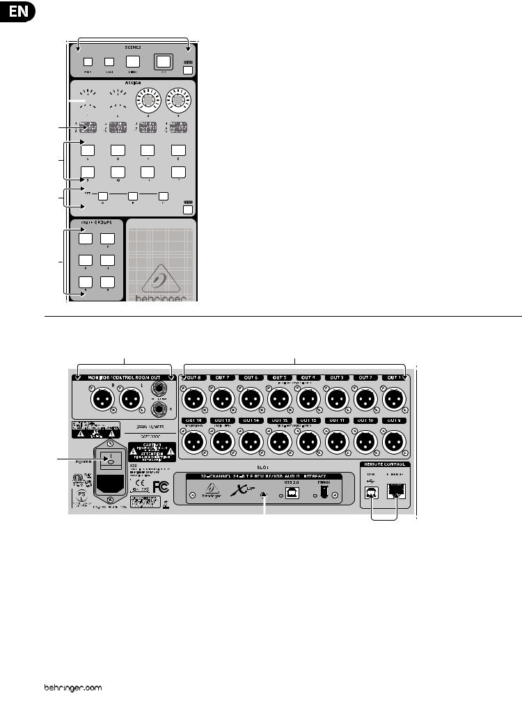
2.6 Rear Panel Connections
(47) |
(48) |
(49)
|
|
|
|
|
|
|
|
|
|
|
|
|
|
|
|
|
|
|
|
|
|
|
|
|
|
|
|
|
|
|
|
|
|
|
|
|
|
|
|
|
|
|
|
|
|
|
|
|
|
|
|
|
|
|
|
|
|
|
|
|
|
|
|
|
|
|
|
|
|
|
|
|
|
|
|
|
|
|
|
|
|
|
|
|
|
|
|
|
|
|
|
|
|
|
|
|
|
|
|
|
|
|
|
|
|
|
|
|
|
|
|
|
|
|
|
|
|
|
|
|
|
|
|
|
|
(50) |
(51) |
||||||||||||||||
(47)MONITOR / CONTROL ROOM OUTPUTS – Connect a pair of studio monitors using XLR or 1" cables.
(48)OUTPUTS 1-16 – Send audio to external equipment using XLR cables. Outputs 15 and 16, by default, carry the main stereo bus signals.
(49)POWER SWITCH – Turn the power on and off with this switch.
(50)XUF USB/FW CARD – Transmit up to 32 channels of audio to and from a computer via USB 2.0 or FireWire 400 cables.
(51)REMOTE CONTROL – Connect to a PC for remote control via USB or Ethernet cable.
17 X32 DIGITAL MIXER Preliminary User Manual
(52) |
(53) |
(54) |
(55) |
|
|
||||
|
|
|
|
|
|
|
|
|
|
|
|
|
|
|
|
|
|
|
|
|
|
|
|
|
|
|
|
|
|
|
|
|
|
|
|
|
|
|
|
|
|
|
|
|
|
|
|
|
|
|
|
|
|
|
|
|
|
|
|
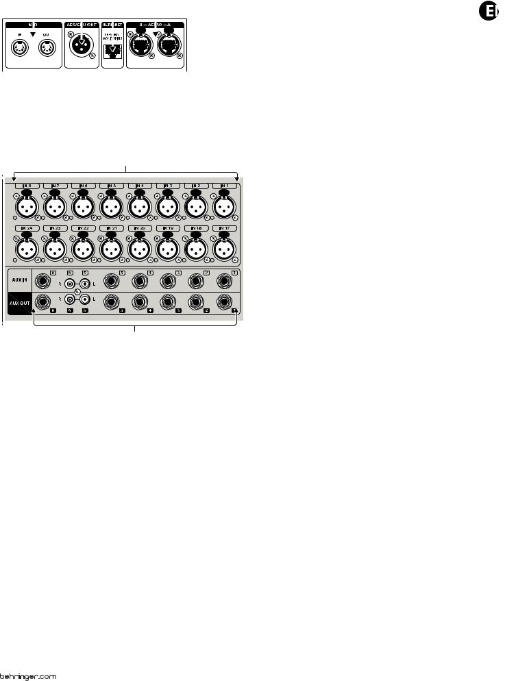
(52)MIDI IN/OUT – Send and receive MIDI commands via 5-pin DIN cables.
(53)AES/EBU OUT – Send digital audio via 3-pin AES/EBU XLR cable.
(54)ULTRANET – Connect to a BEHRINGER P-16 personal monitoring system via Ethernet cable.
(55)AES50 A/B – Transmit up to 96 channels in and out via Ethernet cables.
(56)
(57)
(56)INPUTS 1-32 – Connect audio sources via XLR cables.
(57)AUX IN/OUT – Connect to and from external equipment via 1" or RCA cables.
18 X32 DIGITAL MIXER Preliminary User Manual
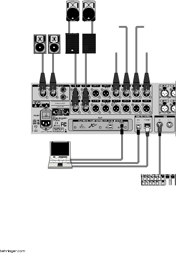
 3. Hook-Up Diagrams
B215D
F1320D
B3031A |
B1800D-PRO |
|
Laptop
FCB1010 MIDI Pedal

19 X32 DIGITAL MIXER Preliminary User Manual
GTX30 |
DI Box |
Keyboard |
|
XM8500
HPX6000
(Sidecap output)
P-16 D
2-TRACK HARD DISK RECORDER
S16 Digital Snake
iPod
P-16 M |
FX2000 |
20X32 DIGITAL MIXER Preliminary User Manual
4.FX Descriptions
FX Descriptions
Here is a list and brief description of the effects available on the X32.
When Stereo and Dual versions of an effect are offered, use the Stereo version when the left and right signal are to be altered together (e.g. on linked stereo channels or buses), or Dual when you want to dial different settings for the left and right signal. See the Topic Guide for instructions on how to add effects to a channel or bus.
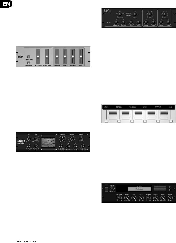
Stereo Precision Limiter
Stereo Precision Limiter allows you to set a precise volume limit,
ensuring distortion-free, optimal signal integrity. Use X32’s Stereo Precision Limiter to boost quiet signals or preventing clipping while preserving the level of “hot” signals.
AUTOGAIN activates an additional long-term gain correction, allowing automatic gain scaling of varying input level ranges. STEREO LINK applies limiting to both channels equally when activated. INPUT GAIN provides up to 18 dB of gain to the input signal prior to limiting. OUTPUT GAIN sets the final gain level of the processed signal. SQUEEZE adds compression to the signal to add punch and a slight distortion depending on the amount you dial in. ATTACK sets the attack time, ranging from 0.05 mS to 1 mS. RELEASE adjusts the release time from
0.05 mS to 1.04 seconds. KNEE adjusts the soft limiting threshold point from hard limiting (0 dB) to maximum soft limiting (10 dB).
Triple Delay
Sometimes called a 3-Tap Delay, the Triple Delay provides three delay stages with independent frequency, gain, and pan controls. Create time-based echo effects with the Triple Delay to increase the sense of stereo separation.
TIME BASE sets the master delay time, which is also the delay time for the first stage. GAIN BASE sets the gain level of the first stage of the delay. PAN BASE sets the position of the first delay stage in the stereo field. LO CUT sets the frequency at which the source signal can begin passing through the delay. HI CUT sets the frequency at which the source signal no longer passes through the delay. X-FEED indicates that stereo cross-feedback of the delays is active. MONO activates
a mono mix of both channels for the delay input. FEED adjusts the amount of feedback. FACTOR A controls the amount of delay time in the second stage of the delay. GAIN A controls the gain level of the second delay stage. PAN A sets the position of the second delay stage in the stereo field. FACTOR B controls the amount of delay time in the third stage of the delay. GAIN B controls the gain
level of the third delay stage. PAN B sets the position of the third gain stage in the stereo field.
Ambience
Stereo Delay
Stereo Delay provides independent control of left and right delay (echo) times and features high and low pass filters for enhanced tone shaping of the
delayed signals. Use the Stereo Delay to give your mono signals a wide presence in the stereo field.
The MIX control lets you blend the source signal and the delayed signal.
TIME adjusts the master delay time up to three seconds. LO CUT adjusts the low frequency cut, allowing lower frequencies to remain unaffected by the delay. HI CUT adjusts the high frequency cut, allowing higher frequencies to remain unaffected by the delay. FACTOR L sets the delay on the left channel to rhythmic fractions of the master delay time. FACTOR R sets the delay on the right channel
to rhythmic fractions of the master delay time. OFFSET LR adds a delay difference between the left and right delayed signals. The FEED LO CUT/HI CUT adjusts filters in the feedback paths. FEED L and FEED R control the amount of feedback for
the left and right channels. MODE sets the feedback mode: Mode ST sets normal feedback for both channels, X crosses feedbacks between left and right channels. M creates a mono mix within the feedback chain.
Ambience creates a customizable virtual acoustic space in which to place the elements of a mix. Use Ambience to add warmth and depth without coloring the direct sound. (Inspired by the Lexicon Ambience Algorithm)
PRE DELAY sets the time before the reverb follows the source signal. DECAY adjusts the time it takes for the reverb to completely dissipate.
SIZE controls the room size emulation. DAMPING controls the high frequency decay within the reverb tail. DIFFUSE controls the initial echo density. Level sets the volume output of the affected signal. LO CUT adjusts the low frequency cut, allowing lower frequencies to remain unaffected by the reverb. HI CUT adjusts the high frequency cut, allowing higher frequencies to remain unaffected by the reverb. MOD adjusts the level of reverb decay modulation. TAIL GAIN adjusts the volume of the reverb tail.
Reverse Reverb
Reverse Reverb takes the trail of a reverb, turns it around, and places it in front of the sound source. Use the swelling crescendo of the Reverse Reverb to add an ethereal quality to vocal and snare tracks. (Inspired by the Lexicon 300/480L)
Adjusting the PRE DELAY knob adds up to 200 milliseconds of time before the reverb follows the source signal. The DECAY knob adjusts the time it takes for the reverb to completely dissipate. RISE controls how quickly the effect builds
21 X32 DIGITAL MIXER Preliminary User Manual |
|
|
up. DIFF(USION) controls the initial reflection density. SPREAD controls how the |
Hall Reverb |
|
|
||
reflection is distributed through the envelope of the reverb. The LO CUT knob |
|
|
|
|
|
sets a low frequency beneath which the source signal will not pass through the |
|
|
reverb. The HiSvFr/HiSvGn knobs adjust a Hi-Shelving filter at the input of the |
|
|
reverb effect. |
|
|
Gated Reverb |
|
|
This effect was originally achieved by combining a reverb with a noise gate.
Our gated reverb creates the same impression by a special shaping of the reverb tail.
Gated Reverb is especially effective for creating a 1980s-style snare sound or to enlarge the presence of a kick drum. (Inspired by the Lexicon 300/480L)
PRE DELAY controls the amount of time before the reverberation is heard following the source signal. DECAY controls the amount of time it takes for the reverb to dissipate. ATTACK controls how fast the reflection density builds up. DENSITY shapes the reverb decay tail. The higher the density, the greater the number of sound reflections. SPREAD controls how the reflection is distributed through the envelope of the reverb. The LO CUT knob sets the frequency beneath which the source signal will not pass through the reverb. The HiSvFr/ HiSvGn knobs adjust a Hi-Shelving filter at the input of the reverb effect. DIFF(USION) controls the initial reflection density.
Plate Reverb
A plate reverb was originally created by sending a signal through a transducer to create vibrations on a plate of sheet metal which were then picked up as an audio signal. Our algorithm simulates that sound with high initial diffusion and a bright colored sound. X32’s Plate Reverb will give your tracks the sound heard on countless hit records since the late 1950s. (Inspired by the Lexicon PCM-70)
PRE DELAY controls the amount of time before the reverberation is heard following the source signal. DECAY controls the amount of time it takes for the reverb to dissipate. SIZE adjusts the size of the virtual room created by the reverb effect. The DAMP knob adjusts the decay of high frequencies within the reverb tail. DIFF(USION) controls the initial reflection density. The LO CUT knob sets the frequency beneath which the source signal will not pass through the reverb. The HI CUT knob sets the frequency above which the source signal will not pass through the reverb. The BASS MULT(IPLIER) knob adjusts the decay time of the bass frequencies. XOVER controls the crossover point for bass. MOD DEPTH and SPEED control the intensity and speed of the reverb tail modulation.
Classic Hall Reverb simulates the reverberation that occurs when sound is recorded in medium to large-sized concert halls. Use the Hall Reverb to give your mix a lush, three-dimensional quality that will make your performance sound larger than life. (Inspired by the Lexicon Hall)
The PRE DELAY slider controls the amount of time before the reverberation is heard following the source signal. DECAY controls the amount of time it takes for the reverb to dissipate. SIZE controls the perceived size of the space being created by the reverb effect. The DAMP slider adjusts the decay of high frequencies within the reverb tail. DIFF(usion) controls the initial reflection density. SHAPE adjusts the contour of the reverberation envelope.
Vintage Room
Vintage Room simulates the reverberation that occurs when sound is recorded in a small room. When you want to add a bit of warmth and just a touch of reverb, X32’s Vintage Room breathes life into close-miced guitar and drum tracks. (Inspired by the Quantec QRS)
The VU meter displays the input and output levels. Set the early reflection times for the left and right channel with ER DELAY L and ER DELAY R. ER LEVEL sets the loudness of the early reflection level. REV DELAY controls the amount of time before
the reverberation is heard following the source signal. HI/LOW MULTIPLY adjusts the decay time of the high and bass frequencies. TIME shows the duration of the reverb effect. ROOM SIZE adjusts the size of the room effect being created incrementally from small to large. HIGH CUT sets the frequency above which the source signal does not pass through the reverb. DENSITY manipulates the reflection density in the simulated room. (This slightly changes the reverb decay time). LOW CUT sets the frequency below which the source signal does not pass through the reverb.
Vintage Reverb
Based on the legendary EMT250, X32’s Vintage Reverb delivers shimmering bright reverb that won’t drown out or overpower your live or recorded tracks. Use Vintage Reverb to sweeten vocals and snare drums without sacrificing clarity.
When layer 1 is selected, the first slider on the left sets the reverb time from 4 milliseconds to 4.5 seconds. Slider 2 controls the low frequency multiplier
decay time. Slider 3 controls the high frequency multiplier decay time. Slider 4 controls the amount of modulation in the reverb tail. When layer two is selected, slider 1 adjusts the pre delay. Slider 2 selects the low cut frequency. Slider 3 selects the Hi Cut frequency. Slider 4 adjusts the output level of the reverb.
Loading...