


DENOISER® SNR2000
User’s Manual
Version 2.3 June 2002
www.behringer.com
ENGLISH

DENOISER SNR2000
SAFETY INSTRUCTIONS
CAUTION: To reduce the risk of electrical shock, do not remove the cover (or back). No user serviceable parts inside; refer servicing to qualified personnel.
WARNING: To reduce the risk of fire or electrical shock, do not expose this appliance to rain or moisture.
This symbol, wherever it appears, alerts you to the presence of uninsulated dangerous voltage inside the enclosure
– voltage that may be sufficient to constitute a risk of shock.
This symbol, wherever it appears, alerts you to important operating and maintenance instructions in the accompanying literature. Read the manual.
DETAILED SAFETY INSTRUCTIONS:
All the safety and operation instructions should be read before the appliance is operated.
Retain Instructions:
The safety and operating instructions should be retained for future reference.
Heed Warnings:
All warnings on the appliance and in the operating instructions should be adhered to.
Follow instructions:
All operation and user instructions should be followed.
Water and Moisture:
The appliance should not be used near water (e.g. near a bathtub, washbowl, kitchen sink, laundry tub, in a wet basement, or near a swimming pool etc.).
Ventilation:
The appliance should be situated so that its location or position does not interfere with its proper ventilaton. For example, the appliance should not be situated on a bed, sofa rug, or similar surface that may block the ventilation openings: or placed in a built-in installation, such as a bookcase or cabinet that may impede the flow of air through the ventilation openings.
Heat:
The appliance should be situated away from heat sources such as radiators, heat registers, stoves, or other appliances (including amplifiers) that produce heat.
Power Source:
The appliance should be connected to a power supply only of the type described in the operating instructions or as marked on the appliance.
Grounding or Polarization:
Precautions should be taken so that the grounding or polarization means of an appliance is not defeated.
Power-Cord Protection:
Power supply cords should be routed so that they are not likely to be walked on or pinched by items placed upon or against them, paying particular attention to cords and plugs, convenience receptacles and the point where they exit from the appliance.
Cleaning:
The appliance should be cleaned only as recommended by the manufacturer.
Non-use Periods:
The power cord of the appliance should be unplugged from the outlet when left unused for a long period of time.
Object and Liquid Entry:
Care should be taken so that objects do not fall and liquids are not spilled into the enclosure through openings.
Damage Requiring Service:
The appliance should be serviced by qualified service personnel when:
-the power supply cord or the plug has been damaged; or
-objects have fallen, or liquid has been spilled into the appliance; or
-the appliance has been exposed to rain; or
-the appliance does not appear to operate normally or exhibits a marked change in performance; or
-the appliance has been dropped, or the enclosure damaged.
Servicing:
The user should not attempt to service the appliance beyond that which is described in the Operating Instructions. All other servicing should be referred to qualified service personnel.
2

DENOISER SNR2000
FOREWORD
Dear Customer,
Welcome to the team of DENOISER users and thank you very much for expressing your confidence in BEHRINGER products by purchasing the SNR2000.
It is one of my most pleasant tasks to write this letter to you, because it is the culmination of many months of hard work delivered by our engineering team to reach a very ambitious goal: making an outstanding device that will become a standard tool used by studios and P.A. companies. The task to design the DENOISER certainly meant a great deal of responsibility, which we assumed by focusing on you, the discerning user and musician. It also meant a lot of work and night shifts to accomplish this goal. But it was fun, too. Developing a product usually brings a lot of people together, and what a great feeling it is when everybody who participated in such a project can be proud of what we’ve achieved.
It is our philosophy to share our joy with you, because you are the most important member of the BEHRINGER family. With your highly competent suggestions for new products you’ve greatly contributed to shaping our company and making it successful. In return, we guarantee you uncompromising quality (manufactured under ISO9000 certified management system) as well as excellent technical and audio properties at an extremely affordable price. All of this will enable you to fully unfold your creativity without being hampered by budget constraints.
We are often asked how we are able to produce such high-grade devices at such unbelievably low prices. The answer is quite simple: it’s you, our customers! Many satisfied customers mean large sales volumes enabling us to get better conditions of purchase for components, etc. Isn’t it only fair to pass this benefit back to you? Because we know that your success is our success too!
I would like to thank all people whose help on “Project DENOISER” has made it all possible. Everybody has made very personal contributions, starting from the designers of the unit via the many staff members in our company to you, the user of BEHRINGER products.
My friends, it’s been worth the trouble!
Thank you very much,
Uli Behringer
3

DENOISER SNR2000
DENOISER®
Professional and all-purpose “single-ended” noise reduction system
sTAC (Transient Attack Control) dynamic filters respond accurately to signals with fastSNR2000attacks
sAuto-filter circuitry for automatic sliding filters
sIRC (Interactive Ratio Control) downward expander for inaudible noise reduction during signal pauses
sAccurate “gain reduction” and “cut-off frequency” meters
sDual mono or true stereo couple function
sServo-balanced inputs and outputs on XLR and 1/4" TRS connectors
sRelay-controlled hard bypass with auto-bypass function during power failure (failsafe relay)
sCut-in delay to avoid switch-on “thumps”
sUltra low-noise audio operational amplifiers offer outstanding sound performance
sHigh-quality detented potentiometers and Illuminated switches
sHigh-performance output transformer BEHRINGER OT-1 retrofitable
sManufactured under ISO9000 certified management system
4

DENOISER SNR2000
TABLE OF CONTENTS
1. INTRODUCTION..................................................................................................................... |
6 |
||
1.1 |
The design concept ......................................................................................................................... |
6 |
|
1.2 |
Before you begin ............................................................................................................................. |
7 |
|
1.3 |
Control elements ............................................................................................................................. |
7 |
|
|
1.3.1 |
Front panel ........................................................................................................................... |
8 |
|
1.3.2 |
Rear panel ............................................................................................................................ |
8 |
2. OPERATION ............................................................................................................................ |
9 |
||
2.1 |
Operation of the filter section........................................................................................................... |
9 |
|
|
2.1.1 |
The masking effect ................................................................................................................ |
9 |
|
2.1.2 The dynamic low-pass filter ................................................................................................... |
9 |
|
2.2 |
The TAC filter of the DENOISER .................................................................................................... |
10 |
|
|
2.2.1 |
SENSITIVITY control ............................................................................................................ |
11 |
|
2.2.2 |
CUT OFF control .................................................................................................................. |
11 |
|
2.2.3 |
RELEASE control ................................................................................................................ |
11 |
|
2.2.4 |
AUTO switch....................................................................................................................... |
12 |
|
2.2.5 |
FREQUENCY meter ........................................................................................................... |
12 |
2.3 |
Operation of the expander section ................................................................................................. |
12 |
|
2.4 |
The IRC expander of the DENOISER ............................................................................................. |
13 |
|
|
2.4.1 |
THRESHOLD control .......................................................................................................... |
14 |
|
2.4.2 |
RELEASE control ............................................................................................................... |
14 |
|
2.4.3 |
RATIO control ..................................................................................................................... |
14 |
|
2.4.4 |
GAIN REDUCTION meter .................................................................................................... |
14 |
2.5 |
The COUPLE function ................................................................................................................... |
15 |
|
3. APPLICATIONS ..................................................................................................................... |
15 |
3.1 Initial settings of the DENOISER ................................................................................................... |
15 |
3.2 Studio applications ........................................................................................................................ |
16 |
3.2.1 Noise reduction during playback ......................................................................................... |
16 |
3.2.2 Noise reduction during recording ......................................................................................... |
16 |
3.2.3 Reducing noise on subgroups, monitor and effects buses ................................................... |
17 |
3.2.4 Noise reduction for effects devices ...................................................................................... |
18 |
3.2.5 Noise reduction during tape duplication ............................................................................... |
18 |
3.2.6 Noise reduction for instruments ........................................................................................... |
18 |
3.2.7 Reducing noise in P.A. systems ......................................................................................... |
19 |
3.2.8 Noise reduction in Hi-Fi and video applications .................................................................... |
19 |
4. TECHNICAL BACKGROUND .............................................................................................. |
20 |
|
4.1 |
What are audio dynamics? ........................................................................................................... |
20 |
4.2 |
Compressors/limiters .................................................................................................................... |
21 |
4.3 |
Expanders/noise gates ................................................................................................................. |
21 |
4.4 |
Downward expansion .................................................................................................................... |
22 |
4.5 |
Noise as physical phenomenon..................................................................................................... |
22 |
4.6 |
Companders ................................................................................................................................. |
22 |
4.7 |
The “single-ended” principle ........................................................................................................... |
23 |
5. |
INSTALLATION ..................................................................................................................... |
23 |
|
|
5.1 |
Rack mounting .............................................................................................................................. |
23 |
|
5.2 |
Audio connections ........................................................................................................................ |
23 |
6. |
SPECIFICATIONS ................................................................................................................. |
24 |
|
7. |
WARRANTY ........................................................................................................................... |
26 |
|
5

DENOISER SNR2000
1. INTRODUCTION
Thank you very much for expressing your confidence in BEHRINGER products by purchasing the BEHRINGER DENOISER SNR2000.
Electrical noise is still one of the most unpleasant problems in the field of electro-acoustics. The basic noise produced by a single unit is not considered to be annoying. The combination of several instruments, effects devices and tape machines, however, results in a drastic increase in noise level. This requires the use of a noise reduction system.
Conventional noise reduction systems
Conventional noise reduction systems often suffer from several perceivable drawbacks: either the noise reduction process deteriorates the signal by cutting the high-frequency portions, or the dynamic filter reacts too slowly, which makes percussive signals lose its “bite”. Last but not least, there are systems which function as simple noise gates and produce unnatural “on/off” effects.
The interactive technology of the DENOISER
With the DENOISER we offer one of the most efficient noise reduction systems using single-ended technology. BEHRINGER’s unique filter circuitry in conjunction with the new built-in BEHRINGER audio detectors represents a technical breakthrough in the field of noise reduction systems. Effective noise reduction with minimal signal interference is the result.
The noise reduction capabilities of the BEHRINGER DENOISER are based on bandwidth limiting by means of a dynamic low-pass filter and broadband noise reduction during music pauses by a “downward” expander.
The need for both a professional and all-purpose noise reduction system was the basis for the development of the BEHRINGER DENOISER. Many years of experience in the field of noise reduction technology enabled us to design a system particularly suited to the highest demands.
The TAC (Transient Attack Control) circuitry, a new BEHRINGER development, opens the filter even when processing percussive material, without e.g. cutting a drum’s “kick”.
A newly developed IRC (Interactive Ratio Control) expander has been integrated into the DENOISER. The ratio of which is automatically adjusted, dependent on the program material. The result is an expander which can be adjusted without deteriorating your audio. Furthermore, the expander is more tolerant of those signals which appear slightly above the background noise.
DENOISER—the professional noise reduction system
The BEHRINGER DENOISER proves to be an excellent tool for the professional sound engineer. Furthermore, the extensive control features provide specific and successful processing of all sortes of program material.
The unit can be used in broadcasting and TV, professional studios, CD mastering studios and for P.A. and intercom systems etc. It is useful for cleaning up studio tracks, tape duplications, motion picture sound tracks, during mixdown, and more.
Be it noise reduction for instruments (guitars, keyboards, etc.) or for effects devices (flangers, distortion units, phasers, chorus units, digital delays, compressors, equalizers, pedal board devices, analog delays, psychoacoustic effects units, pitch shifters, etc.) the BEHRINGER DENOISER is the no-compromise answer when the situation demands a no-compromise solution.
+This manual first describes the terminology used, so that you can fully understand the SNR2000 and its functions. Please read the manual carefully and keep it for future reference.
1.1 The design concept
The philosophy behind BEHRINGER products guarantees a no-compromise circuit design and employs the best choice of components. The operational amplifiers which are used in the DENOISER are exceptional. They boast extreme linearity and very low distortion characteristics. To complement this design the choice of components includes high tolerance resistors and capacitors, detented potentiometers and several other stringently selected elements.
6 |
1. INTRODUCTION |
DENOISER SNR2000
1.2Before you begin
Your DENOISER was carefully packed in the factory and the packaging is designed to protect the unit from rough handling. Nevertheless, we recommend that you carefully examine the packaging and its contents for any signs of physical damage, which may have occurred during transit.
+If the unit is damaged, please do not return it to BEHRINGER, but notify your dealer and the shipping company immediately, otherwise claims for damage or replacement may not be granted. Shipping claims must be made by the consignee.
The BEHRINGER DENOISER fits into one standard 19" rack unit (1 3/4"). Please allow at least an additional 4" depth for the connectors on the back panel.
Be sure that there is enough space around the unit for cooling and please do not place the DENOISER on high temperature devices such as power amplifiers etc. to avoid overheating.
+Before you connect your DENOISER to the mains, please make sure that your local voltage matches the voltage required by the unit:
The fuse holder on the female mains connector has 3 triangular markings, with two of these triangles opposing each other. The DENOISER is set to the operating voltage printed next to these markers and can be set to another voltage by turning the fuse holder by 180°. CAUTION: This instruction does not apply to export models exclusively designed, e.g. for 115-V operation!
The mains connection of the DENOISER is made by using the enclosed mains cable and a standard IEC receptacle. It meets all of the international safety certification requirements.
+Please make sure that all units have a proper ground connection. For your own safety, never remove or disable the ground conductor of the unit or of the AC power cable.
As standard, the BEHRINGER DENOISER features electronically servo-balanced inputs and outputs. The circuit design features automatic hum rejection for balanced signals, permitting trouble-free operation even at highest operating levels. Externally induced power-line hum, etc. is thus suppressed effectively. The automatic servo function recognizes the presence of unbalanced connectors and adjusts the nominal level internally to avoid level differences between the input and output signals (6 dB correction).
You will find additional information in chapter 5 “INSTALLATION”.
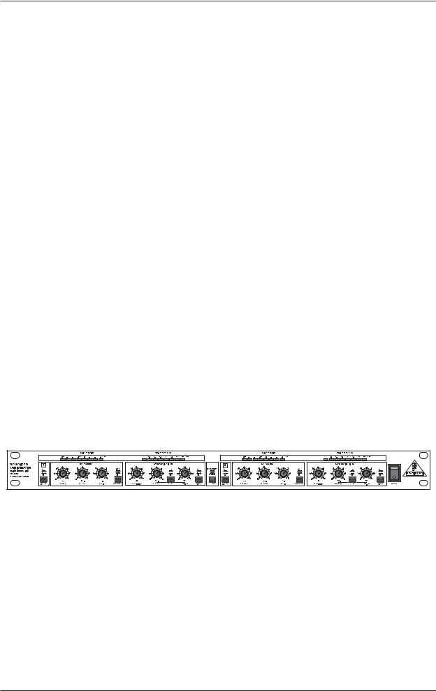
1.3Control elements
Fig. 1.1: Front panel of the DENOISER
The BEHRINGER DENOISER features two identical channels. Each channel is equipped with four push button switches, six rotary controls and 16 LEDs. The COUPLE switch is for stereo tracking.
1. INTRODUCTION |
7 |

DENOISER SNR2000
1.3.1 Front panel
Fig. 1.2: Front panel control elements
1The IN/OUT switch activates the relay and, consequently, the corresponding channel. The unit is bypassed when the switch is not depressed.
2By depressing the COUPLE switch you will tie channel 1 and 2 together for stereo tracking.
+If using the COUPLE switch, it is recommended that all controls be set identically on both channels to ensure proper tracking.
3The EXPANDER IN/OUT switch activates the expander section.
4Use the THRESHOLD control to set the threshold at which low level downward expansion starts. Once the signal falls below this threshold, the amount of expansion increases as the signal level decreases.
5The RELEASE control allows to adjust the desired release time of the expander section.
6Use the RATIO control to adjust the ratio of the downward expansion. Low ratios, from 1.2:1 to about 3:1 produce a more or less slight downward expansion. When, however, the ratio is set to 6:1, the DENOISER functions as noise gate.
7This eight-segment GAIN REDUCTION meter indicates the amount of expansion.
8The FILTER IN/OUT switch activates the filter section.
9The SENSITIVITY control allows you to set the operating level of the dynamic filter relative to the level of the input signal.
10The RELEASE control allows to adjust the desired release time of the filter.
11The CUT OFF control allows to adjust the filter -3 dB point. Thus, the filter can be adapted perfectly to various noise conditions.
12By depressing the AUTO switch, the RELEASE and CUT OFF controls are deactivated. Thus, release time and corner frequency of the filter are automatically derived from the input signal.
13This eight-segment FREQUENCY meter indicates the bandwidth of the filter.
1.3.2Rear panel
Fig. 1.3: Rear panel connectors
14SERIAL NUMBER. Please take the time to complete and return the warranty card within 14 days of the date of purchase, otherwise you will lose the right to the extended warranty. Or just use our onlineregistration (www.behringer.com).
8 |
1. INTRODUCTION |
 Loading...