


 Loading...
EURODESK® MX9000
User´s Manual
Version 1.0 June 2000
ENGLISH
www.behringer.com

SAFETY INSTRUCTIONS
CAUTION: To reduce the risk of electrical shock, do not remove the cover (or back). No user serviceable parts inside; refer servicing to qualified personnel.
WARNING: To reduce the risk of fire or electrical shock, do not expose this appliance to rain or moisture.
This symbol, wherever it appears, alerts you to the presence of uninsulated dangerous voltage inside the enclosure - voltage that may be sufficient to constitute a risk of shock.
This symbol, wherever it appears, alerts you to important operating and maintenance instructions in the accompanying literature. Read the manual.
DETAILED SAFETY INSTRUCTIONS:
All the safety and operation instructions should be read before the appliance is operated.
Retain Instructions:
The safety and operating instructions should be retained for future reference.
Heed Warnings:
All warnings on the appliance and in the operating instructions should be adhered to.
Follow instructions:
All operation and user instructions should be followed.
Water and Moisture:
The appliance should not be used near water (e.g. near a bathtub, washbowl, kitchen sink, laundry tub, in a wet basement, or near a swimming pool etc.).
Ventilation:
The appliance should be situated so that its location or position does not interfere with its proper ventilaton. For example, the appliance should not be situated on a bed, sofa rug, or similar surface that may block the ventilation openings: or placed in a built-in installation, such as a bookcase or cabinet that may impede the flow of air through the ventilation openings.
Heat:
The appliance should be situated away from heat sources such as radiators, heat registers, stoves, or other appliance (including amplifiers) that produce heat.
Power Source:
The appliance should be connected to a power supply only of the type described in the operating instructions or as marked on the appliance.
Grounding or Polarization:
Precautions should be taken so that the grounding or polarization means of an appliance is not defeated.
Power-Cord Protection:
Power supply cords should be routed so that they are not likely to be walked on or pinched by items placed upon or against them, paying particular attention to cords and plugs, convenience receptacles and the point where they exit from the appliance.
Cleaning:
The appliance should be cleaned only as recommended by the manufacturer.
Non-use Periods:
The power cord of the appliance should be unplugged from the outlet when left unused for a long period of time.
Object and Liquid Entry:
Care should be taken so that objects do not fall and liquids are not spilled into the enclosure through openings.
Damage Requiring Service:
The appliance should be serviced by qualified service personnel when:
-The power supply cord or the plug has been damaged; or
-Objects have fallen, or liquid has been spilled into the appliance; or
-The appliance has been exposed to rain; or
-The appliance does not appear to operate normally or exhibits a marked change in performance; or
-The appliance has been dropped, or the enclosure damaged.
Servicing:
The user should not attempt to service the appliance beyond that is described in the Operating Instructions. All other servicing should be referred to qualifield service personnel.
2

FOREWORD
Dear Customer,
Welcome to the team of EURODESK users and thank you very much for expressing your confidence in BEHRINGER products by purchasing the MX9000.
It is one of my most pleasant tasks to write this letter to you, because it is the culmination of many months of hard work delivered by our engineering team to reach a very ambitious goal: making an outstanding device that will become a standard tool used by studios and P.A. companies. The task to design the EURODESK certainly meant a great deal of responsibility, which we assumed by focusing on you, the discerning user and musician. It also meant a lot of work and night shifts to accomplish this goal. But it was fun, too. Developing a product usually brings a lot of people together, and what a great feeling it is when everybody who participated in such a project can be proud of what we’ve achieved.
It is our philosophy to share our joy with you, because you are the most important member of the BEHRINGER family. With your highly competent suggestions for new products you’ve greatly contributed to shaping our company and making it successful. In return, we guarantee you uncompromising quality (manufactured under ISO9000 certified management system) as well as excellent technical and audio properties at an extremely favorable price. All of this will enable you to fully unfold your creativity without being hampered by budget constraints.
We are often asked how we can make it to produce such high-grade devices at such unbelievably low prices. The answer is quite simple: it’s you, our customers! Many satisfied customers means large sales volumes enabling us to get better conditions of purchase for components, etc. Isn’t it only fair to pass this benefit back to you? Because we know that your success is our success, too!
I would like to thank all people whose help on “Project EURODESK MX9000” has made it all possible. Everybody has made very personal contributions, starting from the designers of the unit via the many staff members in our company to you, the user of BEHRINGER products.
My friends, it’s been worth the trouble!
Thank you very much,
Uli Behringer
3
TABLE OF CONTENT
1. THE MANUAL .......................................................................................................................... |
6 |
|
1.1 |
Nomenclature .................................................................................................................................. |
6 |
1.2 |
An un-holstic approach ................................................................................................................... |
6 |
1.3 |
Key ................................................................................................................................................. |
6 |
2. EURODESK OVERVIEW ........................................................................................................ |
6 |
|
2.1 |
Architecture .................................................................................................................................... |
6 |
2.2 |
Metering .......................................................................................................................................... |
7 |
2.3 |
PSU (Power Supply Unit) ................................................................................................................ |
7 |
3. |
INPUT/OUTPUT CHANNEL ................................................................................................... |
8 |
||
|
3.1 |
Channel strip ................................................................................................................................... |
8 |
|
|
3.2 |
Input switching ................................................................................................................................ |
8 |
|
|
3.3 |
Input gain setting ............................................................................................................................ |
9 |
|
|
3.4 |
Main equalizer .............................................................................................................................. |
10 |
|
|
3.5 |
Aux sends .................................................................................................................................... |
10 |
|
|
3.6 |
Routing and muting ........................................................................................................................ |
11 |
|
|
3.7 |
B-channel ..................................................................................................................................... |
12 |
|
4. |
INSERTS ............................................................................................................................... |
13 |
||
5. |
SUBGROUP AND DIRECT OUTPUTS ............................................................................... |
14 |
||
|
5.1 |
Subgroups .................................................................................................................................... |
14 |
|
|
5.2 |
Direct outputs ............................................................................................................................... |
16 |
|
6. |
MASTER PANEL ................................................................................................................... |
16 |
||
|
6.1 |
Aux masters ................................................................................................................................. |
16 |
|
|
|
6.1.1 |
Aux sends .......................................................................................................................... |
16 |
|
|
6.1.2 |
Aux returns ......................................................................................................................... |
17 |
|
6.2 |
MIX-B master ................................................................................................................................ |
19 |
|
|
6.3 |
Monitoring ..................................................................................................................................... |
20 |
|
|
6.4 |
Headphones .................................................................................................................................. |
21 |
|
|
6.5 |
PFL/SOLO .................................................................................................................................... |
22 |
|
|
|
6.5.1 |
PFL .................................................................................................................................... |
22 |
|
|
6.5.1 |
SOLO ................................................................................................................................. |
22 |
|
6.6 |
Talkback ....................................................................................................................................... |
22 |
|
7. |
CONNECTIONS .................................................................................................................... |
23 |
||
|
7.1 |
Rear panel .................................................................................................................................... |
23 |
|
|
7.2 |
Plug soldering guide ...................................................................................................................... |
27 |
|
8. |
THE PATCHFIELD ................................................................................................................ |
30 |
||
|
8.1 |
The normalized bay ....................................................................................................................... |
30 |
|
|
8.2 |
The patchfield ................................................................................................................................ |
30 |
|
|
8.3 |
Looming problems ......................................................................................................................... |
32 |
|
9. |
EQUALIZATION ..................................................................................................................... |
33 |
||
10.GAIN OPTIMIZATION ........................................................................................................... |
34 |
|||
11.IMPEDANCES AND TUNING ............................................................................................... |
35 |
|||
12.(UN)BALANCED LINES ........................................................................................................ |
35 |
|||
|
|
|
|
|
4

13.START-UP ............................................................................................................................. |
37 |
13.1A-channel setting up procedure ..................................................................................................... |
37 |
13.1.1 Selecting inputs .................................................................................................................. |
37 |
13.1.2 Initializing channel for gain-setting ....................................................................................... |
37 |
13.1.3 Auditioning a signal ............................................................................................................. |
37 |
13.2Desk/tape setting up procedures ................................................................................................... |
37 |
13.2.1 Desk normalization ............................................................................................................. |
37 |
13.2.2 Multitrack initialization ........................................................................................................ |
38 |
13.2.3 Recording levels .................................................................................................................. |
38 |
13.2.4 Auditioning a mix ................................................................................................................ |
38 |
13.2.5 Mixer mapping .................................................................................................................... |
38 |
14.8-TRACK MIDI SUITE/DANCE PRODUCTION STUDIO ................................................... |
38 |
14.1Sends ........................................................................................................................................... |
39 |
14.2Auxless headphones mix .............................................................................................................. |
39 |
14.3Returns ......................................................................................................................................... |
40 |
14.4Lining up record/sample inputs ...................................................................................................... |
41 |
14.5Mixdown ....................................................................................................................................... |
41 |
15.16-TRACK RECORDING WITH 2 SAMPLERS ................................................................... |
41 |
15.1Recording ..................................................................................................................................... |
41 |
15.2Headphones .................................................................................................................................. |
42 |
15.3Mixdown ....................................................................................................................................... |
42 |
16.PROFESSIONAL 24-TRACK STUDIO ................................................................................ |
42 |
16.1Recording ..................................................................................................................................... |
42 |
16.2Very tricky headphones ................................................................................................................. |
43 |
16.3Wet monitoring ............................................................................................................................. |
44 |
16.4Mixdown ....................................................................................................................................... |
44 |
17.LIVE P.A. WITH 2-TRACK RECORDING ............................................................................. |
45 |
18.LIVE CONCERT WITH 24-TRACK RECORDING ............................................................... |
46 |
19.EXPANDING THE EURODESK MX9000 ............................................................................. |
48 |
19.1Connections .................................................................................................................................. |
48 |
19.2Alignment ..................................................................................................................................... |
48 |
20.TIMECODE ........................................................................................................................... |
48 |
21.BOUNCING ........................................................................................................................... |
49 |
22.SEQUENCING “LIVE” ......................................................................................................... |
49 |
23.INPUT/OUTPUT CONFIGURATION ................................................................................... |
50 |
24.MODIFICATIONS .................................................................................................................. |
50 |
24.1Aux sends > post EQ ................................................................................................................... |
51 |
24.2MIX-B source > post fader ............................................................................................................. |
51 |
24.3LED meters > pre fader ................................................................................................................. |
51 |
25.SPECIFICATIONS ................................................................................................................. |
52 |
26.WARRANTY ........................................................................................................................... |
54 |
5

1. THE MANUAL
1.1 Nomenclature
Most specialist subjects are not really all that difficult provided you understand the language used, and the vocabulary of mixing is pretty straight-forward. Nevertheless it is as well to be clear about what certain terms mean. A “slot” in a recorder will always be referred to as a TRACK, while that in a mixer will invariably be a CHANNEL. A GROUP will always refer to a submix of channels, never a collection of musicians. Similarly the term BAND will be mentioned only in conjunction with FREQUENCY. We will attempt to be as unambiguous as possible with terms, since much confusion can arise from sloppy definitions.
Some terms can have a plurality of meanings. TRACK, in mixing parlance, refers to a tape recorder. In electronic circuits, components on a PCB (printed circuit board) are linked by flat conductors called TRACKS. Hopefully, where terms have different meanings the contexts will be sufficiently diverse so as to avoid any possible confusion.
1.2 An un-holstic approach
It is virtually impossible to fully explain one aspect of a mixing console (e.g. CHANNEL ROUTING) without also making it clear what those routes are, where they go, are they migratory, etc. That’s why we have compartmentalised the EURODESK manual into sections, making it easy to find problem solving information and advice. You might find that several cross-sectional references have been made, where areas of interest overlap. E.g.: Channel EQ is specified and described in the “Main equalizer” section 3.4, while EQUALIZATION has it’s own section, reflecting it’s importance and weight as a subject in it’s own right.
If we keep repeating ourselves concerning the use of B-channels and the MIX-B bus, it’s because a proper understanding of this area of the board will greatly expand your mixing repertoire.
1.3 Key
All DESK functions will be numbered consistently throughout the manual, whether they be in the text or in an illustration. In addition the following prefixes will be used to denote the various types of function control in any illustrations/text respectively:
Prefix |
Meaning |
S |
Switch |
L |
LED |
P |
Potentiometer |
F |
Fader |
Tab. 1.1: Meaning of the used prefixes
After every prefix you will find the FUNCTION NUMBER. Numbering starts at the top of a CHANNEL, works its way through a stereo GROUP, and finally through the MASTER SECTION. The phantom power and tape operating level switches are not included in the numbering system.
2. EURODESK OVERVIEW
2.1 Architecture
The EURODESK MX9000 is a hybrid SPLIT/INLINE console. Input channels cover most of the surface from the left, while the outputs to tape are to the right. Tape monitor returns, however, are housed within the channel strips, not next to the tape outputs, as would be the case in a conventional “split” design. This architecture
6

enables much flexibility to be bestowed onto the tape monitor signal path, not least being its ability to pick up functions easily from the main channel. Also, during mixdown, when tape tracks are no longer monitored but MIXED, the signal path between tape input and main channel is kept to a minimum.
The configuration is 24 into 8 into 24. This means that there are 24 channels, eight subgroups or “submixes” (or four stereo subgroups) and 24 tape monitor returns, one for each channel. There are 24 100 mm channel faders, eight subgroup faders, and a stereo pair of faders driving the L/R main mix.
In remix mode 48 channels are available, all with EQ and access to the aux buses. There are six additional stereo FX returns, giving a grand total of 60 separate line-level inputs: and that’s before you even consider using the subgroup insert points to provide eight more!
There are six aux buses accessed by four potentiometers, two headphone mixes and professional recording, monitoring and talkback facilities. If you can afford to lose the extra 24 line inputs, the MIX-B bus can also act as a separate stereo aux send, giving eight aux buses in all.
A comprehensive set of inputs and outputs include MIC (+48 V), line, tape (+4 dBu or -10 dBV), inserts all round, direct channel outs and all master recorder and monitoring options. Just about everything you’d expect from a massive console.
In addition, a 1/4" jack expander bay (INPUT ONLY) allows direct patching into all buses within the EURODESK (except PFL and SOLO). Hence two EURODESKs may be linked, or the EURODESK coupled to ANY OTHER CONSOLE, large or small, provided that the other console has (or can be MADE to have) similar access (see section 19 “EXPANDING THE EURODESK”).
Last, and probably least, two BNC connectors on top of the built-in meterbridge await optional gooseneck desk lights, available from all good gooseneck desk light stores. A must for those darkened auditoria, or when you’re into your third consecutive night in the studio.
2.2 Metering
The 1 to 24 channels have signal (-20 dB, L25) and overload LEDs (PEAK, L24).
The bulit-in meterbridge provides 12 segment bargraph meters for all channels and subgroups as well as for the main mix. By the DISPLAY MODE switch (S100, top left of the master section) you decide between CHANNEL and TAPE MODE. Your choice will be indicated by a LED.
In CHANNEL MODE, which is the best for live mixing purposes, the LED meters read the channel’s direct OUTPUT, which is post EQ, post mute and post fader (you may alter that to pre mute and pre fader by the modification described in APPENDIX II.3).
In TAPE MODE the channel meters will mirror the multitrack’s meters, because they read the tape reutrn inputs – after the OPERATING LEVEL switch, but unaffected by anything else happening in the channel. 0 dB is referenced to the selected tape operating level (+4 dBu or -10 dBV).
The main mix meters double up as mono PFL or stereo SOLO meters, or 2-track return meters, or EXTERNAL return meters (in general, what you HEAR is what you SEE). During PFL/SOLO only the main mix bargraph meters illuminate.
+In SOLO/PFL mode a 0 dB meter reading matches an internal operating level of 0 dBu (0.775 V). However, when looking at the mix, 0 dB is referenced to +4 dBu, the 2-track operating level. I.e. if only ONE signal is present in the main mix bus, SOLOing that signal will cause the meter reading to increase by +4 dB.
2.3PSU (Power Supply Unit)
Not an infection of the urinary tract, in fact PSU stands for the least glamorous, most frequently underestimated feature of any electronic device: the POWER SUPPLY UNIT. The EURODESK remote PSU connects to the desk at the rear of the console via a multiway connector. 2 1/2 U high, nevertheless it is designed to slot into a 3U rack space. The extra 1/2 U is to allow air to circulate around the heatsinks employed for heat dissipation. If your control room is small, forget heating. The EURODESK PSU chucks out a massive 400 Watts.
7
Why? Any amplifier circuit is limited in it’s transient response by the available current. In common with most desks of this size, the EURODESK has more than a thousand line-level operational amplifiers (op-amps) inside. When being driven hard, many desks begin to show signs of stress due to power supply limitations. Not so with the EURODESK MX9000. The sound should stay clean and crisp and TIGHT right up to the operating limits of the op-amps themselves.
+Do not connect the PSU to the EURODESK while the PSU is connected to the mains supply.
3. INPUT/OUTPUT CHANNEL
3.1 Channel strip
On the EURODESK MX9000 the 24 INPUT + OUTPUT (I/O or “normal”) channels cover most of the console. Most of each strip is occupied by the main or A-CHANNEL, which can accept MIC, LINE or TAPE inputs, depending on the positions of S1 and S3 (see fig. 3.1 and 3.2). Each channel strip also sports a secondary B-CHANNEL (fig. 3.6) Anything routed to a B-channel is directed to a separate MIX-B bus. (See section 3.7 “B-channel” and also section 6.2 “MIX-B master”).
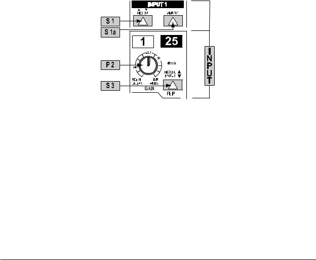
3.2 Input switching
Look first at the MIC/LINE switch S1. In the UP position it selects MIC. In the DOWN position LINE. The next switch S3 chooses whether A-channel looks at INPUT or TAPE. If INPUT is routed to A-channel, TAPE is offered to B-channel. If TAPE is routed to A-channel, INPUT is offered to B-channel. Depressing the PAD switch (S1a) lowers an incoming mic signal by -20 dB, if necessary.
Fig. 3.1: Input
When track laying it is usual to use the MIX-B inputs for monitoring the signal from TAPE, while the A-channels take care of microphones, Dl’s, etc. For MIXING purposes, TAPE tracks are normally “flipped” onto the main channels, leaving the B-channels free for other applications, such as offerinq extra line inputs. These rules are, however, made to be broken.
S23 applies to the B-channel only and replaces the normal TAPE or INPUT source with a tap from the main channel, taken post mute and pre fader. Now MIX-B acts as an extra stereo aux send or extra stereo mix. You should remove MIX-B from the main mix (via S48, master section) in this configuration.
8
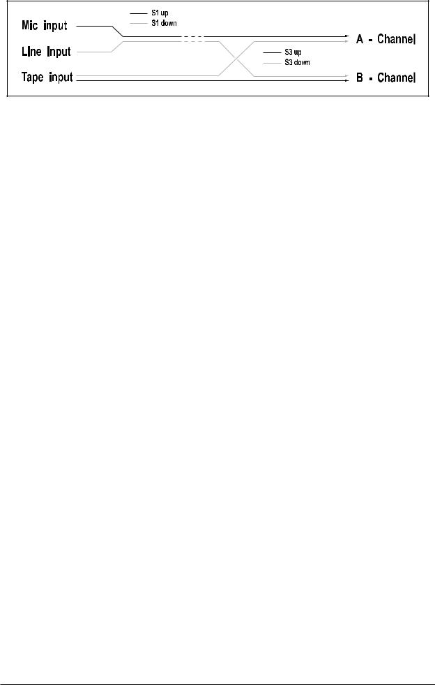
Fig. 3.2: Channel input switching architecture
+The B-channels 25 to 48 are only routable EN BLOC to the main mix, via S48. Therefore the MIX-B bus can only have one function at any one time, either as a stereo AUX or secondary mix send (S48 UP) or as a set of 24 extra line or tape inputs to the main mix (S48 DOWN).
3.3 Input gain setting
The channel input level is set by the TRIMPOT (P2). Use SOLO/PFL (S26) to bring the channel’s input onto the L/R bargraph meters under the master section of the EURODESK MX9000. This also sends the SOLO/ PFLed signal to the left and right speakers. Channel PFL/SOLO (S26) has an associated LED (L26). (See also 13.1 “A-channel setting up procedure” and 6.5 “Solo/PFL”.)
+For level-setting (as opposed to localized listening) choose to use the mono PFL rather than the post fader SOLO bus (S95 DOWN).
+SOLO/PFL never interrupts the mix at the main recording outputs. It follows that aux sends and subgroups must also be unaffected, since they can contribute directly to the main mix.
In addition to switchable PFL/SOLO metering, a couple of LEDs (L24 and L25) continuously monitor whether a signal is present (-20 dB) or the channel is going into overload (PEAK). These take their cue from three test points: input, post EQ and post fader. In all cases the higher level wins. You do NOT want the overload light to come on, or if it does no more than very intermittently during a take or a mix.
9
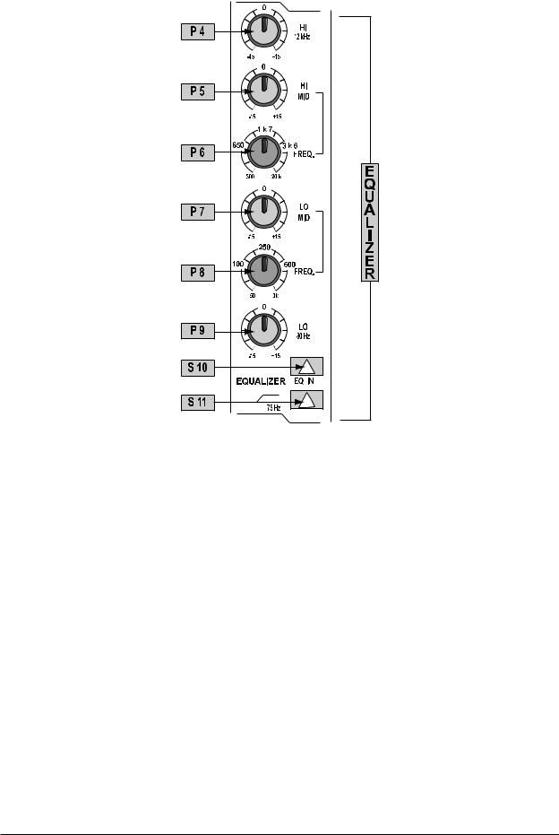
3.4 Main equalizer
Fig. 3.3: Main equalizer
The main equalizer can be switched (S10) out of circuit for easy A/B comparisons between EQed and straight signals, or for when you know you don’t want to use desk EQ at all. It is best considered in three sections. First off there are two Baxendall shelving frequency controls for treble and bass, at 12 kHz and 80 Hz respectively (P4 and P9). These are DUPLICATED for the B-channel (P18 and P19), not merely “SPLIT” off from the main EQ. I.e. you can have a full 4-band EQ on the main channel AND a 2-band EQ on B-channel.
Secondly, there are two semi-parametric swept mids, Q fixed at 1, which cover the bands 300 Hz to 20 kHz and 50 Hz to 3 kHz. An unusually broad frequency range is catered for, and there is an enormous 3-plus octave overlap between the two mid bands (P5, P6, P7 and P8). No experienced engineer will complain about that! All four bands offer 15 dB of cut and boost.
Thirdly there is a steep high pass (lo cut) filter (S11), slope @ 12 dB/octave, -3 dB @ 75 Hz, for reducing floor rumble, plosives, woolly bottom end, etc.
3.5 Aux sends
All six aux sends are mono and post EQ. They are switchable PRE/POST fader in two banks (S13 and S16). For aux sends 1 and 2, two dedicated pots (P12 and P13) are used. These can be taken from a point before or after the channel fader, i.e. PRE or POST (S13). Aux sends 3 and 4, and 5 and 6 are serviced by two potentiometers (P14 and P15). The SHIFT button (S15) determines whether buses 3 and 4 or 5 and 6 are addressed. Also, these four sends can be derived from the main mix or MIX-B, depending on SOURCE (S17), and, as before, can be pre or post (S16).
10
Fig. 3.4: Aux sends
+For almost all FX SEND purposes, you will want auxes to be post fader, so that when a fader level is adjusted, any reverb send from that channel follows the fader. Otherwise, when the fader is pulled down, the reverb from that channel would still be audible. For CUEing purposes, aux sends will usually be set pre fader, i.e. independent of the channel fader (S13 and S16).
+Most reverbs etc. sum internally the left and right inputs. The very few that don’t may be driven in true stereo either by 1) 2 aux sends or 2) the MIX-B bus (see section 3.7 “MIX-B”).
+There is +15 dB of gain on every aux send. Such a high boost is only appropriate where the channel fader is set around -15 dB or lower. Here, an almost exclusively WET signal will be heard. Previously, in most consoles, such a wet mix required the use of a PRE setting for the channel auxiliary send. This meant losing fader control over the signal.
3.6 Routing and muting
ROUTING means selecting which BUS you want a channel to address. There are actually six stereo buses in the EURODESK MX9000 (plus a stereo SOLO bus). The main mix bus is selected by S32 (see figure 3.5), while the subgroups are selected by switches S28 (for groups 1 and 2), S29 (3 and 4), S30 (5 and 6) and S31 (7 and 8). Odd and even numbered groups are selected via the main A-channel PAN P24, as are the left and right mix buses. (The sixth stereo bus is the MIX-B bus, with it’s own independent pan control P20; see section 3.7 “B-channel”). Usually, only one of S28 to S31 will be selected for a particular channel (See block schematics).
+An exception to this rule is when laying down voice takes. It is often convenient to have the mic channel(s) routed to alt potential TAKE tracks simultaneously, since you are often dropping in quickly between four or more tracks. It means one less button press each time you switch tracks.
11
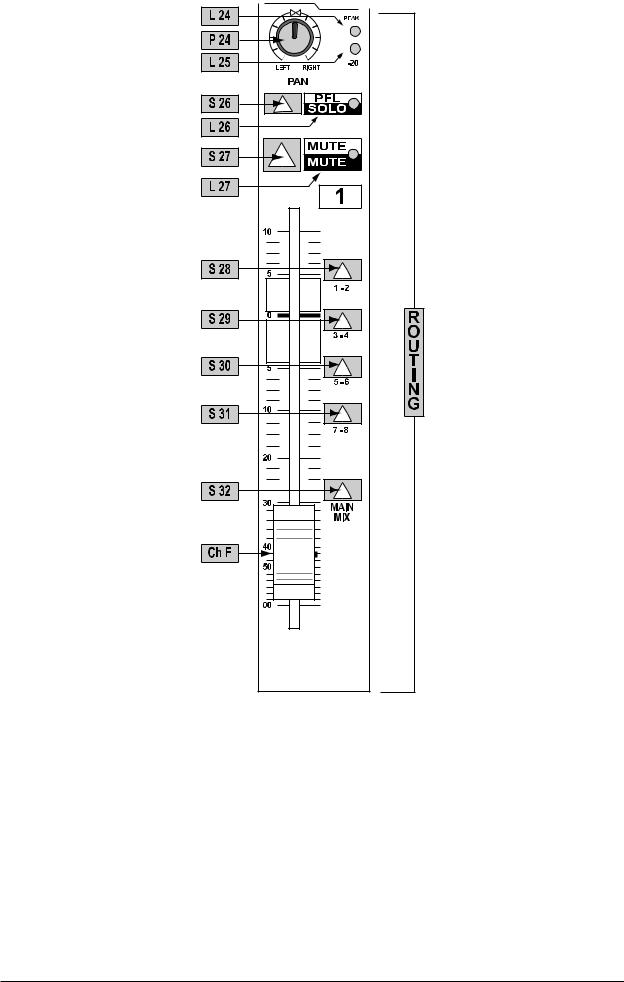
Fig. 3.5: Routing
Level to the subgroup and main mix buses is ultimately determined by the channel faders. These are designed to give a smooth logarithmic taper of a type more usually associated with the name of some pretty expensive brand ... The low level performance particularly is far smoother than that of a normal “budget” fader.
The MUTE button (S27), like that for SOLO has an LED indicator (L27) and removes the A-channel signal from all buses, save any auxes set to pre fader. It is ergonomically placed immediately above the fader and engaging MUTE is equivalent to setting a fader level of minus infinity.
3.7 B-channel
The B-channel (fig 3.6) comprises a secondary channel with it’s own hi and lo EQ, pan and level (P18, P19, P20 and P21). The EQ is a replica of the A-channel shelving EQ. The B-channel ALWAYS feeds into the MIX-B stereo bus, but it’s source can be switched between TAPE, LINE, MIC and A-CHANNEL, depending on how S1, S3 and S23 are set (see fig. 3.2 and section 3.2). Unusually for an 8-bus console, B-channels also
12
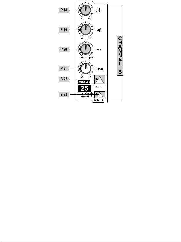
have their own MUTE buttons (S22). Aux sends 3/4/5/6 may be diverted from the A to the B-channel via S17. Therefore if the B-channel is being used to monitor off-tape, some FX processing e.g. reverb and echo can still be applied. (See section 16.3 “Wet monitoring”.)
+When B-channel looks at A-channel (S23 DOWN), the signal comes A-channel mute switch and pre fader. A modification can convert this PRE stereo aux send to POST fader. (See APPENDIX II “Modification No. 2”.)
Fig. 3.6: B-channel |
4. INSERTS
Insert points are useful for adding dynamic processing or equalisation to a channel, subgroup or the mix. Unlike reverbs, etc., which are usually added to the dry signal, dynamic processing is normally applied across an entire signal. Here an aux send would be inappropriate. Instead the signal is intercepted somewhere along the channel/subgroup/mix, fed through the dynamics processor and/or EQ and then returned to the console at the same point where it left. The insert point is invisible or normalized, until a jack is plugged into it.
All subgroups and channels have got insert points, as does the main stereo output. Both SEND and RETURN are accommodated on a single stereo 1/4" jack socket wired tip=send, ring=return. Inserts are always pre fader and also pre EQ / aux sends for channels.
Insert points may also be used as pre EQ direct outputs without interrupting the signal flow. This is obvious when looking at the patchbay wiring (section 8, fig. 8.1). If you want to insert a dynamics processor post EQ, the insert point must either be taken from a subgroup, or via a second channel / aux return as follows:
a)Insert a compressor/gate/EQ across a subgroup, and route the channel to be processed (and only that channel) to that subgroup.
b)Alternatively, patch a channel’s direct out into a compressor/gate/EQ. Take the output from that compressor/ gate/EQ and feed it back into the desk via a secondary input (channel, aux return, etc.).
Figure 4.1 illustrates how you might insert into a channel post EQ for mixdown or track-laying (their requirements are different). Mixdown requires one A and one B-channel. Recording requires two A-channels.
13

Fig. 4.1: Post EQ channel insert
+In this arrangement you might find that compression tends to soften the perceived amount of EQ applied. The solution? Apply more EQ. This creates a real “pressure” sound, great for high energy music such as dance. (For a more subtle approach, use the desk insert points word for word.)
+Using a group insert to effect post EQ processing precludes the use of POSTPROCESSING AUX SENDS without some serious re-patching.
5. SUBGROUP AND DIRECT OUTPUTS
5.1 Subgroups
The principal routes to the multitrack are via the SUBGROUP OUTPUTS. There are four stereo (or eight mono) subgroups, numbered 1 to 8. All main channels can access all of them, as can the STEREO AUX RETURNS 1 and 2. (For this reason it is usually wise to bring your best two FX processors back on these returns (or A-channels, for that matter), so that they can easily be sent to tape. (See also section 6.1 “Aux masters”.)
Why are there 16 subgroup output jacks on the EURODESK when there are only 8 subgroups? Well, each subgroup output is duplicated, so that the EURODESK can interface with up to 16 tracks via the group outputs without having to re-patch.
As well as always functioning as subgroups for track laying via the SUBGROUP OUTPUTS, groups can be routed directly into the main mix bus for submixing. Main mix routing is handled by switches S37 and S38. S37 routes an odd numbered group to the left bus, while S38 sends an even numbered subgroup to the right bus. That’s fine for stereo submixes. If instead you want a pair of mono submixes, press also the MONO buttons (S35 and S36). Now these subgroups feed into the center of the main mix stereo image, i.e. equally to L and R. You could have the first subgroup feeding into the left hand side, while the second one appeared in mono, but I can’t think of many real situations when you’d want to do this.
Subgroup SOLO (S33 + S34) follows the mix assignment. E.g.: if the main mix is selected, then that stereo subgroup will be monitored in stereo. If mono is also selected, monitoring is in mono.
+Try inserting compression / de-essing / an exciter / a gate across grouped signals (e.g. backing vocals, drums, layered synths).
14

Fig. 5.1: Stereo subgroup channel schematic
+Try merging a dry signal with a little wet, then compressing the sum heavily. Though the reverb proportion will be low when a signal is present, the resultant reverb tail pumped up by the compressor at the start of each silence will give the illusion that the reverb was massive alt the time. (The listener will be left wondering how the singer could sound so clear in such a wet acoustic!)
+EURODESK insert points are, of course, simultaneously inputs and outputs. Get them onto a patchbay, where they can appear as independent sockets, and do away with all these fiddly Y-leads that always seem to be the first to get knotted in the flightcase. (See section 8 “Patchfield”.) Now it is possible to do the following incredibly useful patch without having to make up what would amount to a ring-to-tip, tip-to-ring stereo patch lead.
15
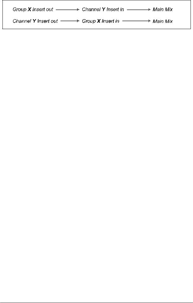
Fig. 5.2: Using insert to add channel EQ to subgroup output (while keeping the number of line inputs unchanged!)
5.2 Direct outputs
Each of the 24 main channels on the EURODESK MX9000 has its own DIRECT OUTPUT, which is taken from a point immediately after the fader (i.e. post EQ and after the aux sends, see block schematics). This can feed a tape track directly without having to resort to the subgroups, enabling more than eight different tracks to be recorded simultaneously. Almost alone among the EUROjacks, these are on unbalanced mono sockets at +4 dB. (See section 23, also section 16.1 “Recording”.)
6. MASTER PANEL
6.1 Aux masters
6.1.1 Aux sends
Much of the master section is taken up by master aux sends and returns. We’ll start with the sends (see fig. 6.1.1).
Stacked in a vertical column are six master aux send levels, one for each of buses 1 to 6 (P41 to P46). Each has a gain structure of minus infinity to +15 dB. The extra 15 dB of gain comes in once a knob passes a center detente (representing the “normal” unity gain position), enabling insensitive outboard FX to be properly driven. Each aux send has a SOLO button (S41 to S46), and, as with other areas of mixer, a LOCAL SOLO LIGHT (L47), which illuminates when any of the AUX master sends are solo-ed. This is to help you see exactly what has been solo-ed. Any experienced engineer will have had occasion to search painstakingly through every solo button on his/her console trying to find out why the main solo light was on, and the control room monitors silent!
16
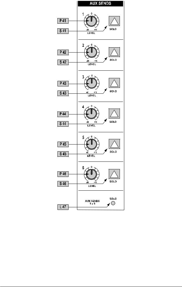
Fig. 6.1: Aux sends
6.1.2 Aux returns
Next to the aux sends are the stereo aux returns (see fig. 6.2). These can be thought of as a dozen extra line inputs configured as six stereo pairs. On these inputs there is up to 20 dB of gain available. Alternatively, a mono (center-panned) signal may be returned by plugging into the left aux return jack only.
+This feature is disabled if all line-level I/Os from the EURODESK are wired permanently to a patchbay (see section 8).
17

^
Fig. 6.2: Stereo aux returns
18
Loading...