


MDX4400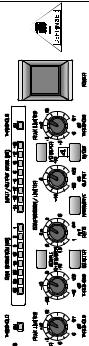
PRO


MULTICOM® |
User’s Manual
Version 1.3 April 2001
www.behringer.com
ENGLISH
MULTICOM PRO MDX4400
SAFETY INSTRUCTIONS
CAUTION: To reduce the risk of electric shock, do not remove the cover (or back). No user serviceable parts inside; refer servicing to qualified personnel.
WARNING: To reduce the risk of fire or electric shock, do not expose this appliance to rain or moisture.
This symbol, wherever it appears, alerts you to the presence of uninsulated dangerous voltage inside the enclosure—voltage that may be sufficient to constitute a risk of shock.
This symbol, wherever it appears, alerts you to important operating and maintenance instructions in the accompanying literature. Read the manual.
DETAILED SAFETY INSTRUCTIONS:
All the safety and operation instructions should be read before the appliance is operated.
Retain Instructions:
The safety and operating instructions should be retained for future reference.
Heed Warnings:
All warnings on the appliance and in the operating instructions should be adhered to.
Follow instructions:
All operation and user instructions should be followed.
Water and Moisture:
The appliance should not be used near water (e.g. near a bathtub, washbowl, kitchen sink, laundry tub, in a wet basement, or near a swimming pool etc.).
Ventilation:
The appliance should be situated so that its location or position does not interfere with its proper ventilation. For example, the appliance should not be situated on a bed, sofa, rug, or similar surface that may block the ventilation openings, or placed in a built-in installation, such as a bookcase or cabinet that may impede the flow of air through the ventilation openings.
Heat:
The appliance should be situated away from heat sources such as radiators, heat registers, stoves, or other appliances (including amplifiers) that produce heat.
Power Source:
The appliance should be connected to a power supply only of the type described in the operating instructions or as marked on the appliance.
Grounding or Polarization:
Precautions should be taken so that the grounding or polarization means of an appliance is not defeated.
Power-Cord Protection:
Power supply cords should be routed so that they are not likely to be walked on or pinched by items placed upon or against them, paying particular attention to cords and plugs, convenience receptacles and the point where they exit from the appliance.
Cleaning:
The appliance should be cleaned only as recommended by the manufacturer.
Non-use Periods:
The power cord of the appliance should be unplugged from the outlet when left unused for a long period of time.
Debris and Liquid Entry:
Care should be taken that debris and/or liquids do not enter the enclosure through openings.
Damage Requiring Service:
The appliance should be serviced by qualified service personnel when:
-The power supply cord or the plug has been damaged; or
-Debris or liquid has entered the appliance; or
-The appliance has been exposed to rain; or
-The appliance does not appear to operate normally or exhibits a marked change in performance; or
-The appliance has been dropped, or the enclosure damaged.
Servicing:
The user should not attempt to service the appliance beyond that which is described in the operating instructions. All other servicing should be referred to qualified service personnel.
2

MULTICOM PRO MDX4400
FOREWORD
Dear Customer,
Welcome to the team of MULTICOM PRO users and thank you very much for expressing your confidence in BEHRINGER products by purchasing this unit.
It is one of my most pleasant tasks to write this letter to you, because it is the culmination of many months of hard work delivered by our engineering team to reach a very ambitious goal: making an outstanding device better still. The MULTICOM has for quite a long time been a standard tool used by numerous studios and PA rental companies. The task to improve one of our best-selling products certainly meant a great deal of responsibility, which we assumed by focusing on you, the discerning user and musician. It also meant a lot of work and night shifts to accomplish this goal. But it was fun, too. Developing a product usually brings a lot of people together, and what a great feeling it is when everybody who participated in such a project can be proud of what we’ve achieved.
It is our philosophy to share our joy with you, because you are the most important member of the BEHRINGER family. With your highly competent suggestions for new products you’ve greatly contributed to shaping our company and making it successful. In return, we guarantee you uncompromising quality (manufactured under the ISO9000 certified management system) as well as excellent technical and audio properties at an extremely favorable price. All of this will enable you to fully unfold your creativity without being hampered by budget constraints.
We are often asked how we can make it to produce such high-grade devices at such unbelievably low prices. The answer is quite simple: it’s you, our customers! Many satisfied customers means large sales volumes enabling us to get better conditions of purchase for components, etc. Isn’t it only fair to pass this benefit back to you? Because we know that your success is our success, too!
I would like to thank all people whose help on “Project MULTICOM PRO” has made it all possible. Everybody has made very personal contributions, starting from the designers of the unit via the many staff members in our company to you, the user of BEHRINGER products.
My friends, it’s been worth the trouble!
Thank you very much,
Uli Behringer
3
MULTICOM PRO MDX4400
MULTICOM® PRO
Interactive 4-channel compressor/limiter/peak limiter of the reference class
sSwitchable highpass filter in control signal path avoids low-frequency signals from dominatingMDX4400compressor action
sCompression characteristics switchable between IKA and “hard knee” characteristics
sIGC (Interactive Gain Control) peak limiter combines clipper with program limiter circuits
sExtremely low-noise operational amplifiers and high-grade VCA’s
sHigh-quality detent potentiometers and backlit switches
sStereo Couple function for channels 1/2 and 3/4 selectable with real totaling of RMS output
sAccurate 8-digit LED meters for input level, output level and gain reduction
sOperating level switchable from +4 dBu to -10 dBV
sServo-balanced inputs and outputs featuring 1/4" jacks and XLR connectors
sManufactured under ISO9000 certified management system
4

MULTICOM PRO MDX4400
TABLE OF CONTENT
1. INTRODUCTION..................................................................................................................... |
6 |
|
1.1 Technical Background ..................................................................................................................... |
7 |
|
1.1.1 |
Noise As A Physical Phenomenon ........................................................................................ |
7 |
1.1.2 |
What Are Audio Dynamics? .................................................................................................. |
7 |
1.1.3 |
Compressors/Limiters ........................................................................................................... |
9 |
2. THE DESIGN CONCEPT ..................................................................................................... |
10 |
|
2.1 |
High Quality Components And Design ........................................................................................... |
10 |
2.2 |
Inputs And Outputs ....................................................................................................................... |
10 |
|
2.2.1 Balanced Inputs And Outputs.............................................................................................. |
10 |
3. INSTALLATION ..................................................................................................................... |
11 |
|
3.1 |
Rack Mounting ............................................................................................................................... |
11 |
3.2 |
Mains Voltage ................................................................................................................................ |
11 |
3.3 |
Audio Connections ......................................................................................................................... |
11 |
3.4 |
Selecting The Operating Level ....................................................................................................... |
12 |
4. CONTROLS .......................................................................................................................... |
13 |
|
4.1 |
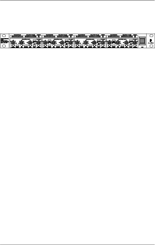
The Front Panel Control Elements ................................................................................................ |
13 |
4.4 |
Rear Panel Control Elements Of The MULTICOM PRO ................................................................. |
15 |
5. APPLICATIONS ..................................................................................................................... |
16 |
|
5.1 |
Compression/Leveling/Limiting/Clipping ......................................................................................... |
16 |
5.2 |
Compressor Section ..................................................................................................................... |
17 |
|
5.2.1 Initial Settings For The Compressor Section ....................................................................... |
18 |
|
5.2.2 The MULTICOM PRO As A Sound Effects Unit .................................................................... |
18 |
|
5.2.3 The “Muffling” Effect Of A Compressor ................................................................................. |
18 |
5.3 |
Peak Limiter Section ..................................................................................................................... |
19 |
|
5.3.1 Initial Settings For The Peak Limiter Section....................................................................... |
19 |
6. SPECIAL APPLICATIONS ..................................................................................................... |
20 |
|
6.1 |
Using The MULTICOM PRO For Recording And Cassette Duplication ........................................... |
20 |
|
6.1.1 The MULTICOM PRO In Digital Recording And Sampling .................................................... |
20 |
|
6.1.2 The MULTICOM PRO In Mastering ...................................................................................... |
20 |
6.2 |
The MULTICOM PRO as a protective device .................................................................................. |
20 |
|
6.2.1 Protection Of A System With A Passive Crossover .............................................................. |
21 |
|
6.2.2 Protection Of A System With An Active Crossover............................................................... |
21 |
|
6.2.3 Improving The Sound Of A Processor System ..................................................................... |
21 |
6.3 |
The MULTICOM PRO In Broadcast ............................................................................................... |
22 |
7. SPECIFICATIONS .................................................................................................................. |
23 |
|
8. WARRANTY ........................................................................................................................... |
25 |
|
5

MULTICOM PRO MDX4400
1. INTRODUCTION
In purchasing the MULTICOM PRO, you have acquired an extremely efficient and universal dynamics processor. The unit was particularly designed for those applications most frequently used in practice. Despite the extremely complex internal circuitry, the unit has a control surface which is clearly laid out and easy to understand. With the MULTICOM PRO, BEHRINGER have developed an innovative and easy-to-use dynamics processor which meets the high demands that are made on such a device both in live and studio applications. The unit’s most outstanding features are the precision and flexibility of its functions.
Quad compressor/limiters are actually not a new invention. Usually, four simple compressor sections are packed into one enclosure, representing however a compromise in terms of operation and functionality. An excessive number of controls complicates the operation of the unit and a lack of control functions restricts the unit’s range of application.
The BEHRINGER MULTICOM PRO is a compact quad compressor/limiter based on the successful BEHRINGER Interactive Technology. Integrated AUTO processors automatically derive attack and release times from the programme material and provide you with transparent and “inaudible” compression. In 1 RU package the unit consists of four independent high-precision compressor sections with sidechain filters and four peak limiters, each offering all the required controls.
With rack space at a premium both in the studio and in sound reinforcement, the MULTICOM PRO’s unique high density design and clean uncluttered layout makes it a truly useful audio tool for all applications. The MULTICOM PRO is a perfect and extremely cost-effective solution for all your multi-channel dynamic applications.
Advanced BEHRINGER Technology
Compared to its predecessors, the MULTICOM PRO offers several advanced features such as the extended LED meters, the sidechain filter, the controlable peak limiter per channel and the couple function for two channels. Additionally, we have succeeded in refining the audio properties as well as the circuit topology.
For the first time, the MULTICOM PRO MDX 4400 uses SMD technology (Surface Mounted Device). These sub-miniature components known from aerospace technology allow for an extreme packing density, plus improve the unit’s reliability.
IKA (Interactive Knee Adaptation) Compressor
Our proven IKA (Interactive Knee Adaptation) circuit successfully combines the concept of a “hard knee” compressor with the characteristics of a “soft knee” approach. This program-dependent regulation scheme forms the prerequisite both for “inaudible” and musical program compression and for creative and highly effective dynamics processing.
With its IKA circuit the MULTICOM PRO is capable of delivering outstanding musical results both in studio and live PA applications.
Additionally, the MULTICOM PRO’s sidechain filter allows for limiting the influence low-frequency signal portions usually have on the control logic, so that the compression ratio is mainly determined by those frequencies that are essential to the loudness perceived by the listener—the midrange frequencies.
AUTO COMPRESSOR Circuitry
The response of a compressor and the quality of dynamics processing largely depend on the control times, i.e., the attack and release functions. In particular, in the field of “musical” compression of complex composite signals, programme-dependent control times are necessary. The interactive AUTO processor derives the attack and release times automatically from the programme material, a function that avoids misadjustment of the control times, which is a problem often encountered in conventional designs. In addition the AUTO processor allows for a high compression of the dynamic range without any audible side effects, such as “pumping”, “breathing” etc.
IGC (Interactive Gain Control) Peak Limiter
A further remarkable feature of the BEHRINGER MULTICOM PRO is the IGC (Interactive Gain Control) Limiter, an intelligent combination of a clipper and a program limiter. Above an adjustable threshold the peak limiter begins to function and restricts signal peaks radically (clipper). If however, the threshold of the limiter was surpassed for more than a few milliseconds, the IGC circuit automatically kicks in and reduces the level of the
6 |
1. INTRODUCTION |

MULTICOM PRO MDX4400
overall output signal so that no audible distortion occurs (program limiter). After the level falls below the threshold, the signal returns to the original value after a period of about 1 second. This IGC circuit proves to be extremely valuable as much for live work (loudspeaker protection) as for digital situations, where any extreme signal peaks would exceed the maximum headroom and therefore would cause severe problems.
+The following instructions should initially familiarize you with the special terms used, so that you can get to know all the functions of the unit. After you have read the instructions carefully, please put them away safely, so that you can refer to them again if necessary.
1.1 Technical Background
By employing current modern analogue technology it is possible to manufacture audio equipment with a dynamic range of up to 125 dB. In contrast to analogue techniques, the dynamic range of digital equipment is approximately 25 dB less. With conventional record and tape recorder technology, as well as broadcasting, this value is further reduced. Generally, dynamic restrictions are due to noisy storage in transmission media and also the maximum headroom of these systems.
1.1.1 Noise As A Physical Phenomenon
All electrical components produce a certain level of inherent noise. Current flowing through a conductor leads to uncontrolled random electron movements. For statistical reasons, this produces frequencies within the whole audio spectrum. If these currents are highly amplified, the result will be perceived as noise. Since all frequencies are equally affected, we term this white noise. It is fairly obvious that electronics cannot function without components. Even if special low-noise components are used, a certain degree of basic noise cannot be avoided.
This effect is similar when replaying a tape. The non-directional magnetic particles passing the replay head can also cause uncontrolled currents and voltages. The resulting sound of the various frequencies is heard as noise. Even the best possible tape biasing can “only” provide signal-to-noise ratios of about 70 dB, which is not acceptable today since the demands of listeners have increased. Due to the laws of physics, improving the design of the magnetic carrier is impossible using conventional means.
1.1.2 What Are Audio Dynamics?
A remarkable feature of the human ear is that it can detect the most wide ranging amplitude changes—from the slightest whisper to the deafening roar of a jet-plane. If one tried to record or reproduce this wide spectrum of sound with the help of amplifiers, cassette recorders, records or even digital recorders (CD, DAT etc.), one would immediately be restricted by the physical limitations of electronic and acoustic sound reproduction technology.
The usable dynamic range of electro-acoustic equipment is limited as much at the low end as at the high end. The thermal noise of the electrons in the components results in an audible basic noise floor and thus represents the bottom limit of the transmission range. The upper limit is determined by the levels of the internal operating voltages; if they are exceeded, audible signal distortion is the result. Although in theory, the usable dynamic range sits between these two limits, it is considerably smaller in practice, since a certain reserve must be maintained to avoid distortion of the audio signal if sudden level peaks occur. Technically speaking, we refer to this reserve as “headroom”—usually this is about 10 - 20 dB. A reduction of the operating level would allow for greater headroom, i.e. the risk of signal distortion due to level peaks would be reduced. However, at the same time, the basic noise floor of the program material would be increased considerably.
1. INTRODUCTION |
7 |
MULTICOM PRO MDX4400
P/dB |
|
|
|
|
|
140 |
|
|
|
|
|
120 |
|
|
|
|
|
100 |
|
|
|
|
|
80 |
MicrophoneAmplifier |
|
|
|
|
60 |
PowerAmplifier |
TapeRecorder |
|
|
|
40 |
Radio |
Cassette Recorder |
|||
Ear |
Fig. 1.1: The dynamic range capabilities of various devices
It is therefore useful to keep the operating level as high as possible without risking signal distortion in order to achieve optimum transmission quality.
It is possible to further improve the transmission quality by constantly monitoring the program material with the aid of a volume fader, which manually levels the material. During low passages the gain is increased, during loud passages the gain is reduced. Of course it is fairly obvious that this kind of manual control is rather restrictive; it is difficult to detect signal peaks and it is almost impossible to level them out. Manual control is simply not fast enough to be satisfactory.
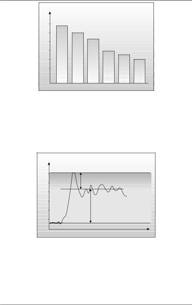
P/dB |
Clipping |
+20 |
Headroom |
0 |
Operating level |
-20 |
-40 |
Effective SNR |
-60 |
-80 |
Noise floor |
t |
Fig. 1.2: The interactive relationship between the operating level and the headroom
The need therefore arises for a fast acting automatic gain control system which will constantly monitor the signals and which will always adjust the gain to maximize the signal-to-noise ratio without incurring signal distortion. This device is called a compressor or limiter. This system is a part of the BEHRINGER MULTICOM PRO.
8 |
1. INTRODUCTION |
 Loading...