


MDX2200


COMPOSER® PRO |
User’s Manual
Version 1.3 June 2001
ENGLISH
www.behringer.com
COMPOSER PRO MDX2200
SAFETY INSTRUCTIONS
CAUTION: To reduce the risk of electric shock, do not remove the cover (or back). No user serviceable parts inside; refer servicing to qualified personnel.
WARNING: To reduce the risk of fire or electric shock, do not expose this appliance to rain or moisture.
This symbol, wherever it appears, alerts you to the presence of uninsulated dangerous voltage inside the enclosure—voltage that may be sufficient to constitute a risk of shock.
This symbol, wherever it appears, alerts you to important operating and maintenance instructions in the accompanying literature. Read the manual.
DETAILED SAFETY INSTRUCTIONS:
All the safety and operation instructions should be read before the appliance is operated.
Retain Instructions:
The safety and operating instructions should be retained for future reference.
Heed Warnings:
All warnings on the appliance and in the operating instructions should be adhered to.
Follow instructions:
All operation and user instructions should be followed.
Water and Moisture:
The appliance should not be used near water (e.g. near a bathtub, washbowl, kitchen sink, laundry tub, in a wet basement, or near a swimming pool etc.).
Ventilation:
The appliance should be situated so that its location or position does not interfere with its proper ventilation. For example, the appliance should not be situated on a bed, sofa, rug, or similar surface that may block the ventilation openings, or placed in a built-in installation, such as a bookcase or cabinet that may impede the flow of air through the ventilation openings.
Heat:
The appliance should be situated away from heat sources such as radiators, heat registers, stoves, or other appliances (including amplifiers) that produce heat.
Power Source:
The appliance should be connected to a power supply only of the type described in the operating instructions or as marked on the appliance.
Grounding or Polarization:
Precautions should be taken so that the grounding or polarization means of an appliance is not defeated.
Power-Cord Protection:
Power supply cords should be routed so that they are not likely to be walked on or pinched by items placed upon or against them, paying particular attention to cords and plugs, convenience receptacles and the point where they exit from the appliance.
Cleaning:
The appliance should be cleaned only as recommended by the manufacturer.
Non-use Periods:
The power cord of the appliance should be unplugged from the outlet when left unused for a long period of time.
Debris and Liquid Entry:
Care should be taken that debris and/or liquids do not enter the enclosure through openings.
Damage Requiring Service:
The appliance should be serviced by qualified service personnel when:
-The power supply cord or the plug has been damaged; or
-Debris or liquid has entered the appliance; or
-The appliance has been exposed to rain; or
-The appliance does not appear to operate normally or exhibits a marked change in performance; or
-The appliance has been dropped, or the enclosure damaged.
Servicing:
The user should not attempt to service the appliance beyond that which is described in the operating instructions. All other servicing should be referred to qualified service personnel.
2

COMPOSER PRO MDX2200
FOREWORD
Dear Customer,
Welcome to the team of COMPOSER PRO users and thank you very much for expressing your confidence in BEHRINGER products by purchasing this unit.
It is one of my most pleasant tasks to write this letter to you, because it is the culmination of many months of hard work delivered by our engineering team to reach a very ambitious goal: making an outstanding device better still. The COMPOSER has for quite a long time been a standard tool used by numerous studios and PA rental companies. The task to improve one of our best-selling products certainly meant a great deal of responsibility, which we assumed by focusing on you, the discerning user and musician. It also meant a lot of work and night shifts to accomplish this goal. But it was fun, too. Developing a product usually brings a lot of people together, and what a great feeling it is when everybody who participated in such a project can be proud of what we’ve achieved.
It is our philosophy to share our joy with you, because you are the most important member of the BEHRINGER family. With your highly competent suggestions for new products you’ve greatly contributed to shaping our company and making it successful. In return, we guarantee you uncompromising quality (manufactured under ISO9000 certified management system) as well as excellent technical and audio properties at an extremely favorable price. All of this will enable you to fully unfold your creativity without being hampered by budget constraints.
We are often asked how we can make it to produce such high-grade devices at such unbelievably low prices. The answer is quite simple: it’s you, our customers! Many satisfied customers means large sales volumes enabling us to get better conditions of purchase for components, etc. Isn’t it only fair to pass this benefit back to you? Because we know that your success is our success, too!
I would like to thank all people whose help on “Project COMPOSER PRO” has made it all possible. Everybody has made very personal contributions, starting from the designers of the unit via the many staff members in my company to you, the user of BEHRINGER products.
My friends, it’s been worth the trouble!
Thank you very much,
Uli Behringer
3
COMPOSER PRO MDX2200
COMPOSER® PRO
Interactive 2-channel expander/gate/compressor/limiter of the reference class
sIKA (Interactive Knee Adaptation) compressor concept combines the advantages of “hard knee” and “soft knee” characteristics MDX2200
sAttack and release times controllable automatically or manually
sSwitchable high-pass filter in control signal path avoids low-frequency signals from dominating compressor action
sCompression characteristics switchable between IKA and “hard knee” characteristics
sIRC circuit in expander/gate allows for “inaudible” elimination of disturbing noise signals
sIGC (Interactive Gain Control) peak limiter combines clipper with program limiter circuits
sExtremely low-noise operational amplifiers and high-grade VCA’s
sHigh-quality detent potentiometers and backlit switches
sStereo couple function selectable with real totaling of RMS output
sAccurate 12-digit LED meters for input level, output level and gain reduction
sTraffic-light function for easy threshold setting
sSwitchable side chain input with side chain monitor function
sOperating level switchable from +4 dBu to -10 dBV
sServo-balanced inputs and outputs featuring 6.3 mm TRS and XLR connectors
sHigh-grade output transformer BEHRINGER OT-1 can be retrofitted
sRelay-controlled hard-bypass switch with auto-bypass function (failsafe relay)
sManufactured under ISO9000 certified management system
4

|
COMPOSER PRO MDX2200 |
|
TABLE OF CONTENTS |
|
|
1. INTRODUCTION..................................................................................................................... |
7 |
|
1.1 |
Before you begin ............................................................................................................................. |
8 |
1.2 |
Design concept ............................................................................................................................... |
8 |
|
1.2.1 High quality components and design ..................................................................................... |
8 |
|
1.2.2 Failsafe relays ...................................................................................................................... |
8 |
|
1.2.3 Balanced inputs and outputs ................................................................................................. |
8 |
|
1.2.4 Transformer balanced outputs (optional) ................................................................................ |
9 |
2. CONTROL ELEMENTS ......................................................................................................... |
9 |
|
2.1 |
Expander/gate section .................................................................................................................... |
9 |
2.2 |
Compressor section ...................................................................................................................... |
10 |
2.3 |
Peak limiter section ....................................................................................................................... |
11 |
2.4 |
Rear panel control elements of the COMPOSER PRO .................................................................. |
12 |
3. TECHNICAL BACKGROUND .............................................................................................. |
12 |
|
3.1 |
Noise as a physical phenomenon.................................................................................................. |
12 |
3.2 |
What are audio dynamics? ........................................................................................................... |
13 |
3.3 |
Compressors/limiters .................................................................................................................... |
14 |
3.4 |
Expanders/noise-gates ................................................................................................................. |
14 |
4. APPLICATIONS ..................................................................................................................... |
15 |
|
4.1 |
Compression/levelling/limiting/clipping ........................................................................................... |
15 |
4.2 |
Expander/gate section .................................................................................................................. |
16 |
|
4.2.1 Controlling leakage in the studio ......................................................................................... |
17 |
|
4.2.2 Initial settings for the expander/gate section ....................................................................... |
17 |
|
4.2.3 Reducing leakage in stage mics ......................................................................................... |
18 |
|
4.2.4 Reducing feedback in stage mics ....................................................................................... |
18 |
|
4.2.5 Noise reduction on effects paths ......................................................................................... |
18 |
|
4.2.6 Creative use of the expander/gate section ........................................................................... |
18 |
4.3 |
Compressor section ...................................................................................................................... |
18 |
|
4.3.1 Initial settings for the compressor section ........................................................................... |
19 |
|
4.3.2 The COMPOSER PRO as a sound effects unit ................................................................... |
20 |
|
4.3.3 The “muffling” effect of a compressor ................................................................................... |
20 |
4.4 |
Peak limiter section ...................................................................................................................... |
20 |
|
4.4.1 Initial settings for the peak limiter section ........................................................................... |
21 |
5. SPECIAL APPLICATIONS ..................................................................................................... |
21 |
|
5.1 |
Using the COMPOSER PRO for recording and cassette duplication ............................................. |
21 |
|
5.1.1 The COMPOSER PRO in digital recording and sampling .................................................... |
22 |
|
5.1.2 The COMPOSER PRO in mastering ................................................................................... |
22 |
5.2 |
The COMPOSER PRO as a protective device ............................................................................... |
22 |
|
5.2.1 Protection of a system with a passive crossover ................................................................. |
23 |
|
5.2.2 Protection of a system with an active crossover .................................................................. |
23 |
|
5.2.3 Improving the sound of a processor system ........................................................................ |
23 |
5.3 |
The COMPOSER PRO in broadcast ............................................................................................. |
23 |
5

|
COMPOSER PRO MDX2200 |
|
6. EXTERNAL SIDE CHAIN APPLICATIONS........................................................................... |
24 |
|
6.1 |
The side chain function ................................................................................................................. |
24 |
6.2 |
Using an equalizer in the side chain path ..................................................................................... |
24 |
|
6.2.1 The COMPOSER PRO as a “de-esser” ............................................................................... |
24 |
|
6.2.2 Frequency-selective filtering of unwanted signals ................................................................ |
25 |
|
6.2.3 Suppressing instruments during recording........................................................................... |
25 |
|
6.2.4 Emphasizing musical instruments during recording ............................................................. |
25 |
6.3 |
Anticipated compression ............................................................................................................... |
25 |
6.4 |
“Voice-over” compression (“ducking”) ............................................................................................. |
26 |
6.5 |
Triggering additional sounds from a rhythm track........................................................................... |
26 |
7. INSTALLATION ..................................................................................................................... |
26 |
|
7.1 |
Rack mounting .............................................................................................................................. |
26 |
7.2 |
Audio connections ........................................................................................................................ |
26 |
7.3 |
Selecting the operating level.......................................................................................................... |
27 |
8. SPECIFICATIONS .................................................................................................................. |
28 |
|
9. WARRANTY ........................................................................................................................... |
30 |
|
6

COMPOSER PRO MDX2200
1. INTRODUCTION
In purchasing the new COMPOSER PRO MDX 2200, you have acquired an extremely efficient and universal dynamics processor, which combines the most commonly used dynamic functions within a compact stereo unit: every channel has its own independent compressor/limiter, an expander/gate and a peak limiter. The precision and flexibility of the functions are the main outstanding features of this high end unit.
Despite the extremely complex internal circuitry, the unit has a control surface which is clearly laid out and easy to understand. The internal design of the unit, together with its external side-chain path, gives the user unsurpassed creative flexibility when processing sound.
Advanced BEHRINGER technology
Compared to its predecessors, the COMPOSER PRO offers several advanced features such as the extended LED meters for ease of operation when setting the threshold, the adjustable expansion ratio in the expander/ gate section and the side chain filter. Additionally, we have succeeded in refining the audio properties as well as the circuit topology.
For the first time, the COMPOSER PRO MDX 2200 uses SMD technology (Surface Mounted Device). These sub-miniature components known from aerospace technology allow for an extreme packing density, plus improve the unit’s reliability.
IKA (Interactive Knee Adaption) compressor
Our proven IKA (Interactive Knee Adaptation) circuit successfully combines the concept of a “hard knee” compressor with the characteristics of a “soft knee” approach. This program-dependent regulation scheme forms the prerequisite both for “inaudible” and musical program compression and for creative and highly effective dynamics processing.
With its IKA circuit the COMPOSER PRO is capable of delivering outstanding musical results both in studio and live PA applications.
Additionally, the COMPOSER PRO’s side-chain filter allows for limiting the influence low-frequency signal portions usually have on the control logic, so that the compression ratio is mainly determined by those frequencies that are essential to the loudness perceived by the listener—the midrange frequencies.
IRC (Interactive Ratio Control) expander
A basic problem in the use of a compressor is the fact that the noise floor is highly amplified during quiet sections or when there are music pauses. This effect is exaggerated when the compression ratio is inappropriate. In order to eliminate this problem, one would normally use an additional expander or gate. The noise is then simply faded out in the quiet sections. However, simple expanders, even when they are used correctly, drastically cut signals below the preset threshold. This effect becomes more noticeable during the transition from signal to noise floor. This can mean, that the start or end of words can be cut on a vocal track.
A newly developed IRC (Interactive Ratio Control) expander has been integrated into the COMPOSER PRO the ratio of which, is automatically adjusted, depending on the program material. The result is an expander which is less critical of adjustment and which is more tolerant in the presence of those signals which appear slightly above the noise floor. Because of its new IRC circuit design, the BEHRINGER COMPOSER PRO expander/ gate section can be used as an independent unit to eradicate noise offering almost limitless possibilities within this application.
IGC (Interactive Gain Control) peak limiter
A further remarkable feature of the BEHRINGER COMPOSER PRO is the IGC (Interactive Gain Control) limiter, an intelligent combination of a clipper and a program limiter. Above an adjustable threshold the peak limiter begins to function and restricts signal peaks radically (clipper). If however, the threshold of the limiter was surpassed for more than a few milliseconds, the IGC circuit automatically kicks in and reduces the level of the overall output signal so that no audible distortion occurs (program limiter). After the level falls below the threshold, the signal returns to the original value after a period of about 1 second. This IGC circuit proves to be extremely valuable as much for live work (loudspeaker protection) as for digital situations, where any extreme signal peaks would exceed the maximum headroom and therefore would cause severe problems. The following instructions should initially familiarize you with the special terms used, so that you can get to know all the functions of the unit. After you have read the instructions carefully, please put them away safely, so that you can refer to them again if necessary.
1. INTRODUCTION |
7 |

COMPOSER PRO MDX2200
1.1 Before you begin
The BEHRINGER COMPOSER PRO MDX2200 was carefully packed in the factory, in order to ensure safe transport. Nevertheless, should the box show signs of damage please check the equipment itself immediately for any signs of external damage.
+If the unit is damaged, please do not return it to us, but notify your dealer and the shipping company immediately, otherwise claims for damage or replacement may not be granted. Shipping claims must be made by the consignee.
Be sure that there is enough space around the unit for cooling and please do not place the COMPOSER PRO on high-temperature devices such as power amplifiers, etc. to avoid overheating.
+Before connecting the COMPOSER PRO to the mains, please carefully check that your equipment is set to the correct supply voltage!
The fuse holder on the female mains connector has 3 triangular markings. Two of these triangles are opposite each other. The MDX2200 is set to the operating voltage shown next to these markings. It can be set to another voltage by turning the fuse holder through 180°. CAUTION: this does not apply to export models, which were designed e.g. only for a mains voltage of 115 V!
Connection to the mains is made by means of a mains cable with an IEC receptacle which complies with the appropriate safety regulations.
+Please note that all units must be grounded properly. For your own safety, you should never remove any ground connectors from electrical devices or power cords or render them inoperative.
1.2 Design concept
1.2.1 High quality components and design
The philosophy behind BEHRINGER products guarantees a no-compromise circuit design and employs the best choice of components. The operational amplifiers NJM4580 which are used in the COMPOSER PRO, are exceptional. They boast extreme linearity and very low distortion characteristics. The most important aspect of the COMPOSER PRO design is a radical VCA implementation which results in outstanding technical specification and excellent performance. To complement this design the choice of components includes high tolerance resistors and capacitors, detent potentiometers, gold plated relay contacts and several other stringently selected elements.
For the first time, the COMPOSER PRO MDX 2200 uses SMD technology (Surface Mounted Device). These sub-miniature components known from aerospace technology allow for an extreme packing density, plus the unit’s reliability could be improved. Additionally, the unit is manufactured in compliance with a ISO9000 certified management system.
1.2.2 Failsafe relays
Failsafe relays have been incorporated into the design of the BEHRINGER COMPOSER PRO, which automatically and silently bypass the unit in the event of power supply disconnection or failure. These relays are also active at switch-on to isolate the COMPOSER PRO until the power rails have settled, thus preventing the possibility of a potentially damaging switch-on thump.
1.2.3 Balanced inputs and outputs
As standard, the BEHRINGER COMPOSER PRO is installed with electronically servo-balanced inputs and outputs. The new circuit design features automatic hum and noise reduction for balanced signals and thus allows for trouble-free operation, even at high operating levels. Externally induced mains hum etc. will be effectively suppressed. The automatic servo-function recognizes the presence of unbalanced connectors and adjusts the nominal level internally to avoid level differences between the input and output signals (correction 6 dB).
8 |
1. INTRODUCTION |

COMPOSER PRO MDX2200
1.2.4 Transformer balanced outputs (optional)
In contrast to electronic balancing, the use of transformer-balanced outputs offers the advantage of galvanic separation between units. Electrical potential differences and ground loops in audio installations do not therefore impair the performance of the units. The transformer-balanced outputs, commonly used in radio and TV engineering, can also be fitted retrospectively upon request. The BEHRINGER transformer OT-1 is designed to the highest exacting standards and is available as an accessory.
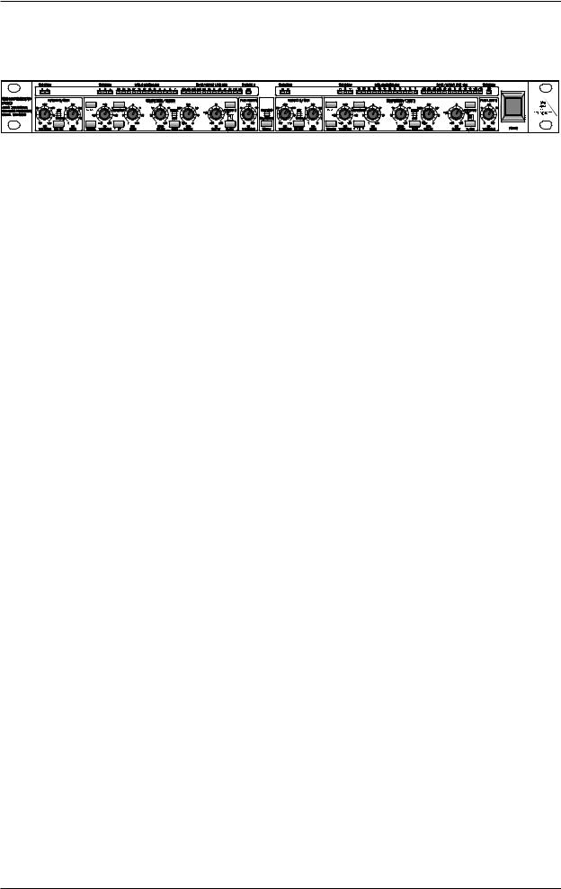
2. CONTROL ELEMENTS
1
Fig. 2.1: COMPOSER PRO front panel
The BEHRINGER COMPOSER PRO has two identical channels. Each channel is equipped with eight backlit push-buttons, eight rotary controls and 30 LED’s. The COUPLE switch is for stereo operation:
1By engaging the COUPLE switch the COMPOSER PRO is converted to stereo mode, where the controls of the left channel take over the control of both audio channels. The control signal for the control characteristic consists of either the sum of the left and right audio signal or the sum of the external audio signals, which are being fed into both SC RETURN connectors. By pressing the COUPLE switch, you override all the controls and switches of channel 2 with the exception of the IN/OUT, SC EXT, SC MON, SC FILTER and I/O METER switches. As a result, the controls of channel 1 take over the functions of channel 2.
+Should you wish to use the SC EXT function in stereo mode, then be sure that both SC RETURN connectors are connected to the external control signal, and that the SC EXT switches on both channels are engaged.
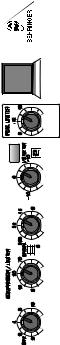
2.1 Expander/gate section
Fig. 2.2: Control elements of expander/gate section
2Use the THRESHOLD control to determine the threshold point below which expansion occurs. The range of this control is from OFF to +15 dB.
2. CONTROL ELEMENTS |
9 |
 Loading...