


DSP1124P |
DESTROYER® PRO |
FEEDBACK |
User’s Manual
Version 1.0 February 2001
ENGLISH
www.behringer.com

FEEDBACK DESTROYER PRO DSP1124P
SAFETY INSTRUCTIONS
CAUTION: To reduce the risk of electrical shock, do not remove the cover (or back). No user serviceable parts inside; refer servicing to qualified personnel.
WARNING: To reduce the risk of fire or electrical shock, do not expose this appliance to rain or moisture.
This symbol, wherever it appears, alerts you to the presence of uninsulated dangerous voltage inside the enclosure - voltage that may be sufficient to constitute a risk of shock.
This symbol, wherever it appears, alerts you to important operating and maintenance instructions in the accompanying literature. Read the manual.
DETAILED SAFETY INSTRUCTIONS:
All the safety and operation instructions should be read before the appliance is operated.
Retain Instructions:
The safety and operating instructions should be retained for future reference.
Heed Warnings:
All warnings on the appliance and in the operating instructions should be adhered to.
Follow instructions:
All operation and user instructions should be followed.
Water and Moisture:
The appliance should not be used near water (e.g. near a bathtub, washbowl, kitchen sink, laundry tub, in a wet basement, or near a swimming pool etc.).
Ventilation:
The appliance should be situated so that its location or position does not interfere with its proper ventilation. For example, the appliance should not be situated on a bed, sofa rug, or similar surface that may block the ventilation openings, or placed in a built-in installation, such as a bookcase or cabinet that may impede the flow of air through the ventilation openings.
Heat:
The appliance should be situated away from heat sources such as radiators, heat registers, stoves, or other appliance (including amplifiers) that produce heat.
Power Source:
The appliance should be connected to a power supply only of the type described in the operating instructions or as marked on the appliance.
Grounding or Polarization:
Precautions should be taken so that the grounding or polarization means of an appliance is not defeated.
Power-Cord Protection:
Power supply cords should be routed so that they are not likely to be walked on or pinched by items placed upon or against them, paying particular attention to cords and plugs, convenience receptacles and the point where they exit from the appliance.
Cleaning:
The appliance should be cleaned only as recommended by the manufacturer.
Non-use Periods:
The power cord of the appliance should be unplugged from the outlet when left unused for a long period of time.
Object and Liquid Entry:
Care should be taken so that objects do not fall and liquids are not spilled into the enclosure through openings.
Damage Requiring Service:
The appliance should be serviced by qualified service personnel when:
-The power supply cord or the plug has been damaged; or
-Objects have fallen, or liquid has been spilled into the appliance; or
-The appliance has been exposed to rain; or
-The appliance does not appear to operate normally or exhibits a marked change in performance; or
-The appliance has been dropped, or the enclosure damaged.
Servicing:
The user should not attempt to service the appliance beyond that is described in the Operating Instructions. All other servicing should be referred to qualified service personnel.
2

FEEDBACK DESTROYER PRO DSP1124P
FOREWORD
Dear Customer,
Welcome to the team of FEEDBACK DESTROYER PRO users and thank you very much for expressing your confidence in BEHRINGER products by purchasing the DSP1124P. It is one of my most pleasant tasks to write this letter to you, because it is the culmination of many months of hard work delivered by our engineering team to reach a very ambitious goal: making an outstanding and extremely flexible device for studios and P.A. rental companies better still.
The task to design our new FEEDBACK DESTROYER PRO certainly meant a great deal of responsibility, which we assumed by focusing on you, the discerning user and musician. It also meant a lot of work and night shifts to accomplish this goal. But it was fun, too. Developing a product usually brings a lot of people together, and what a great feeling it is when everybody who participated in such a project can be proud of what we’ve achieved.
It is our philosophy to share our joy with you, because you are the most important member of the BEHRINGER family. With your highly competent suggestions for new products you’ve greatly contributed to shaping our company and making it successful. In return, we guarantee you uncompromising quality (manufactured under ISO9000 certified management system) as well as excellent technical and audio properties at an extremely favorable price. All of this will enable you to fully unfold your creativity without being hampered by budget constraints.
We are often asked how we can make it to produce such high-grade devices at such unbelievably low prices. The answer is quite simple: it’s you, our customers! Many satisfied customers means large sales volumes enabling us to get better conditions of purchase for components, etc. Isn’t it only fair to pass this benefit back to you? Because we know that your success is our success, too!
I would like to thank all people whose help on “Project FEEDBACK DESTROYER PRO” has made it all possible. Everybody has made very personal contributions, starting from the designers of the unit via the many staff members in our company to you, the user of BEHRINGER products.
My friends, it’s been worth the trouble!
Thank you very much,
Uli Behringer
3
FEEDBACK DESTROYER PRO DSP1124P
FEEDBACK DESTROYER® PRO
24-Bit Dual Engine Digital Feedback Destroyer / Parametric EQ Model DSP1124P
sUltra-high performance 2-channel digital Feedback Destroyer / parametric EQ poweredDSP1124Pby a 24-bit high-speed DSP
s24-bit A/D and D/A converters with 64/128 times oversampling for ultra-high headroom and resolution
sAutomatically and “intelligently” searches out and destroys up to 12 frequencies per channel
s24 fully programmable parametric filters that can be set manually or via MIDI
s“Set-and-forget” default setting enables immediate and super-easy Feedback Destroyer performance
sSingle-Shot mode automatically searches and destroys feedback and locks the filter until you reset it manually
sAuto mode continuously monitors the mix, resetting programmed filters automatically
sManual mode allows for setting up to 2 x 12 fully parametric filters including frequency, bandwidth and gain
sSingle-Shot, Auto and Manual modes are assignable for each filter
sFree FEEDBACK DESTROYER design software allows for total remote control via PC (download at www.behringer.com)
sTwo digital processing engines give you independent or coupled functions on left and right channels
sServo-balanced inputs and outputs on gold plated XLR and 1/4" TRS connectors for high signal integrity
sInternal 24-bit processing with professional 46 kHz sampling rate
sFull MIDI capability and user preset memories to store programs for instant recall
sAccurate eight-segment LED level meters simplify level setting for optimum performance
s“Future-proof” software-upgradeable architecture
sHigh-quality components and exceptionally rugged construction ensure long life and durability
sInternal power supply design for professional application
sManufactured under ISO9000 certified management system
4

FEEDBACK DESTROYER PRO DSP1124P
TABLE OF CONTENTS
1. INTRODUCTION..................................................................................................................... |
6 |
|
1.1 |
The design concept ......................................................................................................................... |
6 |
1.2 |
Before you begin ............................................................................................................................. |
6 |
1.3 |
Background: How is feedback produced? ........................................................................................ |
7 |
|
1.3.1 Background: front of house mix (FOH) .................................................................................. |
7 |
|
1.3.2 Background: monitor mix ...................................................................................................... |
7 |
2. |
APPLICATIONS ....................................................................................................................... |
8 |
|
|
2.1 |
Level setting .................................................................................................................................... |
8 |
|
2.2 |
Using the FEEDBACK DESTROYER PRO in the monitor path ....................................................... |
8 |
|
2.3 |
Using the FEEDBACK DESTROYER PRO in the FOH mix ............................................................ |
9 |
|
2.4 |
Using the FEEDBACK DESTROYER PRO in a studio environment .............................................. |
10 |
3. |
A FEW QUICK STEPS TO ELIMINATE FEEDBACK .......................................................... |
10 |
|
4. |
CONTROL ELEMENTS ....................................................................................................... |
10 |
|
5. |
DSP1124P ARCHITECTURE: PRESETS, FILTERS, OPERATING |
|
|
|
MODES .................................................................................................................................. |
13 |
|
|
5.1 |
“Priming” the DSP1124P for P.A. and monitor applications ............................................................ |
13 |
6. |
OPERATING MODES OF THE DSP1124P.......................................................................... |
14 |
|
|
6.1 |
Off mode “OF” ............................................................................................................................... |
14 |
|
6.2 |
Manual filters (“PA”) / parametric equalizer .................................................................................... |
14 |
|
6.3 |
Automatic filters (“SI” and “AU”)..................................................................................................... |
14 |
|
6.4 |
Locked mode (“LO”) ...................................................................................................................... |
15 |
7. |
WORKING WITH PRESETS................................................................................................. |
15 |
|
|
7.1 |
Recalling Presets .......................................................................................................................... |
15 |
|
7.2 |
Selecting the filter operating mode ................................................................................................ |
15 |
|
7.3 |
Editing filter parameters ................................................................................................................ |
16 |
|
7.4 |
Storing presets .............................................................................................................................. |
16 |
|
7.5 |
Restoring the factory presets ........................................................................................................ |
16 |
8. |
PROBLEMS DO HAVE A CAUSE ... ..................................................................................... |
17 |
|
9. |
MIDI CONTROL .................................................................................................................... |
17 |
|
10.INSTALLATION ..................................................................................................................... |
18 |
||
|
10.1Audio connections ........................................................................................................................ |
18 |
|
|
10.2MIDI connections .......................................................................................................................... |
20 |
|
11.APPENDIX ............................................................................................................................. |
20 |
||
|
11.1 Frequency chart ............................................................................................................................ |
20 |
|
|
11.2 Preset table .................................................................................................................................. |
21 |
|
|
11.3 MIDI implementation ..................................................................................................................... |
22 |
|
12.SPECIFICATIONS ................................................................................................................. |
23 |
||
13.WARRANTY ........................................................................................................................... |
24 |
||
5

FEEDBACK DESTROYER PRO DSP1124P
1. INTRODUCTION
Thank you very much for expressing your confidence in BEHRINGER products by purchasing the FEEDBACK DESTROYER PRO DSP1124P. With the FEEDBACK DESTROYER PRO you have acquired a highly useful device for the control of sound reinforcement systems, which will enable you to focus your attention on what is essential: your music. The fully featured DSP1124P not only suppresses feedback but also incorporates a wealth of additional functions in one single unit. Its 24 separate filters can be edited in all parameters, and automatically detect and suppress feedback frequencies. With its pro-level internal processing circuitry, the unit can also be used as a high-end equalizer for stage and studio applications. The MIDI interface allows for integrating the DSP1124P into any MIDI system, and the open system architecture enables you to update the system software whenever you want. In short: the DSP1124P will be your reliable “workhorse” over many years to come.
+This manual first describes the terminology used, so that you can fully understand the FEEDBACK DESTROYER PRO and its functions. Please read the manual carefully and keep it for future reference.
1.1 The design concept
The philosophy behind BEHRINGER products guarantees a no-compromise circuit design and employs the best choice of components. A 24-bit DSP is used as the heart of the FEEDBACK DESTROYER PRO, which belongs to the best components available owing to its outstanding specifications and excellent sonic characteristics. What is more, high-quality 24-bit A/D and D/A converters ensure the accurate processing of all signals. Additionally, the FEEDBACK DESTROYER uses high-quality resistors and capacitors with very tight tolerances, high-grade switches, and further selected components.
The FEEDBACK DESTROYER PRO employs SMD technology (Surface Mounted Device). These subminiature components known from aerospace technology allow for an extreme packing density and improve the unit’s reliability even further. Additionally, the DSP1124P was manufactured in compliance with an ISO9000 certified management system.
1.2 Before you begin
Your FEEDBACK DESTROYER PRO was carefully packed in the factory and the packaging was designed to protect the unit from rough handling. Nevertheless, we recommend that you carefully examine the packaging and its contents for any signs of physical damage, which may have occurred in transit.
+If the unit is damaged, please do not return it to us, but notify your dealer and the shipping company immediately, otherwise claims for damage or replacement may not be granted. Shipping claims must be made by the consignee.
The BEHRINGER FEEDBACK DESTROYER PRO requires one standard 19" unit of rack space. Please allow at least an additional 4" depth for the connectors on the back panel.
Be sure that there is enough space around the unit for cooling and please do not place the FEEDBACK DESTROYER PRO on high-temperature devices such as power amplifiers, etc. to avoid overheating.
+Before you connect your FEEDBACK DESTROYER PRO to the mains, please make sure that your local voltage matches the voltage required by the unit:
The fuse holder on the female mains connector has 3 triangular markings, with two of these triangles opposing each other. The FEEDBACK DESTROYER PRO is set to the operating voltage printed next to these markers and can be set to another voltage by turning the fuse holder by 180°. CAUTION: This instruction does not apply to export models exclusively designed, e.g. for 115-V operation!
Please use the enclosed power cord to connect the unit to the mains. The cord complies with all applicable safety standards.
6 |
1. INTRODUCTION |
FEEDBACK DESTROYER PRO DSP1124P
+Please note that all units must be grounded properly. For your own safety, you should never remove any ground connectors from electrical devices or power cords or render them inoperative.
As a standard, the BEHRINGER FEEDBACK DESTROYER PRO is equipped with electronically servo-balanced inputs and outputs. The circuit design features automatic hum and noise reduction for balanced signals and thus allows for trouble-free operation, even at high operating levels. Externally induced mains hum, etc. will be effectively suppressed. The automatic servo-function recognizes the presence of unbalanced connectors and adjusts the nominal level internally to avoid level differences between the input and output signals (6-dB correction).
The MIDI interfaces IN, OUT, and THRU are on standardized DIN connectors. Data are transmitted via potential-free opto couplers.
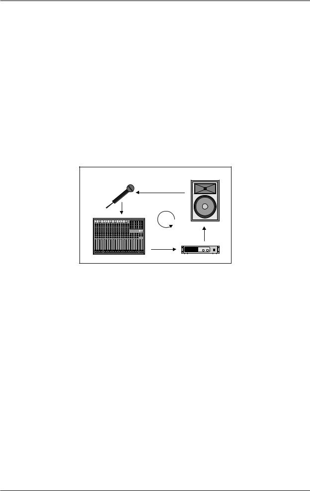
1.3Background: How is feedback produced?
A feedback loop is produced when a microphone signal is reproduced by an amplification system and is subsequently picked up again (with identical phase) by the microphone. If this happens repeatedly, such a feedback loop can become ever more persistent.
Fig. 1.1: How a feedback loop is produced
1.3.1 Background: front of house mix (FOH)
There are two main sections in any sound reinforcement system, which are liable to produce feedback: the first section is the so-called front of house mix (FOH), i.e. the “public address” mix, which is reproduced by one or several amplifiers plus several loudspeakers directed at the audience.
1.3.2 Background: monitor mix
The monitor mix, which is often derived from the same console, feeds one or several stage-mount monitor speakers. Unlike FOH systems, stage monitors are used to provide the individual musicians with a monitor signal, because it is often difficult to hear oneself or each other on the stage, which can be due to the high volume levels produced by the FOH systems, or to different volume levels of the stage-mount instruments and amplifiers. It is therefore not unusual to give each musician his or her own monitor speaker, which is why there are usually several monitor speakers placed along the stage. This is the only way to provide each musician with a directed and focused monitor signal. In an ideal situation, each monitor provides a specific mix, comprising e.g. vocals, drums and keyboards, for each individual musician on the stage.
Unfortunately, it is anything but easy to find perfect positions for the various stage monitors, because the distance between speaker and microphone must be kept very short, which in turn increases the risk of feedback.
+In contrast to FOH systems, it is common practice to create two or even more dedicated monitor mixes, which also involves the use of several monitor speakers. Again, this can lead to increased feedback.
1. INTRODUCTION |
7 |

FEEDBACK DESTROYER PRO DSP1124P
2. APPLICATIONS
The DSP1124P is used exclusively to eliminate feedback in FOH and monitor mixes. Before you go on, please note the following two remarks:
+The FEEDBACK DESTROYER PRO is not intended to be connected directly to the microphones! If this is unavoidable, then we recommend our proven BEHRINGER SHARK DSP110 instead, which is equipped with a dedicated microphone preamplifier.
+No processing device can undo the mistakes made when placing the microphones! So, when you set up your mics, use them according to their directivity and feedback susceptibility (see chapter 8 “PROBLEMS DO HAVE A CAUSE ...”).
2.1 Level setting
Take care to set levels properly on the DSP1124P, so as to successfully employ the FEEDBACK DESTROYER PRO to remove feedback. Use the LED LEVEL METER  . Make sure that the top Clip LEDs flicker only rarely, but never light up all the time.
Low levels deteriorate the dynamics of the music signal, which results in a poor, weak and noisy sound. On the other hand, excess levels overdriving the converters in the FEEDBACK DESTROYER PRO should also be avoided. Digital distortion is (unlike its analog counterpart) very unpleasant to hear as it does not occur gradually but abruptly.
2.2 Using the FEEDBACK DESTROYER PRO in the monitor path
Your DSP1124P is equipped with two channels. In Couple mode (see control elements 

 and
and 

 ), these two channels are linked. But you can also use them separately, for example, to protect two dedicated monitor paths against feedback.
Monitor mixes are realized either via the pre-fader Aux Sends on an FOH console, or via a (usually stagemount) monitor mixer. When using an additional monitor mixer on the stage, you need a so-called splitter to route the single microphone signals both to the FOH console and to the monitor mixer. When using the FOH console for the monitor mix, the stage microphones are connected directly to the console (if necessary, via a so-called stage box).
In both cases, separate monitor mixes are created for the musicians, which can then be provided from the console outputs (usually via the Aux Send outputs). Owing to its 2-channel design, your FEEDBACK DESTROYER PRO allows you to protect two monitor paths against feedback. To do so, connect the pre-fader Aux Send outputs on your console to the inputs of the DSP1124 (as shown in fig. 2.1). Then, connect the inputs of the monitor power amps to the outputs of the FEEDBACK DESTROYER PRO (see fig. 2.1).
As already mentioned, monitor paths are particularly susceptible to feedback. When vocal microphones are not installed in a fixed position, things become even worse, so it really makes sense to protect the monitor paths against feedback. Another positive side effect of using the DSP1124P in the monitor path is the fact that you can raise the volume levels considerably.
As you can see, your DSP1124P is a perfect tool to protect two independent monitor paths. But why is that so important? Because “monitoring” is a complex task. Usually, each monitor path is used for an independent mix comprising a variety of signal sources. This is the only way to ensure that each performer on the stage can hear exactly what he or she wants.
+Owing to its 2-channel design, the DSP1124P is the perfect tool for application in two separate monitor paths. However, if you need to protect four monitors against feedback, we recommend that you use a second DSP1124P.
+If possible, all monitor paths should be set pre-fader, as this leaves the monitor mix unaffected from any changes made to the FOH mix.
8 |
2. APPLICATIONS |
 Loading...