


FBQ1000
Table of contents
 Loading...
User Manual
FEEDBACK DESTROYER FBQ1000
Automatic and Ultra-Fast Feedback Destroyer/Parametric EQ
with 24 FBQ Filters

2 FEEDBACK DESTROYER FBQ1000 User Manual
Table of Contents
Thank you .......................................................................2
Important Safety Instructions ...................................... 3
Legal Disclaimer ............................................................. 3
Limited warranty ............................................................ 3
1. Introduction ............................................................... 4
2. Applications ............................................................... 5
3. A Few Quick Steps to EliminateFeedback .............. 6
4. Control Elements ....................................................... 6
5. FBQ1000 Architecture:
Presets, Filters, Operating Modes ................................ 7
6. Operating Modes of the FBQ1000 ............................ 8
7. Working with Presets ................................................8
8. Problems Do Have A Cause ... ................................. 10
9. MIDI Control ............................................................. 10
10. Installation ............................................................. 11
11. Appendix ................................................................12
12. Specications ......................................................... 15
Thank you
Thank you very much for expressing your condence in BEHRINGER products by
purchasing the FEEDBACK DESTROYER FBQ1000. With the FEEDBACK DESTROYER
you have acquired a highly useful device for the control of sound reinforcement
systems, which will enable you to focus your attention on what is essential:
your music. The fully featured FBQ1000 not only suppresses feedback but also
incorporates a wealth of additional functions in one single unit. Its 24 separate
lters can be edited in all parameters, and automatically detect and suppress
feedback frequencies. With its pro-level internal processing circuitry, the unit can
also be used as a high-end equalizer for stage and studio applications. The MIDI
interface allows for integrating the FBQ1000 into any MIDI system, and the open
system architecture enables you to update the system software whenever you
want. In short: the FBQ1000 will be your reliable “workhorse” over many years
tocome.
3 FEEDBACK DESTROYER FBQ1000 User Manual
9. Do not defeat the safety purpose of the polarized
TO BIND MUSICGROUP BY ANY EXPRESS OR IMPLIED
Important Safety Instructions
Terminals marked with this symbol carry
electrical current of su cient magnitude
to constitute risk of electric shock.
Use only high-quality professional speaker cables with
¼" TS or twist-locking plugs pre-installed. Allother
installation or modi cation should be performed only
by quali edpersonnel.
This symbol, wherever it appears,
alertsyou to the presence of uninsulated
dangerous voltage inside the
enclosure-voltage that may be su cient to constitute a
risk ofshock.
This symbol, wherever it appears,
alertsyou to important operating and
maintenance instructions in the
accompanying literature. Please read the manual.
Caution
To reduce the risk of electric shock, donot
remove the top cover (or the rear section).
No user serviceable parts inside. Refer servicing to
quali ed personnel.
Caution
To reduce the risk of re or electric shock,
do not expose this appliance to rain and
moisture. The apparatus shall not be exposed to dripping
or splashing liquids and no objects lled with liquids,
suchas vases, shall be placed on the apparatus.
Caution
These service instructions are for use
by quali ed ser vice personnel only.
Toreduce the risk of electric shock do not perform any
servicing other than that contained in the operation
instructions. Repairs have to be performed by quali ed
servicepersonnel.
or grounding-type plug. A polarized plug has two blades
with one wider than the other. A grounding-type plug
has two blades and a third grounding prong. The wide
blade or the third prong are provided for your safety. Ifthe
provided plug does not t into your outlet, consult an
electrician for replacement of the obsolete outlet.
10. Protect the power cord from being walked on or
pinched particularly at plugs, convenience receptacles,
and the point where they exit from the apparatus.
11. Use only attachments/accessories speci ed by
themanufacturer.
12. Use only with the
cart, stand, tripod, bracket,
or table speci ed by the
manufacturer, orsold with
the apparatus. When a cart
is used, use caution when
moving the cart/apparatus
combination to avoid
injury from tip-over.
13. Unplug this apparatus during lightning storms or
when unused for long periods of time.
14. Refer all servicing to quali ed service personnel.
Servicing is required when the apparatus has been
damaged in any way, such as power supply cord or plug
is damaged, liquid has been spilled or objects have fallen
into the apparatus, the apparatus has been exposed
to rain or moisture, does not operate normally, or has
beendropped.
15. The apparatus shall be connected to a MAINS socket
outlet with a protective earthing connection.
16. Where the MAINS plug or an appliance coupler is
used as the disconnect device, the disconnect device shall
remain readily operable.
UNDERTAKING OR REPRESENTATION. THIS MANUAL
IS COPYRIGHTED. NO PART OF THIS MANUAL MAY
BE REPRODUCED OR TRANSMITTED IN ANY FORM
OR BY ANY MEANS, ELECTRONIC OR MECHANICAL,
INCLUDING PHOTOCOPYING AND RECORDING OF ANY
KIND, FOR ANY PURPOSE, WITHOUT THE EXPRESS
WRITTEN PERMISSION OF MUSICGROUPIPLTD.
ALL RIGHTS RESERVED.
© 2013 MUSICGroupIPLtd.
Trident Chambers, Wickhams Cay, P.O. Box 146,
Road Town, Tortola, British Virgin Islands
LIMITED WARRANTY
For the applicable warranty terms and conditions
and additional information regarding MUSIC Group’s
Limited Warranty, please see complete details online at
www.music-group.com/warranty.
1. Read these instructions.
2. Keep these instructions.
3. Heed all warnings.
4. Follow all instructions.
5. Do not use this apparatus near water.
6. Clean only with dry cloth.
7. Do not block any ventilation openings. Install in
accordance with the manufacturer’s instructions.
8. Do not install near any heat sources such as
radiators, heat registers, stoves, or other apparatus
(including ampli ers) that produce heat.
LEGAL DISCLAIMER
TECHNICAL SPECIFICATIONS AND APPEARANCES
ARE SUBJECT TO CHANGE WITHOUT NOTICE AND
ACCURACY IS NOT GUARANTEED. BEHRINGER,
KLARKTEKNIK, MIDAS, BUGERA, AND TURBOSOUND
ARE PART OF THE MUSIC GROUP MUSICGROUP.COM.
ALL TRADEMARKS ARE THE PROPERTY OF THEIR
RESPECTIVE OWNERS. MUSICGROUP ACCEPTS NO
LIABILITY FOR ANY LOSS WHICH MAY BE SUFFERED
BY ANY PERSON WHO RELIES EITHER WHOLLY OR
IN PART UPON ANY DESCRIPTION, PHOTOGRAPH
OR STATEMENT CONTAINED HEREIN. COLORS AND
SPECIFICATIONS MAY VARY FROM ACTUAL PRODUCT.
MUSIC GROUP PRODUCTS ARE SOLD THROUGH
AUTHORIZED FULLFILLERS AND RESELLERS ONLY.
FULLFILLERSAND RESELLERS ARE NOT AGENTS OF
MUSICGROUP AND HAVE ABSOLUTELY NO AUTHORITY
4 FEEDBACK DESTROYER FBQ1000 User Manual
1. Introduction
1.1 The design concept
The philosophy behind BEHRINGER products guarantees a no-compromise
circuit design and employs the best choice of components. A 24-bit DSP is
used as the heart of the FEEDBACK DESTROYER, which belongs to the best
components available owing to its outstanding specications and excellent sonic
characteristics. What is more, high-quality 24-bit A/D and D/A converters ensure
the accurate processing of all signals. Additionally, the FEEDBACK DESTROYER
uses high-quality resistors and capacitors with very tight tolerances, high-grade
switches, and further selected components.
The FEEDBACK DESTROYER employs SMD technology (Surface Mounted Device).
These subminiature components known from aerospace technology allow for
an extreme packing density and improve the unit’s reliability even further.
Additionally, the FBQ1000 was manufactured in compliance with an ISO9000
certied management system.
1.2 Before you begin
Your FEEDBACK DESTROYER was carefully packed in the factory and
the packaging was designed to protect the unit from rough handling.
Nevertheless,werecommend that you carefully examine the packaging and its
contents for any signs of physical damage, which may have occurred in transit.
◊ If the unit is damaged, please do not return it to us, but notify your
dealer and the shipping company immediately, otherwise claims for
damage or replacement may not be granted. Shipping claims must be
made by the consignee.
The BEHRINGER FEEDBACK DESTROYER requires one standard 19" unit of
rack space. Please allow at least an additional 4" depth for the connectors on the
backpanel.
Be sure that there is enough space around the unit for cooling and please do not
place the FEEDBACK DESTROYER on high-temperature devices such as power
ampliers, etc. to avoid overheating.
◊ Before you connect your FEEDBACK DESTROYER to the mains,
please make sure that your local voltage matches the voltage required
by the unit:
The fuse holder on the female mains connector has 3 triangular markings, with
two of these triangles opposing each other. The FEEDBACK DESTROYER is set to the
operating voltage printed next to these markers and can be set to another voltage
by turning the fuse holder by 180°. CAUTION: This instruction does not apply to
export models exclusively designed, e.g. for 115-V operation!
Please use the enclosed power cord to connect the unit to the mains. The cord
complies with all applicable safety standards.
◊ Please note that all units must be grounded properly. For your own
safety, you should never remove any ground connectors from electrical
devices or power cords or render them inoperative.
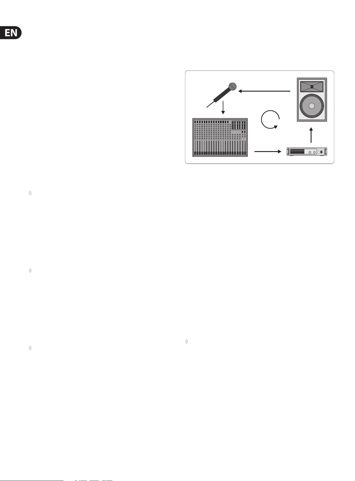
1.3 Background: How is feedback produced?
A feedback loop is produced when a microphone signal is reproduced by an
amplication system and is subsequently picked up again (with identical phase)
by the microphone. If this happens repeatedly, such a feedback loop can become
ever more persistent.
Fig. 1.1: How a feedback loo p is produced
1.3.1 Background: front of house mix (FOH)
There are two main sec tions in any sound reinforcement system, which are liable
to produce feedback: the rst section is the so-called front of house mix (FOH),
i.e. the “public address” mix, which is reproduced by one or several ampliers
plus several loudspeakers directed at the audience.
1.3.2 Background: monitor mix
The monitor mix, which is often derived from the same console, feeds one or
several stage-mount monitor speakers. Unlike FOH systems, stage monitors
are used to provide the individual musicians with a monitor signal, because it
is often dicult to hear oneself or each other on the stage, which can be due
to the high volume levels produced by the FOH systems, or to dierent volume
levels of the stage-mount instruments and ampliers. It is therefore not unusual
to give each musician his or her own monitor speaker, which is why there are
usually several monitor speakers placed along the stage. This is the only way to
provide each musician with a directed and focused monitor signal. In an ideal
situation, eachmonitor provides a specic mix, comprising e.g. vocals, drums and
keyboards, foreach individual musician on the stage.
Unfortunately, it is anything but easy to nd perfect positions for the various
stage monitors, because the distance between speaker and microphone must be
kept very short, which in turn increases the risk of feedback.
◊ In contrast to FOH systems, it is common practice to create two or even
more dedicated monitor mixes, which also involves the use of several
monitor speakers. Again, this can lead to increased feedback.
As a standard, the BEHRINGER FEEDBACK DESTROYER is equipped with
electronically servo-balanced inputs and outputs. The circuit design features
automatic hum and noise reduction for balanced signals and thus allows for
trouble-free operation, even at high operating levels. Externally induced mains
hum, etc. will be eectively suppressed. The automatic servo-function recognizes
the presence of unbalanced connectors and adjusts the nominal level internally
to avoid level dierences between the input and output signals (6-dB correction).
The MIDI interfaces IN, OUT, and THRU are on standardized DIN connectors.
Dataare transmitted via potential-free opto couplers.
5 FEEDBACK DESTROYER FBQ1000 User Manual
2. Applications
The FBQ1000 is used exclusively to eliminate feedback in FOH and
monitormixes.
Before you go on, please note the following two remarks:
◊ The FEEDBACK DESTROYER is not intended to be connected directly
to the microphones! If this is unavoidable, then we recommend our
proven BEHRINGER SHARK FBQ100 instead, which is equipped with a
dedicated microphone preamplifier.
◊ No processing device can undo the mistakes made when placing the
microphones! So, when you set up your mics, use them according to
their directivity and feedback susceptibility (see chapter 8 “Problems
Do Have A Cause ...”).
2.1 Level setting
Take care to set levels properly on the FBQ1000, so as to successfully employ
the FEEDBACK DESTROYER to remove feedback. Use the LED LEVEL METER (1).
Makesure that the top Clip LEDs icker only rarely, but never light up all the time.
Low levels deteriorate the dynamics of the music signal, which results in a
poor, weak and noisy sound. On the other hand, excess levels overdriving the
converters in the FEEDBACK DESTROYER should also be avoided. Digitaldistortion
is (unlike its analog counterpart) very unpleasant to hear as it does not occur
gradually but abruptly.
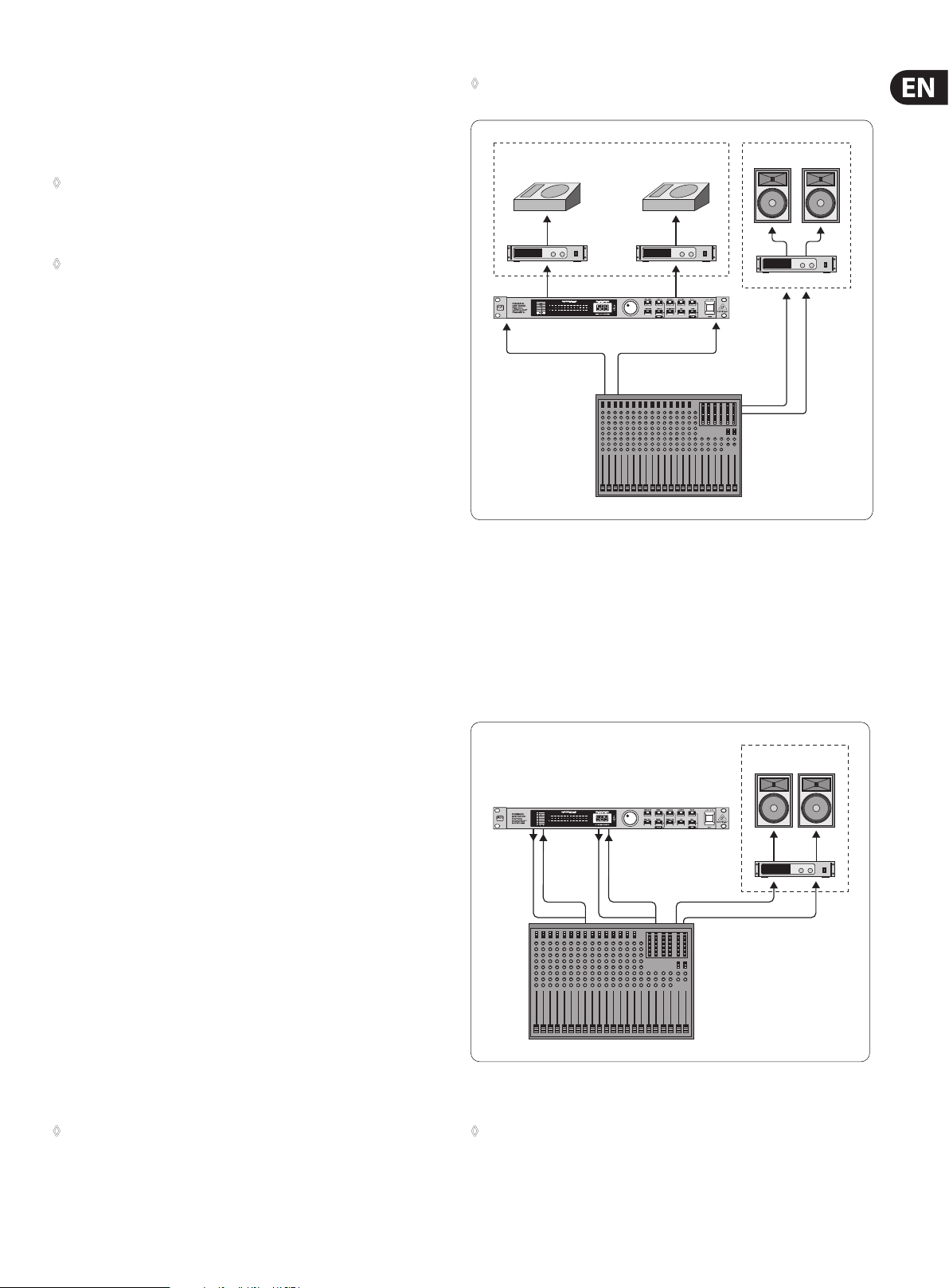
2.2 Using the FEEDBACK DESTROYER in the
monitor path
Your FBQ1000 is equipped with two channels. In Couple mode (see control
elements (8) and (9) ), these two channels are linked. But you can also
use them separately, for example, to protect two dedicated monitor paths
againstfeedback.
Monitor mixes are realized either via the pre-fader Aux Sends on an FOH console,
or via a (usually stage-mount) monitor mixer. When using an additional monitor
mixer on the stage, you need a so-called splitter to route the single microphone
signals both to the FOH console and to the monitor mixer. When using the FOH
console for the monitor mix, the stage microphones are connected directly to the
console (if necessary, via a so-called stage box).
◊ If possible, all monitor paths should be set pre-fader, as this leaves the
monitor mix unaf fected from any changes made to the FOH mix.
Monitor System
Monitor 1
Power Amp
Output 1
Input 1
Pre-Fader
Aux Send 1
Fig. 2.1: Using the FBQ1000 in th e monitor sends
Monitor 2
(Mono)
Output 2
Input 2
Pre-Fader
Aux Send 2
P.A. System
Master
Out
2.3 Using the FEEDBACK DESTROYER
in the FOH mix
Since you want to make sure that deliberately produced feedback signals, such as
“guitar feedback”, are not eliminated, you should tr y inserting the FBQ1000 into
those channels that are susceptible to feedback. For example, you could process
a vocal microphone that is liable to produce feedback by connecting the FBQ1000
to the insert points of the respective channel.
P.A. System
In both cases, separate monitor mixes are created for the musicians, which can
then be provided from the console outputs (usually via the Aux Send outputs).
Owing to its 2-channel design, your FEEDBACK DESTROYER allows you to protect
two monitor paths against feedback. To do so, connect the pre-fader Aux Send
outputs on your console to the inputs of the FBQ1000 (as shown in g.2.1).
Then,connect the inputs of the monitor power amps to the outputs of the
FEEDBACK DESTROYER (see g. 2.1).
As already mentioned, monitor paths are particularly susceptible to feedback.
When vocal microphones are not installed in a xed position, things become even
worse, so it really makes sense to protect the monitor paths against feedback.
Another positive side eect of using the FBQ1000 in the monitor path is the fact
that you can raise the volume levels considerably.
As you can see, your FBQ1000 is a perfect tool to protect two independent
monitor paths. But why is that so important? Because “monitoring” is a complex
task. Usually, each monitor path is used for an independent mix comprising a
variety of signal sources. This is the only way to ensure that each performer on
the stage can hear exactly what he or she wants.
◊ Owing to its 2-channel design, the FBQ1000 is the perfect tool for
application in two separate monitor paths. However, if you need to
protect four monitors against feedback, we recommend that you use a
second FBQ1000.
Outp. 1 Inp. 1
Outp. 2
Channel
Insert
Fig. 2.2: Using the FBQ1000 for specic mics (connecting the FEEDBACK DESTROYER in either channel
or sub-group inserts)
Inp. 2
Channel
Insert
Master Out
◊ When processing a microphone signal with the FBQ1000 and a
compressor inserted into the same channel insert point, the FEEDBACK
DESTROYER should always be used pre-compressor: in this way,
the signal is taken at the insert jack, passes the FBQ1000, then the
compressor, and is finally routed back to the insert jack.
6 FEEDBACK DESTROYER FBQ1000 User Manual
Ideally, your mixer has sub-groups with dedicated insert points to connect
the FBQ1000! Route all channels that are susceptible to feedback (e.g. all vocal
mics) to one sub-group. While the other signals (e.g. line level signals, low-level
instrumental mics) pass unaected, all critical microphone channels are
monitored by the FBQ1000.
If your mixer has no sub-group inserts, we recommend that you connect the
FBQ1000 as follows: connect the sub-group output to one input on the FBQ1000,
and the corresponding output to a free line input of a mixing console channel
or one of the Aux Return inputs on the console. As long as ENGINE L and ENGINE
R are not linked, you would even have the second channel of your FEEDBACK
DESTROYER free for other applications (e.g. channel inserts).
2.4 Using the FEEDBACK DESTROYER
in a studio environment
With its highly exible conguration the FBQ1000 also delivers good results in a
professional studio or home recording environment, as it provides a maximum of
12 fully parametric equalizers per channel in Parametric EQ mode. Thus, you can
realize any application ranging from slight processing to the total manipulation
of music signals. For example, you can use the FBQ1000 as an equalizer for your
studio monitors or to enhance the EQs in your mixing console, as these are often
only semi-parametric.
3. A Few Quick Steps to
EliminateFeedback
Irrespective of whether you need the FBQ1000 to protect the FOH or the monitor
mix against feedback, the following procedure is always the same and should be
done before the concer t, so as to eliminate basic feedback problems right before
the show begins:
• Check the setting of the OPERATING LEVEL switch on the rear of the unit.
For most P.A. systems, this switch should be set to +4 dB. In doubt,
pleaseconsult the user’s manual of your mixing console. Always make sure
that the audio signal levels are set correctly (see control element (1))
• Switch on the unit, and use the JOG WHEEL (rotary control) to select preset1.
The preset table (see table 11.3) lists the various FBQ1000 presets available
• Using the FBQ1000 in the monitor path: Turn up the Aux Send or Mon.
controls in the rst mic channel, until the microphone starts to produce
feedback. If more than one monitor paths is being used, this procedure must
be done separately for each path. Repeat for each susceptible mic channel
• Using the FBQ1000 on channel/sub-group inserts: Deliberately induce
feedback by setting the channel/sub-group faders to 0 dB and raising the
gain controls for the individual microphones in turn
In either case, the FEEDBACK DESTROYER will suppress feedback as soon as it is
produced—the corresponding LED will stop ashing and stay lit. The various edit
options available are described in chapter 7. But don’t let us do the second step
before the rst:
4. Control Elements
The BEHRINGER FEEDBACK DESTROYER is equipped with ten parameter keys,
one JOG WHEEL (rotary control) and a numeric LED DISPLAY. By means of an
8-segment LED meter, each of the two fully independent channels can be
monitored. Each of the 24 lters has one LED assigned to it, which informs about
the status of the lter.
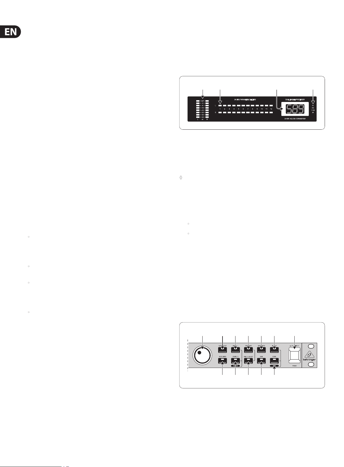
(1) (2) (4)(3)
Fig. 4.1: Display sect ion of the FEEDBACK DEST ROYER
(1) The LED METER is used to monitor the output level. Each channel has eight
LEDs assigned to it. When the Clip LED lights up frequently, this warns you
of digital distortion. If the FBQ1000 is set to Total Bypass mode (see (14)),
thelevel meter reads the input level.
◊ Please always use appropriate level settings, as this is essential for
successful feedback elimination.
(2) The FBQ1000 features 24 lters, i.e. 12 lters per channel. These lters
can be monitored conveniently with the STATUS INDICATOR next to the
Display. 12LEDs inform you about the status of the lters on each channel
(left/right). Aconstantly lit LED signals the following conditions:
• A lter has been “set”, i.e. it is already suppressing feedback; or
• A lter is set to Parametric EQ mode (gain ≠ 0 dB)
Cyclically ashing LEDs signal that a lter is searching feedback frequencies
in Single-Shot or Auto mode (see chapters 5 and 6.3). Inactive lters (“OF”)
and lters in Parametric EQ mode (see 6.2), with a gain setting of 0 dB,
areindicated by unlit LEDs.
(3) The LED DISPLAY consists of a clearly visible, two-digit numeric
display. After power-up, it reads the number of the last preset used.
Additionally,theLED-DISPLAY shows the absolute values of the parameters
that are beingedited.
(4) The INDICATORS to the right of the DISPLAY (Hz, kHz, 1/60 and dB)
lightup when you edit the associated parameters in Edit mode. For example,
whenyou raise the level of a lter, the “dB” indicator lights up.
(5) (6)
(8) (10) (12) (14) (16)
(7) (9) (11) (13) (15)
Fig. 4.2: Func tion keys and Jog Wh eel
Loading...