


ULTRA-CURVE® PRO DSP8024
User’s Manual
Version 1.2 June 2001
ENGLISH
www.behringer.com
ULTRA-CURVE PRO DSP8024
SAFETY INSTRUCTIONS
CAUTION: To reduce the risk of electric shock, do not remove the cover (or back). No user serviceable parts inside; refer servicing to qualified personnel.
WARNING: To reduce the risk of fire or electric shock, do not expose this appliance to rain or moisture.
This symbol, wherever it appears, alerts you to the presence of uninsulated dangerous voltage inside the enclosure—voltage that may be sufficient to constitute a risk of shock.
This symbol, wherever it appears, alerts you to important operating and maintenance instructions in the accompanying literature. Read the manual.
DETAILED SAFETY INSTRUCTIONS:
All the safety and operation instructions should be read before the appliance is operated.
Retain instructions:
The safety and operating instructions should be retained for future reference.
Heed warnings:
All warnings on the appliance and in the operating instructions should be adhered to.
Follow instructions:
All operation and user instructions should be followed.
Water and moisture:
The appliance should not be used near water (e.g. near a bathtub, washbowl, kitchen sink, laundry tub, in a wet basement, or near a swimming pool etc.).
Ventilation:
The appliance should be situated so that its location or position does not interfere with its proper ventilaton. For example, the appliance should not be situated on a bed, sofa rug, or similar surface that may block the ventilation openings: or placed in a built-in installation, such as a bookcase or cabinet that may impede the flow of air through the ventilation openings.
Heat:
The appliance should be situated away from heat sources such as radiators, heat registers, stoves, or other appliances (including amplifiers) that produce heat.
Power source:
The appliance should be connected to a power supply only of the type described in the operating instructions or as marked on the appliance.
Grounding or polarization:
Precautions should be taken so that the grounding or polarization means of an appliance is not defeated.
Power-cord protection:
Power supply cords should be routed so that they are not likely to be walked on or pinched by items placed upon or against them, paying particular attention to cords and plugs, convenience receptacles and the point where they exit from the appliance.
Cleaning:
The appliance should be cleaned only as recommended by the manufacturer.
Non-use periods:
The power cord of the appliance should be unplugged from the outlet when left unused for a long period of time.
Object and liquid entry:
Care should be taken so that objects do not fall and liquids are not spilled into the enclosure through openings.
Damage requiring service:
The appliance should be serviced by qualified service personnel when:
-the power supply cord or the plug has been damaged; or
-objects have fallen, or liquid has been spilled into the appliance; or
-the appliance has been exposed to rain; or
-the appliance does not appear to operate normally or exhibits a marked change in performance; or
-the appliance has been dropped, or the enclosure damaged.
Servicing:
The user should not attempt to service the appliance beyond that which is described in the operating instructions. All other servicing should be referred to qualified service personnel.
2
ULTRA-CURVE PRO DSP8024
FOREWORD
Dear Customer,
welcome to the team of ULTRA-CURVE PRO users and thank you very much for expressing your confidence in BEHRINGER products by purchasing this unit.
It is one of my most pleasant tasks to write this letter to you, because it is the culmination of many months of hard work delivered by our engineering team to reach a very ambitious goal: making an outstanding device better still. The ULTRA-CURVE has for quite a long time been a standard tool used by numerous studios and PA rental companies. The task to improve one of our best-selling products certainly meant a great deal of responsibility, which we assumed by focusing on you, the discerning user and musician. It also meant a lot of work and night shifts to accomplish this goal. But it was fun, too. Developing a product usually brings a lot of people together, and what a great feeling it is when everybody who participated in such a project can be proud of what we’ve achieved.
It is our philosophy to share our joy with you, because you are the most important member of the BEHRINGER family. With your highly competent suggestions for new products you’ve greatly contributed to shaping our company and making it successful. In return, we guarantee you uncompromising quality (manufactured under ISO9000 certified management system) as well as excellent technical and audio properties at an extremely favorable price. All of this will enable you to fully unfold your creativity without being hampered by budget constraints.
We are often asked how we can manage it to produce such high-grade devices at such unbelievably low prices. The answer is quite simple: it’s you, our customers! Many satisfied customers means large sales volumes enabling us to get better conditions of purchase for components, etc. Isn’t it only fair to pass this benefit back to you? Because we know that your success is our success, too!
I would like to thank all people whose help on “Project ULTRA-CURVE PRO” has made it all possible. Everybody has made very personal contributions, starting from the designers of the unit via the many staff members in our company to you, the user of BEHRINGER products.
My friends, it's been worth the trouble!
Thank you very much,
Uli Behringer
3
ULTRA-CURVE PRO DSP8024
ULTRA-CURVE PRO
Ultra-high performance digital stereo mainframe powered by two 24-bit high-speed digital signal processors
sHigh-end AKM and CRYSTAL 24-bit AD/DA converters for ultra-high dynamic range andDSP8024resolution
sOpen-ended & “future-proof” architecture allows for future software upgrades
sUltra-musical dual 31-band graphic equalizer with “true frequency response” characteristics
sLow/high/bell shelving tool with variable slope (3 - 30 dB)
sReal time analyzer with peak hold, variable integration, cursor read-out and 10 user-memories
sAutomatic room equalization using microphone input and internal noise generator
sAdditional 6 bands of fully parametric equalizer/notch filter with up to 1/60th octave bandwidth
sIntegral fully automatic feedback destroyer with intelligent signal analyzer for ultra-fast feedback suppression
sIntegral digital “brick wall” limiter protects against any clipping and dangerous sound pressure levels
sIntegral digital noise gate with BEHRINGER’s unique IRC (Interactive Ratio Control)
sIntegral delay with up to 2.5 seconds delay time selectable in milliseconds, meter and feet
sUltra-accurate level peak meter with peak hold and selectable reference levels (+4 dBu/-10 dBV/DIG MAX)
sFull MIDI parameter and snapshot control for realtime editing
sFree EQ-Design software allows for total remote control via PC (download at www.behringer.com)
s100 user memories can be stored under any alphabetic name. Memory backed by a long-life battery
sSecurity key password can be installed for user selective RTA and EQ memory protection and unattended use
sEQ and analyzer curves may be copied, compared, added or subtracted for extreme flexibility
sCrossfade feature to fade between two settings and stereo link facility to synchronize both channels
s24-bit AES/EBU interface for digital inputs and outputs at 32, 44.1 and 48 kHz (optional)
sLarge high-resolution LCD graphic display with high-contrast LED backlight
sServo-balanced inputs and outputs on gold-plated XLR and 1/4" TRS connectors for high signal integrity
sRelay-controlled hard-bypass with an auto-bypass function during power failure (failsafe relay)
sHigh-quality components and exceptionally rugged construction ensure long life and durability
sInternal power supply design for professional applications
sManufactured under ISO9000 cerfified management system
4

ULTRA-CURVE PRO DSP8024
TABLE OF CONTENTS
1. INTRODUCTION..................................................................................................................... |
6 |
|
1.1 |
The design concept ......................................................................................................................... |
6 |
1.2 |
Before you begin ............................................................................................................................. |
6 |
1.3 |
Control elements ............................................................................................................................. |
7 |
2. OPERATION ............................................................................................................................ |
8 |
||
2.1 |
EQ mode ........................................................................................................................................ |
9 |
|
|
2.1.1 Operating the graphic equalizer ............................................................................................. |
9 |
|
|
2.1.2 |
The level meter...................................................................................................................... |
9 |
|
2.1.3 The FEEDBACK DESTROYER ........................................................................................... |
10 |
|
|
2.1.4 |
Delay ................................................................................................................................... |
11 |
|
2.1.5 |
Equalizer editing .................................................................................................................. |
11 |
|
2.1.6 |
EQ setup ............................................................................................................................ |
13 |
2.2 |
Real time analyzer ........................................................................................................................ |
14 |
|
|
2.2.1 |
Program administration ....................................................................................................... |
15 |
|
2.2.2 |
Toolbox ............................................................................................................................... |
15 |
|
2.2.3 |
Choosing a source .............................................................................................................. |
15 |
|
2.2.4 |
Decay ................................................................................................................................. |
15 |
|
2.2.5 |
RTA setup ........................................................................................................................... |
16 |
2.3 |
AUTO-Q function ........................................................................................................................... |
17 |
|
2.4 |
General setup ............................................................................................................................... |
18 |
|
3. |
APPLICATIONS ..................................................................................................................... |
20 |
|
|
3.1 |
Using the ULTRA-CURVE PRO as a summing EQ in a PA ........................................................... |
20 |
|
3.2 |
Using the ULTRA-CURVE PRO for monitor EQ purposes ............................................................. |
22 |
|
3.3 |
Using the ULTRA-CURVE PRO in the recording studio ................................................................ |
23 |
|
3.4 |
The ULTRA-CURVE PRO as a delay unit ...................................................................................... |
23 |
4. |
“TRUE RESPONSE” CHARACTERISTIC .......................................................................... |
25 |
|
5. |
ULTRA-CURVE PRO structure ........................................................................................... |
26 |
|
|
5.1 |
Hardware....................................................................................................................................... |
26 |
|
5.2 |
EQ mode ...................................................................................................................................... |
27 |
|
5.3 |
RTA mode ..................................................................................................................................... |
28 |
6. |
INSTALLATION ..................................................................................................................... |
29 |
|
|
6.1 |
Mains connection .......................................................................................................................... |
29 |
|
6.2 |
Audio connections ........................................................................................................................ |
29 |
|
6.3 |
Digital audio connections per AES/EBU (optional) ........................................................................ |
30 |
|
6.4 |
MIDI connections .......................................................................................................................... |
31 |
7. |
APPENDIX ............................................................................................................................. |
31 |
|
|
7.1 |
AES8024 option ............................................................................................................................ |
31 |
|
7.2 |
Changing the memory protect battery ........................................................................................... |
31 |
|
7.3 |
MIDI implementation ..................................................................................................................... |
32 |
|
7.4 |
Software ........................................................................................................................................ |
33 |
8. |
TECHNICAL SPECIFICATIONS ........................................................................................... |
34 |
|
9. |
WARRANTY ........................................................................................................................... |
36 |
|
5

ULTRA-CURVE PRO DSP8024
1. INTRODUCTION
The BEHRINGER ULTRA-CURVE PRO is a fully digital sound processing device based on DSPs and 24-bit A/D and D/A converters. The high-speed DSPs are capable of performing any process in fractions of a second, the only element governing their performance being the software. The enormous flexibility available means that the ULTRA-CURVE PRO has a range of features greatly exceeding those found in a conventional analog graphic equalizer—at a price previously unimaginable.
The BEHRINGER ULTRA-CURVE PRO has two channels which can be used independently or coupled via software.
+The following operational manual will introduce you to the ULTRA-CURVE PRO and its various functions. After reading the manual carefully, make sure it is always on hand for future reference.
1.1 The design concept
The philosophy behind BEHRINGER products guarantees a no-compromise circuit design and employs the best choice of components. Top-quality 24-bit AD/DA converters which belong to the best components available owing to its outstanding specifications and excellent sonic characteristics. Two 24-bit DSPs are used as the heart of the ULTRA-CURVE PRO. These perform the precise calculations needed for the processing of the complex algorithms. Additionally, the ULTRA-CURVE PRO uses high quality resistors and capacitors with very tight tolerances, high-grade switches, ultra low-noise operational amplifiers as well other selected components.
The ULTRA-CURVE PRO DSP8024 uses SMD technology (Surface Mounted Device). These subminiature components known from aerospace technology allow for an extreme packing density, plus the unit's reliability could be improved. Additionally, the unit is manufactured in compliance with the ISO9000 certified management system.
Fail-safe relays have been incorporated into the design of the BEHRINGER ULTRA-CURVE PRO, which automatically and silently bypass the unit in the event of power supply disconnection or failure. These relays are also active at switch-on to isolate the ULTRA-CURVE PRO until the power rails have settled, thus preventing the possibility of a potentially damaging switch-on thump.
1.2 Before you begin
Your BEHRINGER ULTRA-CURVE PRO was carefully packed in the factory and the packaging was designed to protect the unit from rough handling. Nevertheless, we recommend that you carefully examine the packaging and its contents for any signs of physical damage, which may have occurred in transit.
+If the unit is damaged, please do not return it to us, but notify your dealer and the shipping company immediately, otherwise claims for damage or replacement may not be granted. Shipping claims must be made by the consignee.
The BEHRINGER ULTRA-CURVE PRO fits into two standard 19" rack unit of space (2 U). Please allow at least an additional 4" depth for the connectors on the back panel.
Be sure that there is enough space around the unit for cooling and please do not place the ULTRA-CURVE PRO on high temperature devices such as power amplifiers etc. to avoid overheating.
+Before you connect your ULTRA-CURVE PRO to the mains, please make sure that your local voltage matches the voltage required by the unit!
The mains connection of the ULTRA-CURVE PRO is made by using a mains cable and a standard IEC receptacle. It meets all of the international safety certification requirements.
+Please make sure that all units have a proper ground connection. For your own safety, never remove or disable the ground conductor of the unit or of the AC power cable.
As standard, the BEHRINGER ULTRA-CURVE PRO is installed with electronically servo-balanced inputs and outputs. The circuit design features automatic hum rejection for balanced signals, permitting trouble-free operation even at the highest operating levels. Externally induced power-line hum, etc. is thus suppressed effectively.
6 |
1. INTRODUCTION |
ULTRA-CURVE PRO DSP8024
The automatic servo function recognizes the presence of unbalanced connectors and adjusts the nominal level internally to avoid level differences between the input and output signals (6 dB correction).
The optional digital input and output (AES/EBU interface) connections are balanced with a negative ground. High-quality connectors ensure isolated, noise-free signal throughput. The MIDI connections (IN/OUT/THRU) have been realized with standardized DIN plug-in connectors. Optocouplers have been used for isolated data communications.
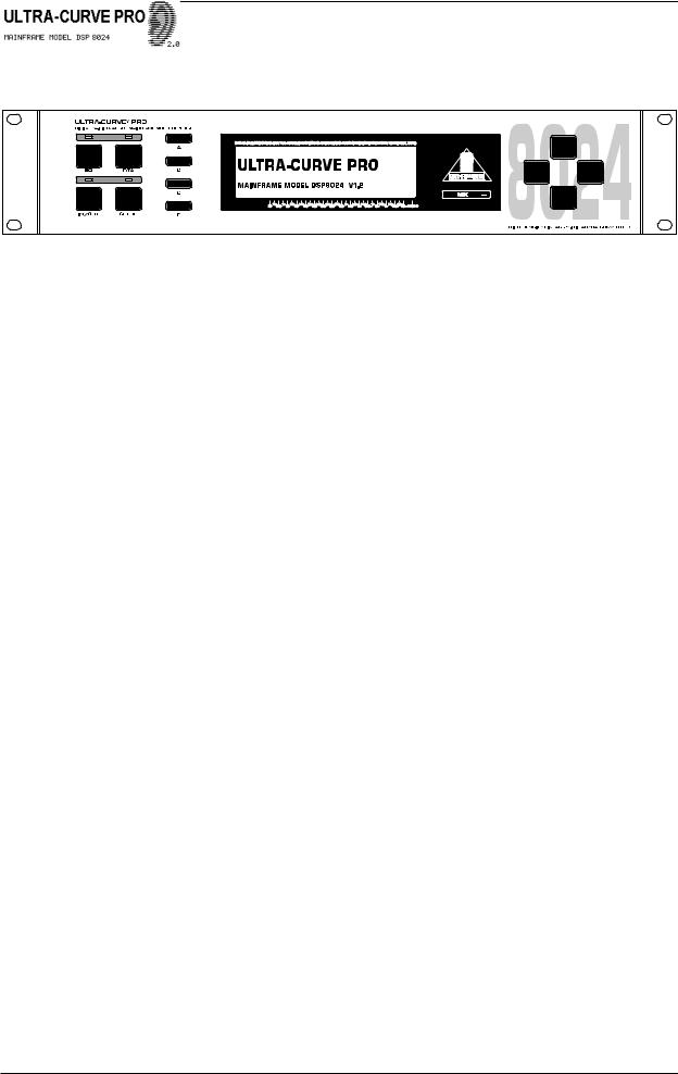
1.3 Control elements
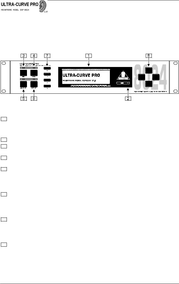
Fig. 1.1: The control surface of the ULTRA-CURVE PRO
1The heart of the front panel is the LED backlighted 240 x 64 active DISPLAY. The control of the ULTRA-CURVE PRO in centered around the central display. The user interface is for a large part graphical, complemented by four text based setup menus. The function of the softkeys is displayed right next to these keys, their function changes to accommodate different features.
2To the right of the display you will find the MIDI LED which registers incoming MIDI messages.
3The EQ key switches the ULTRA-CURVE PRO into equalizer mode. In this mode, the EQ, FEEDBACK DESTROYER, LIMITER and DELAY functions may be used.
4The RTA key switches the ULTRA-CURVE PRO into analyzer mode. This mode is solely concerned with measuring and signal generation, the sound will not be affected!
5IN/OUT key. The ULTRA-CURVE PRO can be switched into the signal path (LED is green) or switched out (bypass, LED dark). The LED flickering red indicates DSP overflow. This does not necessarily mean “clipping”. Flickering starts as soon as an internal overflow in one of the filters occurs, while input and output levels may be o.k. When this LED lights up often, reduce the input level or the ULTRA-CURVE PRO’s gain level.
6The SETUP key allows entry into the setup menus where all the basic adjustments of the device are to be found, such as the choice of input source, sample rate, password protection, MIDI configuration etc. Pressing once will open either the EQ setup or RTA setup, depending on the function of the unit. Holding the key down for two seconds or more will open the general setup windows consisting of a global setup and a MIDI setup window. Pressing the setup key here will toggle between both general setup windows.
7To the left of the display four SOFTKEYS, labelled A, B, C and D respectively, are to be found arranged vertically. Their functions can be defined by the user software and displayed to the immediate right of each key by the appropriate pictogram in the display. Each pictogram and its associated functions will be comprehensively explained in chapter 2. You will find function diagrams for both EQ and RTA mode as well as a list of all pictograms used on an extra sheet.
8To the right of the display the CURSOR KEYS are to be found. These are used:
1.to select individual filter frequencies, and the master fader in equalizer mode (horizontal)
2.to adjust the value of each selected frequency (vertical)
3.to position the measurement cursor in analyzer mode (horizontal)
4.in both operating modes, to choose the program position (vertical)
5.to select a field in the SETUP menu (horizontal and vertical)
1. INTRODUCTION |
7 |

ULTRA-CURVE PRO DSP8024
+In each case pressing on the opposite key while holding the key being used will accelerate the operation being carried out.
Fig. 1.2: The rear panel layout of the ULTRA-CURVE PRO
9This is the MAINS CONNECTOR/FUSE HOLDER/VOLTAGE SELECTOR. Before you connect the unit, please make sure that the displayed voltage corresponds to your mains supply. Please note that, depending on the mains voltage supplied to the unit, the correct fuse type and rate must be installed. In some units, the fuse holder can be inserted in two positions to switch between 220 to 240 V and 100 to 120 V. Please note that a higher fuse rating must be used when operating the unit outside of Europe with 115 V (see chapter 6 “INSTALLATION”).
10Please use the enclosed mains cable to connect the unit to the mains power supply.
11The MAINS SWITCH is to be found above the mains socket. The switch is situated on the rear panel to make the ULTRA-CURVE PRO tamper proof with unattended use. The unit will bypass on power failure but cannot be bypassed when a password is set.
12SERIAL NUMBER. Please take the time to have the warranty card filled out completely by your specialized dealer, and return it within 14 days after the date of purchase, so as to be entitled to benefit from our extended warranty. You may also use our online registration option available on the Internet at www.behringer.com.
13AES/EBU IN and AES/EBU OUT. These are the ULTRA-CURVE PRO’s digital input and output (optional). The analog output signal is also present at the (analog) outputs when the digital out is used. Both signals can be used in parallel.
14These are the ULTRA-CURVE PRO’s MIDI connectors (MIDI IN/OUT/THRU). Via these connectors total remote control is possible.
15ANALOG OUTPUTS. These are the ULTRA-CURVE PRO’s analog outputs. When the AES/EBU option is installed the analog output will still be present at these outputs, so that both analog and digital out can be used in parallel.
16These are the ULTRA-CURVE PRO’s ANALOG INPUTS.
17This is the MIC INPUT socket for the reference microphone.
2.OPERATION
The BEHRINGER ULTRA-CURVE PRO is a flexible, universally applicable sound processing and measurement device, whose operations may be divided into two basic areas; signal processor (equalizer, limiter) or real Time analyzer (RTA). For this reason, you always operate in either EQ or RTA mode. Simultaneous operation of both is not possible!
Upon switching on the ULTRA-CURVE PRO you will be presented either the main equalizer (EQ), or analyzer (RTA) window. By pressing the EQ or RTA key, the ULTRA-CURVE PRO will switch from RTAinto EQ mode and vice versa. When the ULTRA-CURVE PRO is switched from one mode to the other, the outputs will be briefly muted.
8 |
2. OPERATION |
ULTRA-CURVE PRO DSP8024
2.1 EQ mode
Fig. 2.1: Main EQ window of the ULTRA-CURVE PRO
The display shows a 31-band graphic equalizer, along with the main fader for overall level control—slightly separated on the right hand side. On the left are the pictograms for the softkeys, which are used to open the sub-menus.
2.1.1 Operating the graphic equalizer
The selected controller is illustrated highlighted in the display. The vertical cursor keys are used to adjust levels, the horizontal keys to select the controller to be adjusted. When you depress a cursor key, an information window appears showing the selected frequency, the level of boost or attenuation applied to each of the two channels, as well as the program number and program name:
Fig. 2.2: Graphic EQ information window
The information window disappears after four seconds if no further key has been pressed.
Depressing a key once will result in a parameter changing by the smallest applicable increment. The adjacent fader will be selected, or a level will be adjusted by 0.5 dB. Depressing and holding the cursor key results in a continuous change in the parameter. The rate of change remains constant. You can increase the rate of change by first depressing and holding the key used to change the relevant parameter, and then—still holding the first key—depress the one opposite.
2.1.2 The level meter
By pressing softkey A  you leave the main EQ window and access the menu to display levels.
Fig. 2.3: LEVEL METER display
You can use the level meter to control the input and output levels of the ULTRA-CURVE PRO. The bargraph display controls the effective RMS level (massive parts of the bars), and the peak level (checkered tips of the bars), both simultaneously. To save your eyes, the release time of the peak display is 20 dB/s. The maximum levels are memorized and numerically displayed.
2. OPERATION |
9 |

ULTRA-CURVE PRO DSP8024
When the limiter threshold is exceeded, the indication LIM will appear in the level meter display to indicate that the limiter is attenuating the output.
With softkey A  you leave the level meter, and return to the main EQ window.
With softkey B  you erase the maximum levels from the memory.
With softkey C  /
/ you switch the display from the ULTRA-CURVE PRO input and output.
With key D you can choose between three different tables of reference levels. The 0 dB point is indicated by a bold marker, while at the same time, the numerical display changes.  refers to the digital peak level. This level may not—under any circumstances—be exceeded! This will result in a very noticeable form of distortion, which occurs much faster, and sounds very much more unpleasant, than the familiar distortion associated with analog devices.
  refers to the operating level found in professional audio equipment (analog inputs and outputs of the ULTRA-CURVE PRO).
  refers to the operating level found in homerecording and domestic audio equipment, a typical example being tape recorders with RCA connectors. When setting the ULTRA-CURVE PRO internal level, or when using the optional AES/EBU interface, the peak level display of the DIG MAX scale is the only one to use. The +4 dBu and -10 dBV scales serve to monitor the analog inputs and outputs of the ULTRA-CURVE PRO.
Please note that the RMS level will usually be quoted in the technical specifications of analog devices for example, for the input sensitivity of power amplifiers. The effective level always lies below the peak level.
+The difference between them depends on the signal characteristics for a static sine wave, the effective level is about 3 dB below the peak level. For a dynamic signal the difference is in the region of 8 dB.
The DIG MAX level is, of course, related to the analog input and output levels, as 0 dB DIG MAX corresponds to the maximum output level of the ULTRA-CURVE PRO. The following example, using a sine wave at maximum amplitude, clearly illustrates the relationship between the various scales:
Scale |
|
Reading |
|
RMS |
|
PEAK |
|
|
|
||
DIGMAX |
-3 dB |
|
0 dB |
+4 dBu |
+6 dB |
|
+12 dB |
-10 dBV |
+21 dB |
|
+24 dB |
|
|
|
|
Maximum level: |
|
+16 dBu |
|
Tab. 2.1: Level meter scale correlation
As can be seen from the above table, the ULTRA-CURVE PROs maximum analog output level is +16 dBu, or +14 dBV.
The ULTRA-CURVE PROs analog inputs can handle signals of up to +21 dBu, but it is important to remember that, in case of such high input levels, the digital limiter may operate if the level in the equalizer is not appropriately lowered. Please refer to the operation of the digital limiter explained in section 2.1.6.
2.1.3 The FEEDBACK DESTROYER
By pressing softkey B  you leave the main EQ window and go into the FEEDBACK DESTROYER menu.
Fig. 2.4: FEEDBACK DESTROYER menu
The display will show the current settings for all six of the ULTRA-CURVE PRO parametric equalizers (selected frequency, bandwidth and degree of boost or attenuation). Additionally it will show whether the parameters are fixed (PAR), or are set for automatic search, to function as the FEEDBACK DESTROYER (AUT or SGL). Auto
10 |
2. OPERATION |
ULTRA-CURVE PRO DSP8024
search means that the audio signal is continuously examined for signs of feedback. If feedback is detected, the ULTRA-CURVE PRO will assign an appropriate filter to the relevant frequency and apply narrow band attenuation, also known as a “notch filter”. The parameters which have been used will be continuously displayed.
The next feedback will be dealt with by the next available filter. When all the filters have been used, and feedback still occurs, the filter used for the first, or oldest frequency will be released to deal with the newest one. If feedback occurs very close to a frequency already being treated, or reappears at a frequency to which a filter has already been applied, the filter already in use will have its parameters changed to deal with the new problem—i. e. the bandwidth will be widened, or the attenuation increased.
In single shot mode (SGL) the filter will not release a setting which has been achieved, this is particularly useful with problems at fixed frequencies like turntable resonances and fixed microphone and monitor positions. If feedback is detected the filter will deal with that frequency and the status of that filter will change to locked (LCK). It will only widen its bandwidth or increase the attenuation but it will not release that frequency to deal with a new feedback frequency. Please note the application example in section 3.2.
2.1.4 Delay
By pressing softkey C  /
/ the built in signal delay can be switched on or off. The display shows the current status:
1. = switched off
2. = switched on, signal will be delayed by the preset numerical value.
You can set the delay time in the EQ SETUP menu (see chapter 2.1.6). Among its many uses, it can be used to compensate for time path differences between two sets of loudspeakers set at different distances to the listener. See chapter 3.4 for an application example.
2.1.5 Equalizer editing
By pressing softkey D  or by using a cursor key, the function of the softkeys is changed, and this is highlighted by a new set of pictograms. With these, you can access either further sub-menus with their own functions, or carry out important switching functions. We remind you to the function diagrams on the extra sheet. They give you an overview of the way all the menus and sub menus are inserted into one other, in EQ and RTA mode respectively.
Fig. 2.5: EQ EDITING display
You can now enter with softkey A  the program administration to store, load and name settings with softkey B
  the tools menu, with softkey C
  /
/ the channel switching (stereolink on),
  /
/ the channel switching (stereolink off) and with softkey D
  /
/ the comparison functions.
Program administration
A program contains the settings for the graphic equalizer, the parametric filters and the delay. Softkey A  allows access to further sub menus which are used to organize the program administration:
a) Loading programs
Softkey A  : This shows, in the equalizer display, the same information window as shown when operating a fader. However, in contrast to normal equalizer operation, you cannot change the level with the cursor key, instead you can select a new program. You can confirm this with
  or cancel it with
  . In both cases you are then returned back to the EDIT menu.
Using softkey D  you can reset all the current ULTRA-CURVE PRO settings—the graphic equalizer, the parametric filters (also in feedback destroyer mode) and the delay—to zero. You will first be presented with the
2. OPERATION |
11 |
 Loading...