


User Manual
VLINX
VESP211
SERIAL SERVER
Version 1.0

Vlinx Serial Servers
Model VESP211
Documentation Number: VESP211-0712m
This product designed and manufactured in Ottawa, Illinois USA using domestic and imported parts by
International Headquarters:
707 Dayton Road - P.O. Box 1040 - Ottawa, IL 61350 USA
Phone (815) 433-5100 - General Fax (815) 433-5105
Website: www.bb-elec.com
European Headquarters:
B&B Electronics
Westlink Commercial Park - Oranmore, Co. Galway, Ireland
Phone +353 91-792444 - Fax +353 91-792445
Website: www.bb-europe.com
B&B Electronics Mfg. Co. Inc – November 2011
©2010 B&B Electronics Mfg Co Inc No part of this publication may be reproduced or transmitted in any form or by any means, electronic or mechanical, including photography, recording, or any information storage and retrieval system without written consent. Information in this manual is subject to change without notice, and does not represent a commitment on the part B&B Electronics Mfg Co Inc.
B&B Electronics Mfg Co Inc shall not be liable for incidental or consequential damages resulting from the furnishing, performance, or use of this manual.
All brand names used in this manual are the registered trademarks of their respective owners. The use of trademarks or other designations in this publication is for reference purposes only and does not constitute an endorsement by the trademark holder.

Table of Contents |
|
|
Introduction ........................................................................................................... |
|
7 |
About VESP211 Serial Servers............................................................................. |
|
7 |
VESP211 Serial Server Model Numbering.............................................................. |
|
8 |
VESP211 Features ............................................................................................. |
|
8 |
Vlinx Manager Configuration Software .................................................................. |
|
8 |
VESP211 Hardware................................................................................................. |
|
9 |
Package Checklist .............................................................................................. |
|
9 |
VESP211 Serial Server Enclosures and Mounting ................................................... |
|
9 |
LED Indicators ................................................................................................. |
|
10 |
Ready LED ........................................................................................... |
|
10 |
Ethernet LED........................................................................................ |
|
10 |
Serial LED............................................................................................ |
|
10 |
Reset Switch .................................................................................................... |
|
11 |
Using the Reset Switch to Initiate a Hardware Reset ................................. |
11 |
|
Using the Reset Switch to Enter Console Mode ......................................... |
11 |
|
Using the Reset Switch to exit Console Mode............................................ |
12 |
|
Using the Reset Switch to Reload Factory Default Settings ......................... |
12 |
|
Ethernet Connector........................................................................................... |
|
12 |
Serial Port Connectors....................................................................................... |
|
12 |
Power Connector .............................................................................................. |
|
13 |
Mounting Hardware........................................................................................... |
|
13 |
Initial Setup and Connections............................................................................... |
|
15 |
Connecting the Power Supply ............................................................................. |
|
15 |
Connecting VESP211 Serial Servers to Serial Devices ............................................ |
15 |
|
RS-232................................................................................................ |
|
15 |
RS-422................................................................................................ |
|
15 |
RS-485................................................................................................ |
|
16 |
Connecting VESP211 Serial Servers to a Network ................................................. |
|
16 |
Ethernet Connection (10BaseT/100BaseTX) ............................................. |
|
16 |
VESP211 Serial Server Configuration Connections................................................. |
|
17 |
Configuring via the Network using Vlinx Manager...................................... |
17 |
|
Configuring via the network using a Browser ............................................ |
17 |
|
Configuring via the Serial Port using Vlinx Manager (Console Mode) |
............18 |
|
VESP211 Serial Server Operational Connections ................................................... |
|
18 |
Page 3 of 66 |
Manual Documentation Number: VESP211-5011m |
|
|
|
www.bb-elec.com/ |
|
www.bb-europe.com/ |
|
Installing and Starting Vlinx Manager .................................................................. |
20 |
Discovering Serial Servers ................................................................................. |
20 |
Configuring the Serial Server ............................................................................... |
22 |
Overview of the Vlinx Manager ........................................................................... |
22 |
Icons................................................................................................... |
23 |
Serial Server Information Table .............................................................. |
23 |
Configuration Pane................................................................................ |
24 |
Logging In ....................................................................................................... |
24 |
Navigating the Configuration Pages..................................................................... |
25 |
Setting up the Serial Server Name and Password ................................................. |
25 |
Changing the serial server’s name: ......................................................... |
26 |
Changing the password: ........................................................................ |
26 |
Setting up IP Addressing ................................................................................... |
26 |
Setting up Dynamic IP Addressing .......................................................... |
27 |
Setting up Static IP Addressing .............................................................. |
27 |
Setting up Serial Ports ...................................................................................... |
27 |
Setting up Port Network Parameters ................................................................... |
28 |
TCP Configuration ................................................................................. |
29 |
UDP Configuration ................................................................................ |
30 |
Setting up Virtual COM (VCOM) Operation ............................................... |
32 |
Setting up Paired Mode Operation ........................................................... |
33 |
Setting up Advanced Network Settings ................................................................ |
35 |
Configuring when connections will be forced closed ................................... |
36 |
Configuring when data packets are sent .................................................. |
37 |
Saving/Restoring the Configuration Settings ........................................................ |
40 |
Adding Virtual COM Ports................................................................................... |
40 |
Removing Virtual COM Ports ............................................................................. |
41 |
Upgrading the Serial Server Firmware.................................................................. |
44 |
Downloading Firmware Files............................................................................... |
44 |
To download the latest firmware files from an FTP site on the Internet ........ |
45 |
To download the latest firmware files from a file ....................................... |
45 |
Uploading the Firmware to the Serial Server ........................................................ |
45 |
Diagnostics........................................................................................................... |
46 |
Testing a Serial Server Connection ..................................................................... |
46 |
Testing a Virtual COM Port ................................................................................. |
47 |
Page 4 of 66 |
Manual Documentation Number: VESP211-5011m |
|||
|
|
|
|
|
|
|
|
www.bb-elec.com/ |
|
|
|
|
|
|
|
|
www.bb-europe.com/ |
||
Description of Serial Server Properties................................................................. |
49 |
Appendix .............................................................................................................. |
59 |
Appendix A: Default Server Settings ................................................................... |
59 |
Appendix B: Product Specifications ..................................................................... |
60 |
General Specifications ........................................................................... |
60 |
Controls, Indicators and Connector Specifications ..................................... |
61 |
Serial Interface Specifications ................................................................ |
61 |
Network Specifications .......................................................................... |
62 |
TCP/UDP Ports Table ............................................................................. |
62 |
Appendix C: Dimensional Diagram ...................................................................... |
64 |
Appendix D: Connector Pinouts .......................................................................... |
65 |
DB-9M Connnector................................................................................ |
65 |
Terminal Block ..................................................................................... |
65 |
Standard Ethernet Cable RJ-45 Pin-out.................................................... |
66 |
Page 5 of 66 |
Manual Documentation Number: VESP211-5011m |
|||
|
|
|
|
|
|
|
|
www.bb-elec.com/ |
|
|
|
|
|
|
|
|
www.bb-europe.com/ |
||
Section 1 - Introduction |
Vlinx VESR4x4 Serial Server |
SECTION 1
Introduction
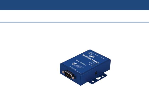
Thank you for purchasing a VESP211 Serial Server product! This product has been manufactured to the highest standards of quality and performance to ensure your complete satisfaction.
Figure 1. A VESP211 Serial Server
About VESP211 Serial Servers
VESP211 Serial Servers connect serial devices (RS-232, RS-422 or RS-485) to Ethernet networks, allowing the serial device to become a node on the network. The serial port can be accessed over a LAN/WAN using Direct IP Mode, Virtual COM Port, or Paired Mode connections. VESP211 Serial Servers support 10BaseT or 100BaseTX copper networks. The product is built for use in industrial environments, and features a heavy duty metal enclosure that is panel (standard) or DIN rail mountable (with optional adapter). The product includes a DC power supply with a 2.1mm barrel connector.
Page 7 of 66 |
Manual Documentation Number: VESP211-5011m |
|||
|
|
|
|
|
|
|
|
www.bb-elec.com/ |
|
|
|
|
|
|
|
|
www.bb-europe.com/ |
||
Section 1 - Introduction |
Vlinx VESR4x4 Serial Server |
VESP211 Serial Server Model Numbering
The VESP211 Serial Server family of products includes three models:
VESP211-232, which uses a DB-9M connector and supports the RS-232 serial interface
VESP211-485, which uses a pluggable, five-position terminal strip and supports the RS-485 serial interface
VESP211 which uses a DB-9M connector and supports the RS-232, RS422 and RS-485 serial interfaces
All models incorporate one serial connection and one Ethernet connection.
VESP211 Features
Multi-interface serial port (VESP211)
DB-9M serial port connector (VESP211 and VESP211-232)
Five-position pluggable terminal strip (VESP211-485)
Configuration can be done via network or direct serial connection
Rugged panel mountable metal case
Accepts 12 VDC power (power adapter included)
10/100 Mbps Ethernet with Auto Selection
LAN and WAN Communications
TCP Client or Server, or UDP operation - configurable
Virtual COM port and Paired Mode capabilities
Firmware Upload over the network for future revisions/upgrades
Software Support - XP (32/64 bit), 2003 Server (32/64 bit), Vista (32/64 bit), 2008 Server (32/64 bit), Windows 7 (32/64 bit)
Configuration of Ethernet and serial port settings using Vlinx Manager software
Vlinx Manager Configuration Software
Vlinx Manager configuration software enables you to find connected serial servers, configure them, upgrade serial server firmware, and save/load configuration files. It features a graphical user interface (GUI) that is convenient and easy to use. The software also makes it easy to add and remove virtual COM ports on your computer.
Page 8 of 66 |
Manual Documentation Number: VESP211-5011m |
|||
|
|
|
|
|
|
|
|
www.bb-elec.com/ |
|
|
|
|
|
|
|
|
www.bb-europe.com/ |
||
Section 2 - VESP211 Hardware |
Vlinx VESR4x4 Serial Server |
SECTION 2
VESP211 Hardware
VESP211 Serial Servers are enclosed in a rugged panel mountable enclosure and feature:
LED indicators
Power, Ethernet and serial connectors
A recessed Reset (mode) switch.
Package Checklist
VESP211 Serial Servers are shipped with the following items included:
VESP211 Serial Server Module
Quick Start Guide
CD with User Manual, Quick Start Guide
DC Power Supply
VESP211 Serial Server Enclosures and Mounting
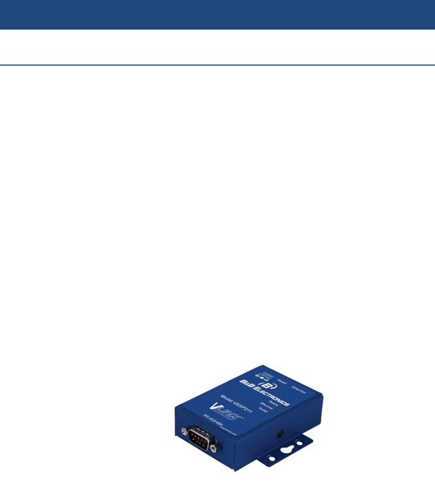
All VESP211 models are built into similar enclosures. Modules are panel mountable.
Figure 2. Front View of the VESP211 Serial Server
Page 9 of 66 |
Manual Documentation Number: VESP211-5011m |
|||
|
|
|
|
|
|
|
|
www.bb-elec.com/ |
|
|
|
|
|
|
|
|
www.bb-europe.com/ |
||

Section 2 - VESP211 Hardware |
Vlinx VESR4x4 Serial Server |
LED Indicators
VESP211s have three LED indicators: a Ready LED, an Ethernet LED, and a
Serial LED.
Figure 3. Front Panel of the VESP211
Ready LED
The Ready LED (green) blinks once per second if the system is operating correctly. If the LED is off, it indicates the system is not operating correctly (or that it is in Console Mode).
Ethernet LED
The Ethernet LED illuminates if the Ethernet port is connected and blinks when data is transmitted or received.
Serial LED
The serial port has an associated LED. The Serial Port LED blinks (green) when data is being transmitted or received on the serial port. When the LED is On, it indicates that the serial port is open.
Page 10 of 66 |
Manual Documentation Number: VESP211-5011m |
|||
|
|
|
|
|
|
|
|
www.bb-elec.com/ |
|
|
|
|
|
|
|
|
www.bb-europe.com/ |
||
Section 2 - VESP211 Hardware |
Vlinx VESR4x4 Serial Server |
|
Note: |
LEDs on the serial server are also used to indicate various Reset modes, as described in the |
|
|
following section. |
|
Reset Switch
A recessed momentary Reset switch is located on the side of the enclosure. To activate the switch, insert a small plastic tool through the hole in the enclosure and press lightly.
Figure 4. Ethernet Connector, Reset Switch (recessed) and Power Connector
The Reset switch can be used to:
Initiate a Hardware Reset
Enter Console Mode
Reload factory defaults
Using the Reset Switch to Initiate a Hardware Reset
Hold the Reset switch in for 0 to 2 seconds. The Ready LED stops blinking while the switch is being held in. The Serial LED illuminates while the switch is being held in. Release the switch in less than two seconds or the serial server will enter Console Mode.
Using the Reset Switch to Enter Console Mode
Hold the Reset switch for between two and ten seconds. The Ready LED stops blinking while the switch is being held in. The Serial LED illuminates for the first two seconds; then Serial LED goes out and the Ready LED illuminates. Release the switch in less than 10 seconds or the serial server will reset to factory default settings.
Page 11 of 66 |
Manual Documentation Number: VESP211-5011m |
|||
|
|
|
|
|
|
|
|
www.bb-elec.com/ |
|
|
|
|
|
|
|
|
www.bb-europe.com/ |
||

Section 2 - VESP211 Hardware |
Vlinx VESR4x4 Serial Server |
Using the Reset Switch to exit Console Mode
Press and hold the Reset switch for two seconds, or remove power from the serial server, wait a few seconds, and turn the power on again. The LEDs go back to their normal states when the device resumes normal operation.
Using the Reset Switch to Reload Factory Default Settings
Hold the Reset switch for more than ten seconds. The Serial LED illuminates for the first two seconds; then the Ready LED illuminates. After 10 seconds, both the Serial and Ready LEDs illuminate. Release the switch after more than 10 seconds. The serial server will reset to factory default settings.
Ethernet Connector
The Ethernet connection uses an RJ45 receptacle. The serial server is connected to a standard Ethernet network drop using a straight-through RJ45 (male) Ethernet cable.
Note: Refer to Appendix D for connection pin-outs.
Serial Port Connectors
VESP211 Serial Servers feature two serial port connector configurations, depending on the model:
VESP211 and VESP211-232 use DB-9M connectors for RS-232, RS-422 and RS-485 connections.
Figure 5. DB-9M Serial Port Connector
Page 12 of 66 |
Manual Documentation Number: VESP211-5011m |
|||
|
|
|
|
|
|
|
|
www.bb-elec.com/ |
|
|
|
|
|
|
|
|
www.bb-europe.com/ |
||

Section 2 - VESP211 Hardware |
Vlinx VESR4x4 Serial Server |
VESP211-485 serial servers use five-position removable terminal blocks for RS-422 and RS-485 connections.
Figure 6. Five-Position Pluggable Terminal Blocks
Note: Refer to Appendix D for connection pin-outs.
Power Connector
VESP211 serial servers use a barrel jack connector for power. The connector accepts a 2.1 millimeter plug and requires 12 VDC at 2.5 W maximum.
Figure 7. Ethernet Connector, Reset Switch (recessed) and Power Connector
Mounting Hardware
VESP211 Serial Server modules can be panel mounted using the built-in mounting brackets.
Page 13 of 66 |
Manual Documentation Number: VESP211-5011m |
|||
|
|
|
|
|
|
|
|
www.bb-elec.com/ |
|
|
|
|
|
|
|
|
www.bb-europe.com/ |
||

Section 2 - VESP211 Hardware |
Vlinx VESR4x4 Serial Server |
Figure 8. VESP211 Enclosure with Panel Mount Bracket
An optional DIN rail mount adapter is available from B&B Electronics.
Page 14 of 66 |
Manual Documentation Number: VESP211-5011m |
|||
|
|
|
|
|
|
|
|
www.bb-elec.com/ |
|
|
|
|
|
|
|
|
www.bb-europe.com/ |
||

Section 3 - Initial Setup and Connections |
Vlinx VESR4x4 Serial Server |
SECTION 3
Initial Setup and Connections
This section describes how to setup and connect VESP211 Serial Servers.
Note: In this section devices to be connected to the serial server’s serial connection are simply referred to as the “serial device”.
Connecting the Power Supply
Connect a DC power supply by plugging a 12 VDC power source into the barrel jack on the top of the serial server. The center connection must be positive (+). (Polarity of the connection is indicated on the label on the front of the serial server.) The power supply must be capable of supplying 2.5 watts maximum.
Connecting VESP211 Serial Servers to Serial Devices
VESP211 Serial Servers can be connected to serial devices using RS-232, RS422, RS-485 2-wire and RS-485 4-wire.
RS-232
The RS-232 interface supports seven RS-232 signal lines (TD, RD, DTR, DSR, RTS, CTS, DCD) plus Signal Ground.
Signals are single ended and referenced to Ground. Default communications parameters are 9600, 8, N, 1 and no flow control implemented.
Note: |
The VESP211 is configured as a DTE. If it is connected to a serial device configured as a DTE, use |
|
a null modem (cross-over) cable. If the serial device is a DCE, use a straight-through cable. |
RS-422
The RS-422 interface supports two signal pairs: TDA (-), TDB (+), RDA (-), RDB (+) and GND. The data lines are differential pairs (A & B) in which the B line is positive relative to the A line in the idle (mark) state. Ground provides a common mode reference.
Page 15 of 66 |
Manual Documentation Number: VESP211-5011m |
|||
|
|
|
|
|
|
|
|
www.bb-elec.com/ |
|
|
|
|
|
|
|
|
www.bb-europe.com/ |
||
Section 3 - Initial Setup and Connections |
Vlinx VESR4x4 Serial Server |
RS-485
The RS-485 interface supports 2-wire or 4-wire operation.
When configured for 4-wire operation the connection supports two signal pairs: TDA (-), TDB (+), RDA (-), RDB (+) and GND. This makes full-duplex operation possible. The data lines are differential pairs (A & B) in which the B line is positive relative to the A line in the idle (mark) state. Ground provides a common mode reference.
When configured for 2-wire operation the connection supports one signal pair: Data A (-) and Data B (+) signal channels using half-duplex operation. The data lines are differential with the Data B line positive relative to Data A in the idle (mark) state. Ground provides a common mode reference.
Note: |
Refer to Appendix D for connector pinout information. |
Figure 9. VESP211 Connections
Connecting VESP211 Serial Servers to a Network
Ethernet Connection (10BaseT/100BaseTX)
The Ethernet connection uses a standard RJ45 connector. A standard network cable is connected from the serial server to a network drop. PCs configuring and/or communicating with the serial server are also connected to the network.
Page 16 of 66 |
Manual Documentation Number: VESP211-5011m |
|||
|
|
|
|
|
|
|
|
www.bb-elec.com/ |
|
|
|
|
|
|
|
|
www.bb-europe.com/ |
||

Section 3 - Initial Setup and Connections |
Vlinx VESR4x4 Serial Server |
VESP211 Serial Server Configuration Connections
VESP211 Serial Servers can be configured using several methods:
Via the network using Vlinx Manager software
Via the network using a web browser
Via the serial port using Vlinx Manager software (Console Mode)
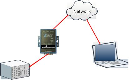
Configuring via the Network using Vlinx Manager
|
VESP211 Serial Servers can be configured over the network using Vlinx |
|
Manager software running on a networked PC. Vlinx Manager includes a |
|
discovery function that makes it possible to detect the serial server on the |
|
network whether you know its IP address or not. Once the serial server has |
|
been detected, the Manager can be used to configure its settings. |
Note: |
For more information on how to use Vlinx Manager to configure your serial server, refer to Section 4: |
|
Configuring the Serial Server |
Figure 10. Network Setup
Configuring via the network using a Browser
|
VESP211 Serial Servers can also be configured over the network using a |
|||
|
standard internet browser such as Internet Explorer or Firefox running on a |
|||
|
networked PC. To do so you must know the IP address of the serial server. |
|||
|
Your serial server comes from the factory pre-configured to receive an IP |
|||
|
address from a DHCP Server. If DHCP assignment is not available it will |
|||
|
default to 169.254.102.39 |
|||
Page 17 of 66 |
Manual Documentation Number: VESP211-5011m |
|||
|
|
|
|
|
|
|
|
www.bb-elec.com/ |
|
|
|
|
|
|
|
|
www.bb-europe.com/ |
||
Section 3 - Initial Setup and Connections |
Vlinx VESR4x4 Serial Server |
|
Note: |
For more information on how to use Vlinx Manager to configure your serial server, refer to Section 4: |
|
|
Configuring the Serial Server |
|
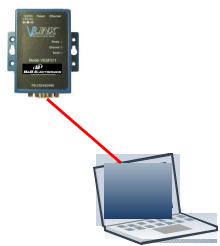
Configuring via the Serial Port using Vlinx Manager (Console Mode)
Your serial server can be configured via the serial port using Vlinx Manager. To use this feature the serial port must be connected to the serial port of a PC (using a null modem cable).
|
Figure 11. Console Mode Setup |
|
To configure the serial server it must be put into Console Mode, using the |
|
Reset switch. |
Note: |
Refer to Section 2 for information on how to use the Reset switch to enter Console Mode. |
VESP211 Serial Server Operational Connections
VESP211 Serial Servers can operate in Direct IP, Virtual COM Port and Paired Modes.
In Direct IP Mode applications using TCP/IP or UDP/IP socket programs can communicate with the COM ports on the serial server. In this type of application the serial server is configured as a TCP or UDP server. The socket program running on the PC establishes a communication connection with the serial server. The data is sent directly to and from the serial port on the server.
Page 18 of 66 |
Manual Documentation Number: VESP211-5011m |
|||
|
|
|
|
|
|
|
|
www.bb-elec.com/ |
|
|
|
|
|
|
|
|
www.bb-europe.com/ |
||

Section 3 - Initial Setup and Connections |
Vlinx VESR4x4 Serial Server |
Figure 12. Direct IP and Virtual COM Port Connection
In Virtual COM Port Mode a PC can communicate across the network to the serial server as if the serial ports on the serial server are the PC’s serial ports.
When a virtual COM port is configured on the PC (using Vlinx Manager) a new COM port appears in the Device Manager. Windows programs using standard Windows API calls are able to interface to virtual COM ports. When a program on the PC opens the new COM port, it communicates directly with the remote serial device connected to the serial server.
In Paired Mode, two serial servers (connected to serial devices via their serial ports) are connected to the network. The serial devices communicate directly, transferring data between devices as a point-to-point serial connection. Paired Mode is set up as shown in the following diagram and configured using Vlinx Manager software or web interface.
Figure 13. Paired Mode Setup
Page 19 of 66 |
Manual Documentation Number: VESP211-5011m |
|||
|
|
|
|
|
|
|
|
www.bb-elec.com/ |
|
|
|
|
|
|
|
|
www.bb-europe.com/ |
||

Section 3 - Initial Setup and Connections |
Vlinx VESR4x4 Serial Server |
Installing and Starting Vlinx Manager
Vlinx Manager is a Windows-based application used to configure serial servers. Install it on your PC from the included CD. Installation should launch automatically when the CD is placed in the CD-ROM drive. If it does not automatically launch, click Start on the Windows Desktop and, at the Run command, type the drive letter and Vlinx Manager.exe. Follow the prompts to install the software.
Once the program is installed, go to the Start > Programs menu and run the program.
The Vlinx Manager Discovery window appears.
Figure 14. Discovery Window
Discovering Serial Servers
|
If you are configuring the serial server via the network, select Network; if you |
|||
|
are configuring it via the serial port, select Serial Port. |
|||
|
If you already know the IP address of the serial server, click The device is at |
|||
|
this IP address; if not, leave I don’t know the IP address of the device |
|||
|
selected. |
|||
|
Click Connect. The Progress bar provides information to indicate whether |
|||
|
serial servers are detected. |
|||
|
The text in the Progress box appears in various colors, depending on the |
|||
|
message type. |
|||
Page 20 of 66 |
Manual Documentation Number: VESP211-5011m |
|||
|
|
|
|
|
|
|
|
www.bb-elec.com/ |
|
|
|
|
|
|
|
|
www.bb-europe.com/ |
||
 Loading...