


SPECTRE Router
USER MANUAL
SPECTRE_User_Manual_2912m
www.bb-elec.com
www.bb-europe.com

B&B Electronics, Inc. |
SPECTRE User Manual |
|
|
International Headquarters
B&B Electronics Mfg. Co. Inc.
707 Dayton Road
Ottawa, IL 61350 USA
Phone (815) 433-5100 -- General Fax (815) 433-5105
Website: www.bb-elec.com
European Headquarters
B&B Electronics Ltd.
Westlink Commercial Park
Oranmore, Co. Galway, Ireland
Phone +353 91-792444 -- Fax +353 91-792445
Website: www.bb-europe.com
Doc: 710-10001-01 Rev 1.0 – October 2012
2012 B&B Electronics Mfg. Co. Inc. No part of this publication may be reproduced or transmitted in any form or by any means, electronic or mechanical, including photography, recording, or any information storage and retrieval system without written consent. Information in this manual is subject to change without notice, and does not represent a commitment on the part of B&B Electronics Mfg. Co. Inc.
B&B Electronics Mfg. Co. Inc. shall not be liable for incidental or consequential damages resulting from the furnishing, performance, or use of this manual.
All brand names used in this manual are the registered trademarks of their respective owners. The use of trademarks or other designations in this publication is for reference purposes only and does not constitute an endorsement by the trademark holder.
2
SPECTRE_User_Manual_2912m www.bb-elec.com www.bb-europe.com

B&B Electronics, Inc. |
SPECTRE User Manual |
Used symbols
Danger – Information regarding user safety or potential damage to the router.
Attention – Problems that can arise in specific situations.
Useful tips or information of special interest.
GPL license
Source codes under GPL license are available free of charge by sending an email to support@bbelec.com.
Router version
The properties and settings associated with the cellular network connection are not available in noncellular SPECTRE RT routers.
PPPoE configuration is only available on SPECTRE RT routers. It is used to set the PPPoE connection over Ethernet.
Declared quality system
ISO 9001
B&B Electronics
3
SPECTRE_User_Manual_2912m www.bb-elec.com www.bb-europe.com

B&B Electronics, Inc. SPECTRE User Manual
Contents
1. |
Safety Instructions |
7 |
||
|
1.1 |
Compliance |
7 |
|
|
1.2 |
Product disposal instructions |
7 |
|
2. |
Router Description |
8 |
||
|
2.1 |
Description |
8 |
|
|
2.2 |
Examples of possible applications: |
8 |
|
|
2.3 |
Package Contents |
9 |
|
|
2.4 |
Model Numbers |
10 |
|
|
2.5 |
Dimensions |
11 |
|
3. |
Mounting Recommendations |
12 |
||
4. |
User Interfaces |
15 |
||
|
4.1 |
Connectors |
15 |
|
|
4.2 |
Status Indicators |
16 |
|
|
4.2.1 |
Auxiliary Port Status Indicators |
17 |
|
|
4.2.1.1Ethernet Ports |
17 |
||
|
4.2.1.2RS-232 Ports |
17 |
||
|
4.2.1.3I/O Ports |
17 |
||
|
4.2.1.4RS-485/422 Ports |
17 |
||
|
4.3 |
Power Connector |
18 |
|
|
4.4 |
Antenna Connector |
19 |
|
|
4.5 |
SIM Card Reader |
20 |
|
|
4.6 |
Ethernet Port |
21 |
|
|
4.7 |
Auxiliary Port Connectors |
22 |
|
|
4.7.1 |
RS-232 Ports |
22 |
|
|
4.7.2 |
RS-485/422 Ports |
24 |
|
|
4.7.3 |
I/O Port |
29 |
|
|
4.7.3.1Analog Inputs |
29 |
||
|
4.7.3.2Binary Input |
29 |
||
|
4.7.3.3Counter Inputs |
29 |
||
|
4.7.3.4Binary Output |
29 |
||
|
4.7.3.5Selecting the Binary Input Current |
30 |
||
|
4.7.3.6Input/Output Connector |
31 |
||
|
4.8 |
USB Port |
38 |
|
|
4.9 |
I/O Port |
40 |
|
5. Resetting or Rebooting the Router |
42 |
|||
6. |
Initial Setup |
43 |
||
|
6.1 |
Starting the Router |
44 |
|
|
6.2 |
Configuring the Router |
44 |
|
|
6.2.1 Configuration using a Web browser |
44 |
||
|
6.2.2 |
Configuration over Telnet |
44 |
|
|
6.3 |
Technical Parameters |
45 |
|
7. |
Troubleshooting |
47 |
||
|
7.1 |
FAQ |
47 |
|
8. |
Customer Support |
49 |
||
4
SPECTRE_User_Manual_2912m www.bb-elec.com www.bb-europe.com

B&B Electronics, Inc. |
SPECTRE User Manual |
Figure List |
|
Fig. 1: Contents of package.................................................................................................................. |
9 |
Fig. 2: Basic dimensions, metal box ................................................................................................. |
11 |
Fig. 3: Recommended clearance around antennas ......................................................................... |
12 |
Fig. 4: Cable routing............................................................................................................................ |
13 |
Fig. 5: Space in front connectors ...................................................................................................... |
14 |
Fig. 6: Front panel SPECTRE 3G ....................................................................................................... |
15 |
Fig. 7: Power connector...................................................................................................................... |
18 |
Fig. 8: Connection of power supply connector ................................................................................ |
18 |
Fig. 9: Connection of power supply .................................................................................................. |
18 |
Fig. 10: External antenna .................................................................................................................... |
19 |
Fig. 11: Connecting the antenna ........................................................................................................ |
19 |
Fig. 12: Ejected SIM card holder ........................................................................................................ |
20 |
Fig. 13: Ethernet connector ................................................................................................................ |
21 |
Fig. 14: Ethernet Cable Connection................................................................................................... |
21 |
Fig. 15: Example of router connection .............................................................................................. |
22 |
Fig. 16: RS232 port connector............................................................................................................ |
23 |
Fig. 17: Meter connection to router ................................................................................................... |
23 |
Fig. 18: PC connection to router ........................................................................................................ |
24 |
Fig. 19: RS-232 equipment connection to router ............................................................................. |
24 |
Fig. 20: Jumper Position for external supply ................................................................................... |
25 |
Fig. 21: Jumper Position for RS-485.................................................................................................. |
25 |
Fig. 22: Jumper Position for internal supply .................................................................................... |
25 |
Fig. 23: Jumper Position for RS-422.................................................................................................. |
25 |
Fig. 24: RS485/422 connector............................................................................................................. |
26 |
Fig. 25: Connection to the router with data cable length less than 10 m ...................................... |
26 |
Fig. 26: Connection to the router with data cable length more than 10 m .................................... |
27 |
Fig. 27: Connection to the router with data cable length less than 10 m ...................................... |
28 |
Fig. 28: Connection to the router with data cable length more than 10 m .................................... |
28 |
Fig. 29: Connection of the I/O Port circuitry ..................................................................................... |
32 |
Fig. 30: USB connector ....................................................................................................................... |
38 |
Fig. 31: Connecting a PLC to the router............................................................................................ |
39 |
Fig. 32: Connecting USB memory stick to the router ...................................................................... |
39 |
Fig. 33: I/O connection ........................................................................................................................ |
40 |
Fig. 34: Connection I/O cable ............................................................................................................. |
40 |
Fig. 35: Connection of binary input and output of router ............................................................... |
41 |
Fig. 36: Router reset............................................................................................................................ |
42 |
Fig. 37: Router connections ............................................................................................................... |
43 |
5
SPECTRE_User_Manual_2912m www.bb-elec.com www.bb-europe.com

B&B Electronics, Inc. |
SPECTRE User Manual |
Table list |
|
Table 1: Auxiliary port possibilities ................................................................................................... |
10 |
Table 2: Model numbers ..................................................................................................................... |
10 |
Table 3: Front panel description ........................................................................................................ |
15 |
Table 4: Router status indication....................................................................................................... |
16 |
Table 5: Ethernet LED status indication ........................................................................................... |
17 |
Table 6: RS-232 LED status indication.............................................................................................. |
17 |
Table 7: I/O Port LED status indication ............................................................................................. |
17 |
Table 8: RS-485/422 LED status indication....................................................................................... |
17 |
Table 9: Connection of power connector.......................................................................................... |
18 |
Table 10: Ethernet connector ............................................................................................................. |
21 |
Table 11: RS232 connector Pinout .................................................................................................... |
23 |
Table 12: Connector Pinout in RS-485 Mode.................................................................................... |
26 |
Table 13: Connector Pinout in RS-422 Mode.................................................................................... |
27 |
Table 14: Input/Output Connector Pinout ......................................................................................... |
31 |
Table 15: MODBUS Input/Output Address space ............................................................................ |
37 |
Table 16: Connection of USB connector........................................................................................... |
38 |
Table 17: I/O port Connection ............................................................................................................ |
40 |
Table 18: Ways to reset or restart the router.................................................................................... |
42 |
Table 19: Specifications...................................................................................................................... |
45 |
Table 20: Cellular Module Specifications.......................................................................................... |
45 |
Table 21: Processor Specifications................................................................................................... |
46 |
Table 22: I/O Port Specifications ....................................................................................................... |
46 |
6
SPECTRE_User_Manual_2912m www.bb-elec.com www.bb-europe.com

B&B Electronics, Inc. |
SPECTRE User Manual |
1. Safety Instructions
1.1Compliance
Please observe the following instructions:
The router must be used in compliance with all applicable international and national laws and in compliance with any special restrictions regulating the use of the router in prescribed applications and environments.
To prevent possible injury and damage to appliances and to ensure compliance with all relevant provisions, use only the original accessories. Unauthorized modifications or the use of unapproved accessories may result in damage to the router and a breach of applicable regulations. Unauthorized modifications or use of unapproved accessories may void the warranty.
 Caution! The SIM card could be swallowed by small children. Input voltage must not exceed 30V DC max.
Do not expose the router to extreme ambient conditions. Protect the router against dust, moisture and high temperature.
The router should not be used in locations where flammable and explosive materials are present, including gas stations, chemical plants, or locations in which explosives are used.
Switch off the router when travelling by plane. Use of the router in a plane may endanger the operation of the plane or interfere with the mobile telephone network, and may be unlawful.
When using the router in the close proximity of personal medical devices, such as cardiac pacemakers or hearing aids, proceed with heightened caution.
The router may cause interference when in the close proximity of TV sets, radio receivers or personal computers.
It is recommended that you create a backup copy of all the important settings stored in the router’s memory.
1.2Product disposal instructions
The WEEE (Waste Electrical and Electronic Equipment: 2002/96/EC) directive has been introduced to ensure that electrical/electronic products are recycled using the best available recovery techniques to minimize the impact on the environment. This product contains high quality materials and components which can be recycled. At the end of its life this product MUST NOT be mixed with other commercial waste for disposal. Check the terms and conditions of your supplier for disposal information.
7
SPECTRE_User_Manual_2912m www.bb-elec.com www.bb-europe.com

B&B Electronics, Inc. |
SPECTRE User Manual |
|
|
2. Router Description
2.1Description
The SPECTRE industrial router series is used to connect Ethernet equipment and devices to the Internet or intranet. The SPECTRE 3G cellular router adds wireless connectivity. Thanks to the high data transfer speed of up to 14.4 Mbit/s (download) and 5.7 Mbit/s (upload), SPECTRE 3G router is an ideal wireless solution for traffic and security camera systems, individual computers, LAN networks, automatic teller machines (ATM) and other self-service terminals.
The standard configuration includes one 10/100 Ethernet port, one USB Host port, one binary Input/output (I/O) port and dual SIM card holders. Network redundancy is provided by the second SIM card holder. It also contains 2 auxiliary ports for connecting to other types of networks such as RS-232, RS-485/422, Digital/Analog I/O, or they can be configured to provide additional switched Ethernet ports. The function of each port is dependent upon the specific router model.
Configuration of the router may be done via a password-protected Web interface. The router supports the creation of VPN tunnels using IPsec, OpenVPN and L2TP to ensure safe communication. The Web interface provides detailed statistics about the router’s activities, signal strength, etc. The router supports DHCP, NAT, NAT-T, DynDNS, NTP, VRRP, control by SMS, and many other functions.
The router provides diagnostic functions which include automatically monitoring the PPP connection, automatic restart in case of connection losses, and a hardware watchdog that monitors the router status. The user may insert Linux scripts to control various router functions and create up to four different configurations for the same router. These configuration files can include different SMS functionality and binary input configurations. You may switch between different configurations whenever necessary. The router can automatically upgrade its configuration and firmware from your central server. This allows for mass reconfiguration of numerous routers at the same time. Additional software like SmartCluster VPN Server and R-SeeNet for router monitoring are also supported.
2.2Examples of possible applications:
 Mobile office
 Fleet management
 Security system
 Telematics
 Telemetrics
 Remote monitoring
 Vending and dispatcher machines
8
SPECTRE_User_Manual_2912m www.bb-elec.com www.bb-europe.com
B&B Electronics, Inc. |
SPECTRE User Manual |
2.3Package Contents
The basic router package includes:
 Router
 Power supply (3G models only)
 Crossover Ethernet cable
 External antenna (3G models only)
 DIN rail adapter
 Installation CD
 Quick Start Guide
Fig. 1: Contents of package
9
SPECTRE_User_Manual_2912m www.bb-elec.com www.bb-europe.com

B&B Electronics, Inc. |
SPECTRE User Manual |
2.4Model Numbers
Standard Features on Spectre Routers: 10/100 Ethernet, USB Host Port, Binary I/O Port, Dual SIM Card slots
Auxiliary Port Functions (Model Dependent):
The router can be connected as follows.
PORT 1 |
RS232, RS485/422, ETHERNET, CNT, XC-SW (in combination with PORT 2) |
||
|
|
|
|
PORT 2 |
RS232, RS485/422, XC-SW (together with PORT 1) |
||
|
|
Table 1: Auxiliary port possibilities |
|
|
|
|
|
|
|
|
|
Spectre 3G Wireless Routers
Auxiliary Ports
Model No. |
Port 1 |
Port 2 |
RT3G-300 |
No connect |
No connect |
RT3G-302 |
No connect |
RS-232 |
RT3G-310 |
Ethernet |
No connect |
RT3G-311 |
Ethernet |
Ethernet |
RT3G-322 |
RS-232 |
RS-232 |
RT3G-324 |
RS-232 |
RS-422/485 |
RT3G-330 |
12-bit I/O (AI, DI, DO) |
No connect |
|
|
|
|
|
|
Spectre RT Wired Routers
Auxiliary Ports
|
|
|
Model No. |
Port 1 |
Port 2 |
ERT311 |
Ethernet |
Ethernet |
ERT312 |
Ethernet |
RS-232 |
Table 2: Model numbers
Note: On routers with 2 auxiliary Ethernet ports (RT3G-311, ERT311), Ports 1 and 2 are internally bridged together.
10
SPECTRE_User_Manual_2912m www.bb-elec.com www.bb-europe.com
B&B Electronics, Inc. |
SPECTRE User Manual |
|
|
2.5Dimensions
Fig. 2: Basic dimensions, metal box
11
SPECTRE_User_Manual_2912m www.bb-elec.com www.bb-europe.com

B&B Electronics, Inc. |
SPECTRE User Manual |
3. Mounting Recommendations
For best performance, please consider the following:
The router should be mounted on a flat solid work surface. The DIN rail adapter is included for DIN rail mounting.
Whip antennas should be kept at least 6 cm from cables and metal surfaces on all sides. When using an external antenna in an exposed area, a lightning surge suppressor should be used.
An external antenna should be used when mounting the router on a metal surface or inside a metal enclosure.
Fig. 3: Recommended clearance around antennas
12
SPECTRE_User_Manual_2912m www.bb-elec.com www.bb-europe.com
B&B Electronics, Inc. |
SPECTRE User Manual |
|
|
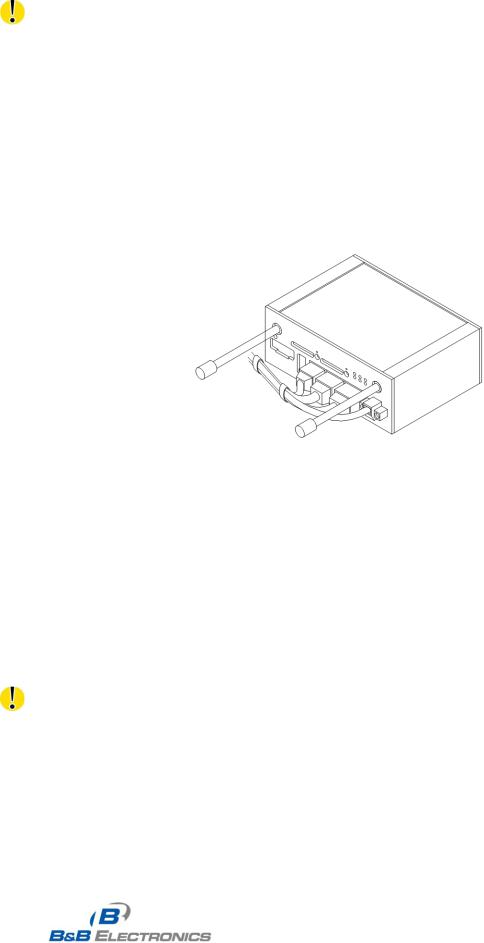
The cables should be bundled together and kept as far away from the antennas as possible.
1.Length: The combination of power supply and data cables can be a maximum of 1.5 meters.
2.If the length of the data cables exceeds 1.5 meters, overvoltage protectors (surge suppressors) should be used.
3.Do not bundle the data cables with the 120/230 VAC power cable.
4.All wiring to sensors should use shielded twisted pairs.
Fig. 4: Cable routing
Leave enough space around the connectors for the cable wiring.
13
SPECTRE_User_Manual_2912m www.bb-elec.com www.bb-europe.com

B&B Electronics, Inc. |
SPECTRE User Manual |
|
|
Fig. 5: Space in front connectors
The router must be securely grounded to earth ground for proper operation.
14
SPECTRE_User_Manual_2912m www.bb-elec.com www.bb-europe.com

B&B Electronics, Inc. |
SPECTRE User Manual |
|
|
4. User Interfaces
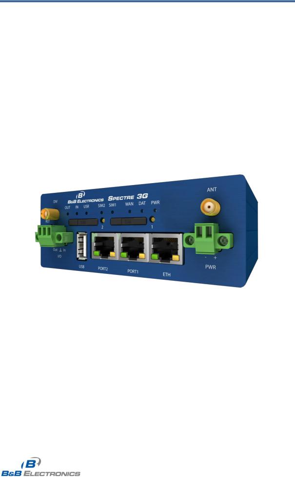
4.1Connectors
 FRONT PANEL
|
Label |
|
Connector |
|
Description |
|
|
|
|
|
|||
|
|
|
|
|||
|
|
|
|
|
||
|
PWR |
|
2-pin |
|
Power supply. |
|
|
|
|
|
|
|
|
|
|
|
|
|
||
|
ETH |
|
RJ45 |
|
Connection to the local computer network. |
|
|
|
|
|
|
|
|
|
|
|
|
|||
|
|
|
|
|||
|
PORT 1 |
|
RJ45 |
|
RS-232/422/485, ETHERNET, or I/O |
|
|
|
|
|
|||
|
|
|
|
|||
|
|
|
|
|||
|
PORT 2 |
|
RJ45 |
|
RS-232/422/485 or ETHERNET |
|
|
|
|
|
|||
|
|
|
|
|
||
|
ANT* |
|
SMA |
|
Main antenna |
|
|
|
|
|
|
||
|
|
|
|
|||
|
|
|
|
|
||
|
DIV* |
|
SMA |
|
Diversity antenna |
|
|
|
|
|
|
||
|
|
|
|
|||
|
USB |
|
USB-A Host |
|
USB connector. |
|
|
|
|
|
|||
|
|
|
|
|||
|
I/O |
|
3-pin |
|
Binary input and output. |
|
|
|
|
|
|
||
|
|
|
|
|
||
|
|
|
|
|
||
|
SIM1* |
|
- |
|
SIM card holder 1 |
|
|
|
|
|
|
||
|
|
|
|
|
|
|
|
SIM2* |
|
- |
|
SIM card holder 2 |
|
|
|
|
|
|
|
|
* 3G models only
Table 3: Front panel description
Fig. 6: Front panel SPECTRE 3G
15
SPECTRE_User_Manual_2912m www.bb-elec.com www.bb-europe.com
 Loading...