


Timer/Counter/Tachometer
User Manual

 CTA USER MANUAL
FORWORD
This user manual provides handy instructions for the operation of Delta CTA series. The detailed operational instructions help the user to easily locate the functions they would like to acquire. In addition, this user manual also helps sales and engineering staff to understand more about the advantages of Delta CTA series and assist the users to operate CTA as well as getting familiar with its functions. The date of the latest update is shown in the bottom left of the page.
CHAPTER ONE: BASIC INSTRUCTIONS
1.1 |
Features |
4 |
1.2 |
Ordering Information |
4 |
1.3 |
Specifications |
4 |
1.4 |
Display, Indicators & Keys |
5 |
1.5 |
Dimensions |
5 |
1.6 |
Terminals Definition |
5 |
1.7 |
Default Settings |
7 |
1.8 |
Easy DIP Switch Setup |
7 |
CHAPTER TWO: FUNCTIONS
2.1 |
Timer |
9 |
2.2 |
Counter |
14 |
2.3 |
Tachometer |
19 |
2.4 |
Timer + Counter (Mixed Mode) |
22 |
CHAPTER THREE: APPLICATIONS
3.1 On Cut-To-Length Machine |
23 |
2007-05-09 |
- 2 - |
© DELTA ELECTRONICS, INC. ALL RIGHTS RESERVED |

 CTA USER MANUAL
NOTES
How to use CTA correctly…
To avoid misaction caused by interference, please make sure if you isolate the I/O wiring when I/O wiring and power cable or high-voltage cable in the same wiring tube. If possible, use a separate tube for the I/O wiring.
Make sure that you place the sensor, other input devices, signal cables and CTA away from the interference source.
It will require 200ms after CTA is switched on for the activation of the internal power and default value reset. CTA may not operate normally during this period of time.
© DELTA ELECTRONICS, INC. ALL RIGHTS RESERVED |
- 3 - |
2007-05-09 |

 CTA USER MANUAL
CHAPTER ONE: BASIC INSTRUCTIONS
1.1 Features
Delta CTA series is the 3-in-1 timer, counter and tachometer with the following features:
Can be a timer, counter, or tachometer and can operate in timer + counter mixed mode.
Offers voltage input (PNP) or non-voltage input (NPN).
The Pre-Scale function allows the input pulses to be displayed in their actual units.
Counting speeds available: 1/30/200/1K/5K/10K cps. Maximum: 10K cps.
The counting can be conducted in millisecond, second, minute, minute/second and hour/minute/second.
Output 1 contains relay output and transistor output. The two types of outputs can be enabled concurrently.
Offers total counting and batch counting.
“Reset” and “Lock” keys for more convenient use.
Offers 6-digit double-line LCD display.
Offers easy DIP switch setup.
Decimal point setup available.
1.2 Ordering Information
There are currently two model types available: CTA4000A and CTA4100A, only differentiating in the type of output 2.
CTA4□00A
|
|
|
1 |
2 |
3 |
4 |
5 |
|
|
|
CTA: Delta Timer/Counter/Tachometer A series |
||||||||
|
|
|
|
|
|
|
|
|
|
|
n Panel size |
4: 48mm × 48mm |
|
|
|
|
|
||
|
|
|
|
|
|
|
|||
|
o Output 2 |
0: Transistor 1: Relay |
|
|
|
||||
|
|
|
|
|
|
|
|
|
|
|
p Preset stage |
0: 2 preset stage |
|
|
|
|
|
||
|
|
|
|
|
|
|
|
|
|
|
q Communication |
0: None |
|
|
|
|
|
||
|
|
|
|
|
|
|
|
|
|
|
\ Power supply |
A: AC100 ~ 240V |
|
|
|
|
|
||
1.3 Specifications |
|
|
|
|
|
|
|||
|
|
|
|
|
|
|
|||
Power input |
AC100 ~ 240V, 50/60Hz |
|
|
|
|
|
|||
Input voltage range |
85% to 110%, rated voltage |
|
|
|
|
|
|||
Power consumption |
Less than 10VA |
|
|
|
|
|
|||
External power supply |
12Vdc ±10%, 100mA |
|
|
|
|
|
|||
Display |
Double-line, 6-digit LCD display |
|
|
|
|
|
|||
Input signal |
Non-voltage input (NPN): ON impedance 1K ohm max. ON residual voltage: 2V max. |
||||||||
Voltage input (PNP): High level: 4.5 to 30Vdc, Low level: 0 to 2Vdc |
|||||||||
|
|
||||||||
Output 1 |
Relay: SPST max.250Vac, 5A (resistance load) |
||||||||
Transistor: NPN open collector. When 100mA /30Vdc, residual voltage = 1.5Vdc max. |
|||||||||
|
|
||||||||
Output 2 |
Relay: SPDT max.250Vac, 5A (resistance load) |
||||||||
Transistor: NPN open collector. When 100mA /30Vdc, residual voltage = 1.5Vdc max. |
|||||||||
|
|
||||||||
Dielectric strength |
2000Vac 50/60 Hz for 1 minute |
|
|
|
|
|
|||
Vibration resistance |
Without damage: 10 ~ 55Hz, amplitude = 0.75mm, 3 axes for 2 hours |
||||||||
Shock resistance |
Without damage: drop 4 times, 300m/s2, 3 edges, 6 surfaces and 1 corner |
||||||||
Ambient temperature |
0°C to +50°C |
|
|
|
|
|
|||
Storage temperature |
-20°C to +65°C |
|
|
|
|
|
|||
Altitude |
2000m or less |
|
|
|
|
|
|||
Ambient humidity |
35% to 85% RH (non-condensing) |
|
|
|
|
|
|||
Pollution degree |
Degree 2 |
|
|
|
|
|
|
||
2007-05-09 |
- 4 - |
© DELTA ELECTRONICS, INC. ALL RIGHTS RESERVED |
 CTA USER MANUAL
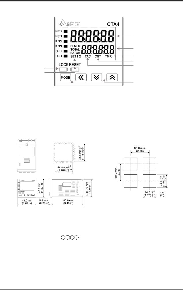
1.4 Display, Indicators & Keys
Reset 2 indicator Reset 1 indicator Key protect 2 indicator
Key protect 1 indicator
Output 2 indicator Output 1 indicator
Special function indicator 
Lock key
Reset key
Mode and number shift key 
PV(Present Value) display
SV(Set Value) display
Timer function indicator Counter function indicator Tachometer function indicator
Up/Down key
PV: Red LCD
SV and other display areas: Green LCD
H M S: Time unit for the timer
TOTAL: Total counting value
BATCH: Batch counting value
SET1 2: SV1 and SV2
1.5 Dimensions
1.6 Terminal Definition
CTA combines the functions of timer, counter and tachometer; therefore, the definitions of input terminals in different modes are slightly different. CTA has 4 terminals ready for inputs. Take the pins
in counter mode for example, 12 13 7 8 are for CP1 (A phase), CP2 (B phase) RST1 and RST2 inputs (see figure 1).
The output terminals are for OUT1 and OUT2. OUT1 has two outputs, transistor output and relay output, and the two outputs operate concurrently. The type of OUT2 is determined by the model name. For CTA4000A, OUT2 only offers transistor output with inductive load protection diode (see figure 2). For CTA4100A, OUT2 only offers relay output (see figure 3).
© DELTA ELECTRONICS, INC. ALL RIGHTS RESERVED |
- 5 - |
2007-05-09 |

 CTA USER MANUAL
CTA4 series
Counter |
Timer |
Tachometer |
Timer + Counter |
CP1 |
|
CP1 |
CP1 |
CP2 |
Gate |
|
Gate |
Reset1 |
Reset1 |
Reset1 |
Reset1 |
Reset2 |
Start |
|
Start |
Figure 1
Figure 2 |
Figure 3 |
Input connection:
NPN
PNP
Output load PIN connection:
1.When CP1, CP2, RST1 and RST2 inputs are contact inputs, please set the input type as NPN.
2.When the previous device is an open collector type, the device can adopt the 12V power supply offered by CTA for the connection.
(Relay Output) |
(Transistor Output) |
2007-05-09 |
- 6 - |
© DELTA ELECTRONICS, INC. ALL RIGHTS RESERVED |

 CTA USER MANUAL
1.7 Default Settings
There are 4 operation modes in CTA: timer, counter, tachometer and timer + counter. The table below offers the preset parameters for all functions.
|
|
Function |
Preset setting |
|
|
||
|
|
Select function |
Timer |
|
|
Timer mode |
Up (counting up) |
|
Timer |
Output mode |
Sond1 |
|
Displayed unit |
S 001 (0.01) |
|
|
Pulse width of output 1 |
0.02sec |
|
|
|
Min. width of reset |
20ms |
|
|
signal |
|
|
|
|
|
|
|
Input signal type |
NPN |
|
|
Select function |
Counter |
|
|
Counter mode |
Stage1 (1 stage) |
|
|
Input mode |
Up (counting up) |
|
|
Output mode |
F |
|
Counter |
Counting speed |
5K |
|
Position of decimal |
0 (no decimals) |
|
|
point |
||
|
|
||
|
Pre-scale value |
1.000 |
|
|
|
Save data while |
Clear |
|
|
switching off power |
|
|
|
|
|
|
|
Min. width of reset |
20ms |
|
|
signal |
|
|
|
|
|
|
|
Input signal type |
NPN |
1.8 Easy DIP Switch Setup
|
|
Function |
Preset setting |
|
|
||
|
|
Select function |
Tachometer |
|
|
Output mode |
2Lo1Lo |
|
Tachometer |
Counting speed |
5K |
|
Position of decimal point |
0 (no decimals) |
|
|
Pre-scale value |
1.000 (default) |
|
|
Delay time while switching |
0.0 (no delay) |
|
|
on power |
|
|
|
Average of input data |
0 (function disabled) |
|
|
|
||
|
|
Min. width of reset signal |
20ms |
|
|
Input signal type |
NPN |
|
|
Select function |
Mix Timer +Counter |
|
|
Input mode of timer |
Up (counting up) |
|
|
Output mode of timer |
Sond1 |
|
|
Displayed unit of timer |
S 001 0.01 |
|
|
|
|
|
+ Counter |
Input mode of counter |
Up (counting up) |
|
Output mode of counter |
F |
|
|
|
|
|
|
Counting speed |
5K |
|
|
Timer |
||
|
|
|
|
|
Pulse width of output 1 |
0.02sec |
|
|
Position of decimal point |
0 (no decimals) |
|
|
|
||
|
|
Pre-scale value |
1.000 (default) |
|
|
Save data while switching |
Clear |
|
|
off power |
|
|
|
Min. width of reset signal |
20ms |
|
|
Input signal type |
NPN |
The tables below are the DIP switches for each mode of CTA. Please be noted that in the “timer + counter” mode, setting up parameters by DIP switches are not allowed.
Timer
Switch |
Function |
OFF |
ON |
|
1 |
DIP switch |
Disabled |
Enabled |
|
2 |
Timer mode |
Counting |
Counting |
|
up |
down |
|||
|
|
|||
3 |
Output mode |
See top-right |
||
4 |
table |
|
||
|
|
|||
5 |
Displayed unit |
See bottom-right |
||
6 |
||||
table |
|
|||
7 |
|
|
||
|
|
|
||
8 |
Width of reset signal |
20ms |
1ms |
|
|
Switch 3 |
Switch 4 |
Output mode |
|
||||
|
OFF |
|
OFF |
|
Sond1 |
|
||
|
|
ON |
|
OFF |
|
Sond2 |
|
|
|
OFF |
|
ON |
|
Soffd |
|
||
|
|
ON |
|
ON |
|
Son |
|
|
|
|
|
|
|
||||
Switch 5 |
|
Switch 6 |
Switch 7 |
Displayed unit |
||||
OFF |
|
OFF |
OFF |
0.01 sec. |
||||
ON |
|
OFF |
OFF |
0.1 sec. |
||||
OFF |
|
ON |
OFF |
1 sec. |
||||
ON |
|
ON |
OFF |
min., 0.01 sec. |
||||
OFF |
|
OFF |
ON |
min., 0.1 sec. |
||||
ON |
|
OFF |
ON |
0.1 min. |
||||
OFF |
|
ON |
ON |
minute |
||||
ON |
|
ON |
ON |
hr., min., sec. |
||||
© DELTA ELECTRONICS, INC. ALL RIGHTS RESERVED |
- 7 - |
2007-05-09 |

 CTA USER MANUAL
Counter
|
Switch |
Function |
OFF |
|
|
ON |
|
|
1 |
DIP switch |
Disabled |
|
|
Enabled |
|
|
2 |
Counting mode |
Counting |
|
Counting |
|
|
|
up |
|
|
down |
|
||
|
|
|
|
|
|
||
|
3 |
Output mode |
See the table on |
|
|||
|
4 |
the right |
|
|
|
|
|
|
|
|
|
|
|
||
|
5 |
Counting speed |
30cps |
|
|
10Kcps |
|
|
6 |
Reserved |
- |
|
- |
|
|
|
7 |
Input signal |
NPN |
|
|
PNP |
|
|
8 |
Width of reset signal |
20ms |
|
|
1ms |
|
|
Tachometer |
|
|
|
|
|
|
|
|
|
|
|
|
|
|
|
Switch |
Function |
OFF |
|
|
ON |
|
|
1 |
DIP switch |
Disabled |
Enabled |
|
||
|
2 |
Reserved |
- |
|
|
- |
|
|
3 |
Output mode |
See the table on |
|
|||
|
4 |
the right |
|
|
|
|
|
|
|
|
|
|
|
||
|
5 |
Counting speed |
30Hz |
|
|
10KHz |
|
|
6 |
Reserved |
- |
|
|
- |
|
|
7 |
Input signal |
NPN |
|
|
PNP |
|
|
8 |
Width of reset signal |
20ms |
|
|
1ms |
|
Switch 3 |
Switch 4 |
Output mode |
OFF |
OFF |
F |
ON |
OFF |
N |
OFF |
ON |
C |
ON |
ON |
R |
Switch 3 |
Switch 4 |
Output mode |
|
OFF |
OFF |
Lo-Lo |
|
ON |
OFF |
Lo-Hi |
|
OFF |
ON |
Hi-Lo |
|
ON |
ON |
Hi-Hi |
When Switch 1 is enabled (ON), the parameters can only be set up by Switch 1 ~ Switch 8 and cannot be modified in the system. If the parameters have to be set in the system, please disable Switch 1 (OFF).
2007-05-09 |
- 8 - |
© DELTA ELECTRONICS, INC. ALL RIGHTS RESERVED |
 Loading...