


AFI4
www.baumer.com
Operators Instruction: 11126179 00 Page 1 / 36
CombiLyz, AFI4
Operators Instruction
EN/2014-04-29 Design and specifications subject to change without notice
CombiLyz AFI4 conductivity transmitter is a compact sensor/transmitter,
based on inductive technology, which is designed and produced to meet
the requirements in hygienic and general industry where measuring of
medium range conductivity is used.
Description
Safety instruction
This instrument is built and tested according to the current EU-directives
and packed under technically safe conditions. In order to maintain these
conditions and to ensure safe operation, the user must follow the hints
and warnings given in this instruction.
During the installation the valid national rules have to be observed. Ig-
noring the warnings may lead to severe personal injury or substantial
damage of property.
The product must be operated by trained staff. Correct and safe opera-
tion of this equipment is dependent on proper transport, storage installa-
tion and operation.
All electrical wirings must conform to local standards. In order to prevent
stray electrical radiation, we recommend twisted and shielded input
cables and also to keep power supply cables separated from the input
cables. The connection must be made according to the connection dia-
grams.
Before switching on the power supply take care that other equipment is
not affected. Ensure that the power voltage, the conditions are the envi-
ronment comply with the specification of the device.
Before switching off the power supply voltage, check the possible effects
on other equipment and the processing system.
WARNING
The device is not approved for electrical installations in explosion proof
areas.
After mounting of the device - do check that the housing has a ground
potential.
The product contains no direct replaceable parts, except for the DFON
display. In case of malfunction the product must be sent to Baumer for
repair.
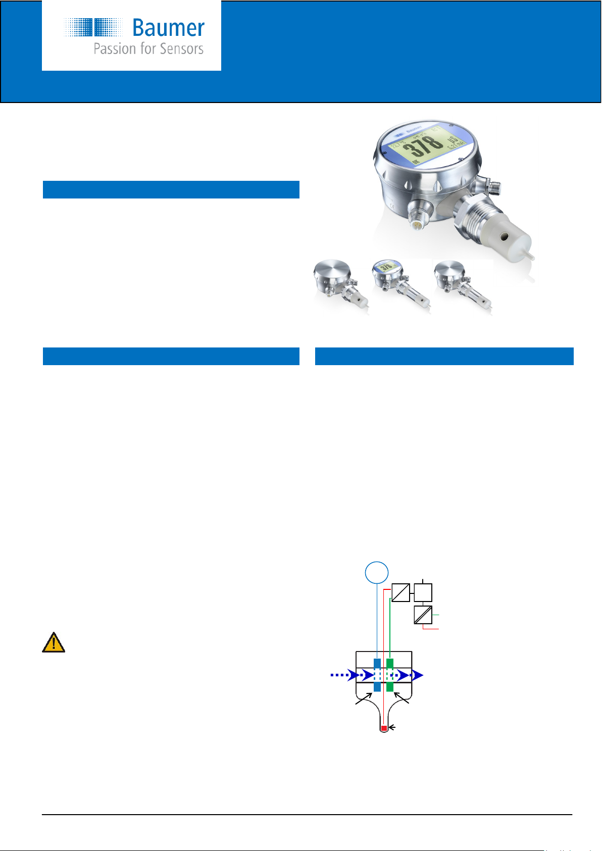
CombiLyz AFI4 consists of a conductivity sensor and a transmitter built
into one compact unit.
The output from the transmitter are two 4...20 mA, which is available for
both conductivity, concentration and temperature.
The display features more user selectable modes and user specified
“product labels” and warnings. Further there are two switch outputs for
alarms or control.
The background colour can be set in three colours, white, green or red
- steady or flashing, controlled by the alarm settings. The transmitter and
display can be programmed by either the touch screen on the display or
by the FlexProgrammer programming unit and software.
The measuring cell is a homogeneous sealed body all in PEEK.
Through the body is a hole, through which the media is flowing. Built-in
around the hole are two coils; a primary coil supplied with an AC volt-
age and a secondary coil, which picks up a small signal through the
media inducted voltage. The size of this voltage is dependent on the
conductivity of the media. This signal is handled and amplified in the
electronics to a linear analogue 4...20 mA output signal. Also built into
the body is a Pt100 sensor placed in the tip of the sensor. This is meas-
uring the media temperature to enable temperature compensation of
the conductivity signal, which is very temperature dependent. The
Pt100 sensor signal also features an analogue 4...20 mA output signal.
The coils and sensor are encapsulated in the PEEK sensor body, which
have a surface with surface roughness (Ra) <0,8 µm. It is therefore well
suited for use in hygienic processes or direct in concentrated acids or
alkalis.
Media
Primary coil Secondary coil
Pt100
~
CPU
D
A
VAC
Range setting
input R1 and R2
Conductivity/Concentration
4...20 mA output
4...20 mA output
Temperature
A
D
Working principle
English
English page 1...11
Deutsch Seite 12...22
Français page 23...33
www.baumer.com
Operators Instruction: 11126179 00 Page 2 / 36
Operators Instruction
Electrical specifications
Technical specifications
Housing FlexHousing, Ø80 mm
Material Stainless steel, AISI 304
Process connection G1A, rotating
(for other connections see adapters page 4)
Insertion length Standard 37 mm / 3A version 40,5 mm
Long version 83 mm / 3A version 87 mm
Material Not wetted Stainless steel AISI 304
Wetted parts 37… mm PEEK natura
83... mm PEEK narura+AISI 316L
Surface Wetted parts Ra <0,8 µm
Measuring range Conductivity 0...500 µS/cm … 0…1.0 S/cm
14 selectable ranges
Concentration 4 factory set medias/ranges
1 customer defined media/range
Temperature -30...150°C
Free programmable range
Accuracy Cond./conc. 0...500 µS/cm ≤1,5%
(sensor incl. transmitter) 0...1 / 0...500 mS/cm ≤1,0%
0...1 S/cm ≤1,5%
Temperature ≤0,4% selected range
Temperature compensation 0,0...5,0%/°C, free adjustable
Compensation range -20...150°C
Reference temperature 25°C (adjustable)
Response time Cond./conc. <2,0 seconds
Temperature, t
90
<15 seconds
Start up time without display ≤10 seconds
Start up time with display ≤15 seconds
General specifications
Media temperature -20...140°C
150°C up to 1 hour
Media pressure <10 bar (helium tested)
Ambient temperature Without display -40...85°C
With display -30...80°C
Isolation voltage 500 VAC
Protection class IEC 529 IP 67 / IP 69K
Humidity IEC 68.2.38 98% condensing
Vibrations IEC 60068.2.6 - test Fc
1,0 mm
(2-13,2 Hz)
0,7g
(13,2-100 Hz)
Power supply 15...35 VDC
Output Cond./Conc. 4...20 mA
4...20 mA + HART
®
(pending)
Temperature 4...20 mA
Relay 2 relays included in the display
Temperature drift ≤0,1%/°C
El. connection Left side M12, 5-pin
M16 or M20 cable gland
Right side M12, 5-pin
(4...20 mA output only)
M12, 8-pin
(4...20 mA + relay output)
M16 or M20 cable gland
Material Plastic
Stainless steel
Apply to EU directives 10/2011, 1935/2004, 2023/2006
FDA PEEK: CFR 21.177.2415
Approvals 3A approval 74-06
EHEDG (pending)
Compliance and approvals
Product marking
The marking on the product is made by laser engraving.
Below see example:
Contacts 2 × solid state relays
Voltage 60 V
p
Relay
Display
Type FSTN Graphically LCD
Measuring range -9999...99999
Digit height Max. 22 mm
Temperature drift ≤0,0001%/°C inside optimal range
-10...70°C
≤0,00015%/C outside optimal range
-30…-10 / 70...80°C
Mechanical data
Material Polycarbonate plastic
Protection class IP 10 on terminals
IP67/IP69K in FlexHousing
English
CombiLyz, AFI4
www.baumer.com
Operators Instruction: 11126179 00 Page 3 / 36
Operators Instruction
Set-up the AFI4
Typical temperature dependence
Media % change per °C
Acids 1,0 … 1,6
Bases 1,8 … 2,2
Salts 2,2 … 3,0
Neutral water 2,0
AFIx
range
Conductivity in different media:
Conductivity Media group Media
55 nS/cm Water Ultra-pure water
1 µS/cm Pure water
10 µS/cm Process water
100 µS/cm Food Drinking water
Beer
1 mS/cm Milk
Orange juice
10 mS/cm Apple juice
100 mS/cm Process Phosphoric acid
Hydrochloric acid
Conductivity ranges (selectable)
0…500 µS/cm
0...1 mS/cm 0...10 mS/cm 0...100 mS/cm 0...1 S/cm
0...2 mS/cm 0...20 mS/cm 0...200 mS/cm
0...3 mS/cm 0...30 mS/cm 0...300 mS/cm
0...5 mS/cm 0...50 mS/cm 0...500 mS/cm
Definition: 1.000 µS/cm = 1.0 mS/cm
1.000 mS/cm = 1.0 S/cm
Concentration ranges (selectable)
Range R1 R2 Range R1 R2
1 N.C. N.C. 3 N.C. 24 VDC
2 24 VDC N.C. 4 24 VDC 24 VDC
To set the external input for range selection
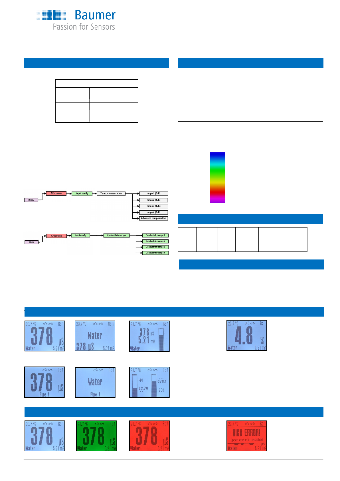
White background Green background Red background Error message and red background
Selectable display views Conductivity Concentration
Visual alerts and colours
Value w. all values Media w. values Bar graph w. values Concentration value in %
same views available as for conductivity
Value w. TAG Media w. TAG Bar graph incl. temp.
NaOH (caustic soda) 0...15% by weight (0...90°C)
25...50% by weight (0...90°C)
HNO
3
(nitric acid) 0...25% by weight (0...80°C)
36...82% by weight (0...80°C)
1 × customer defined (30 point linearization)
Conductivity measurement is very temperature dependent.
The factory set-up is 2,0%/°C.
This means that the AFIx will automatically compensate with this fac-
tor. If the temperature dependence is known for the media this factor
must be set. However if the factor is unknown, it is recommended to
use an average from above table.
It is possible to adjust the temperature compensation factor from 0,0 …
5,0 %/°C.
Configure the temperature compensation by the touch screen:
Configure the range by the touch screen:
Configuration by the FlexProgram and FlexProgrammer please see
HELP in the FlexProgram.
Concentration output can also be selected by the touch screen or pro-
grammed by the FlexProgram.
Programming of the display colours, warnings and relays can be done
by the touch screen (see page 8 and 9) or by the FlexProgrammer.
English
CombiLyz, AFI4
www.baumer.com
Operators Instruction: 11126179 00 Page 4 / 36
Operators Instruction
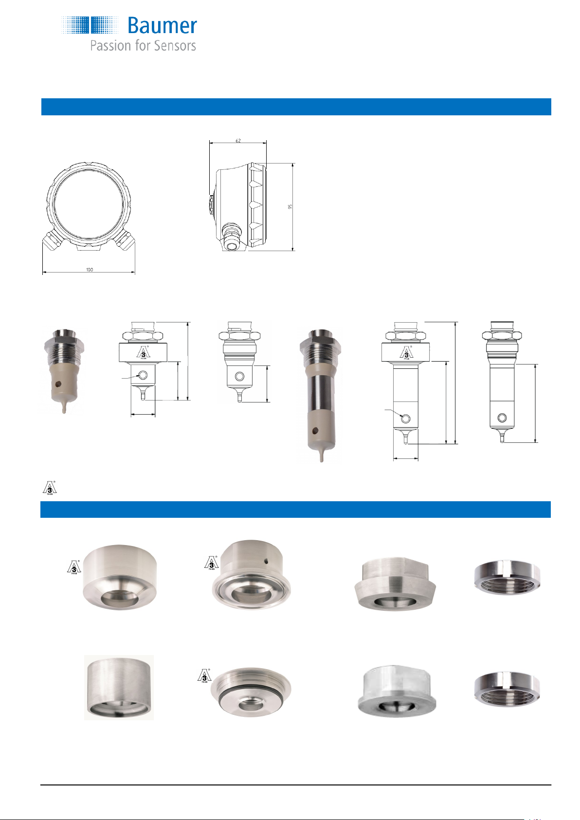
Dimensions
Welding connection Clamp connection Screwed connections Union nut
Short version 3A versions Standard Long version 3A versions Standard
40,5 mm 37 mm 87 mm 83 mm
G1” mounting adapters
DN 40...50 PM052-1 Variline, type N VAM053 SMS 1145 DN 38 SAM-038-1 SNF038
DN 65...150 PM052-2 SMS 1145 DN 51 SAM-051-1 SNF051
More adapters are available, e.g. with standard industrial thread. Please see data sheet for Accessories.
For tank
For tube
PM053 ISO 2852 DN38 CAM050-505 DIN 11851 DN 32 MAM050-032 MNF032
ISO 2852 DN51 CAM050-640 DIN 11851 DN 40 MAM050-040 MNF040
DIN 11851 DN 50 MAM050-050 MNF050
The two above sensors are 3A approved when mounted in one of below 3A approved G1” mounting adapters
Front view Bottom connection
Ø6,6
Ø25,5
87
128
83
37
Ø6,6
Ø25,5
40,5
82
English
CombiLyz, AFI4
www.baumer.com
Operators Instruction: 11126179 00 Page 5 / 36
Operators Instruction
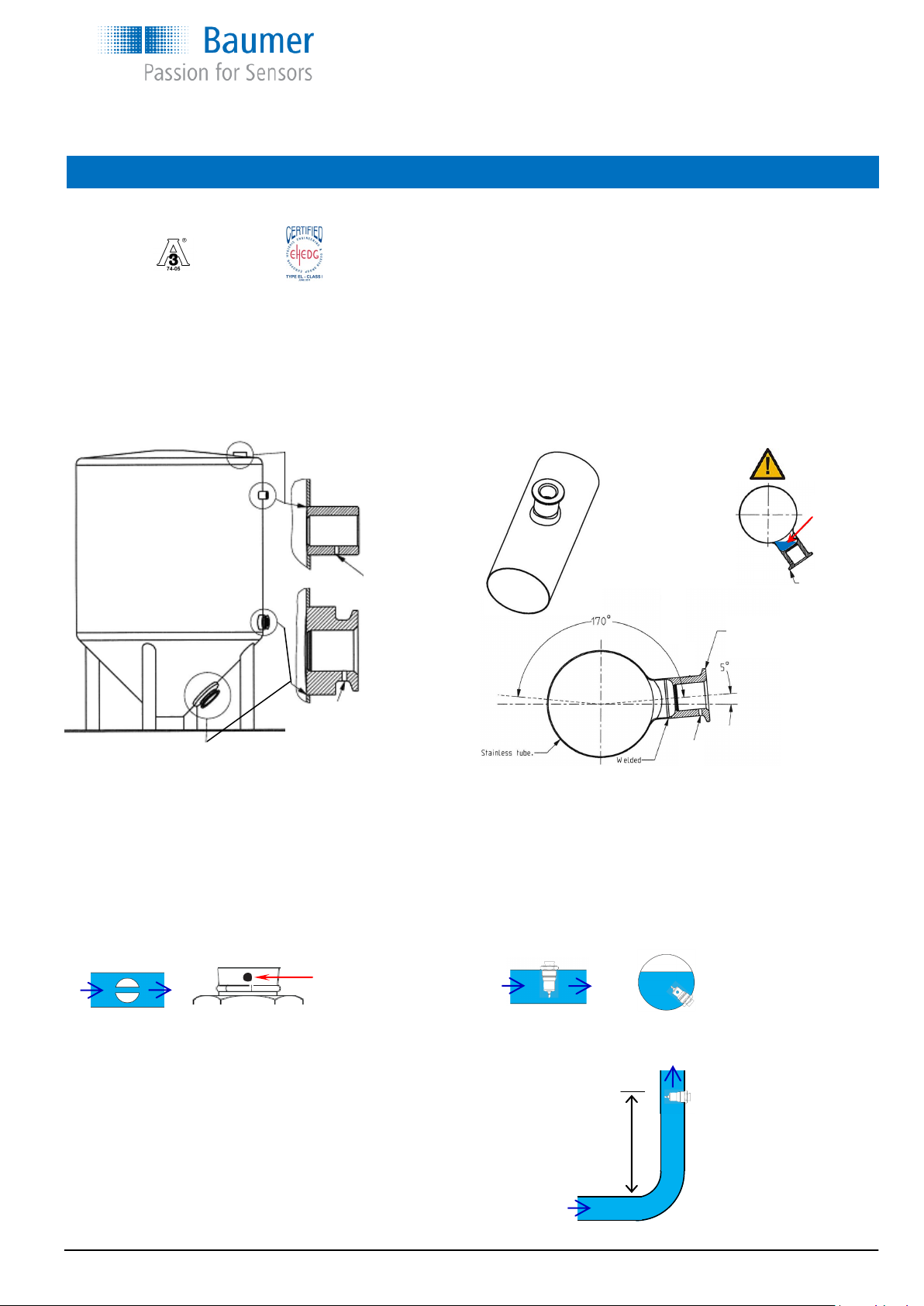
Installation of 3A approved and EHEDG certified products:
1) Use only a 3A approved counter part
2) The inspection hole should be visible and drained
3) Mount the adapter in a self drained position/angle
4) Level the inner surface of the pipe with the counter part.
After installation
Check the leak tightness of the sleeve.
Check the tightness of glands or M12 plugs.
Check the tightness of the cover
Mounting
Example
with PM060-2
Example with
PM023 or PM053
Example
with PM060-1
Leakage indication hole
must be places downwards
Fitted
incorrect
Cannot be
drained
WARNING
5) The 3A mark or the arrow shall be placed upwards
6) Welding should be grinded to Ra= 0.8
7) Tighten the swirling nipple on the AFIx 20...25 Nm
8) Installed with correct torque the electrical connection
will point downwards
≥1 meter
The sensor must be fully submersed in the media.
To avoid turbulence problems the sensor is recommended to mount in
a distance of >1 meter from a bend.
The hole through the sensor must be in the flow direction
The marks on the
connection must
point in flow direction
There must be some bi-directional flow through the hole to ensure a
homogeneous media - i.e. correct measurement. There must be no
air-bubbles in the hole.
English
CombiLyz, AFI4
www.baumer.com
Operators Instruction: 11126179 00 Page 6 / 36
Operators Instruction
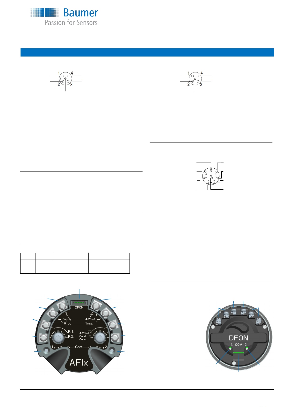
Electrical connection
Left side M12, 5-pin connector
1: Brown Supply (+) (15...35 vdc)
2: White Cond. (-) (4...20 mA)
3: Blue Supply (-) (15...35 vdc)
4: Black Cond. (+) (4...20 mA)
5: NC Not connected
Cond. (+) - 4
15...35 vdc (-) - 3
5 NC
1 - 15...35 vdc (+)
2 - Cond. (-)
Left side electrical connection (Front view) Right side electrical connection (Front view)
°C (+) - 4
R2 - 3
5 NC
1 - R1
2 - °C (-)
Right side M12, 5-pin connector
1: Brown R1 (external input)
2: White Temp. (-) (4...20 mA)
3: Blue R2 (external input)
4: Black Temp. (+) (4...20 mA)
5: NC Not connected
4 - Relay 2
3 - Relay 2
2 - Temp (+) (4...20 mA)
8 - R2 (external input)
Right side M12, 8-pin connector
1: White R1 (external input)
2: Brown Temp. (+) (4...20 mA)
3: Green Relay 2
4: Yellow Relay 2
5: Grey Relay 1
6: Light red Relay 1
7: Blue Temp. (-) (4...20 mA)
8: Red R2 (external input)
Right side electrical connection with relay output
Electrical connection on the display with relay output
1: Not connected
2: Not connected
3: Green Relay 2
4: Yellow Relay 2
5: Grey Relay 1
6: Light red Relay 1
(3 + 5 can be connected
common)
UnitCom Ribbon cable
to transmitter
To connect the
FlexProgrammer
COM 1 Red clip
COM 2 Black clip
DFON (UnitCom)
Supply + Temp. +
Supply - Temp. -
R1
Cond. +
R2 Cond. -
Com 1 Com 2
N.C. N.C.
Relay 2 Relay 1
Com 1 Com 2
UnitCom
Note:
If a M12 5-pin connector for left and right side is selected the
AFI4 is direct compatible with the old Baumer ISL conductivity
transmitter.
To connect the FlexProgrammer to the transmitter
Com 1 Red clip
Com 2 Black clip
The data entered to the transmitter will automatically be uploaded to
the DFON display via the ribbon cable (UnitCom)
To connect the FlexProgrammer to the DFON display
Com 1 Red clip
Com 2 Black clip
For setting the colour changes, error messages, relay set-points etc.
To set the external input for range selection
Relay 1 - 5
Relay 1 - 6
Temp. (-) (4...20 mA) - 7
R1 (external input) - 1
Range R1 R2 Range R1 R2
1 N.C. N.C. 3 N.C. 24 VDC
2 24 VDC N.C. 4 24 VDC 24 VDC
English
CombiLyz, AFI4
Note:
For ranges below 10 mS/cm a shielded cable must be used.
www.baumer.com
Operators Instruction: 11126179 00 Page 7 / 36
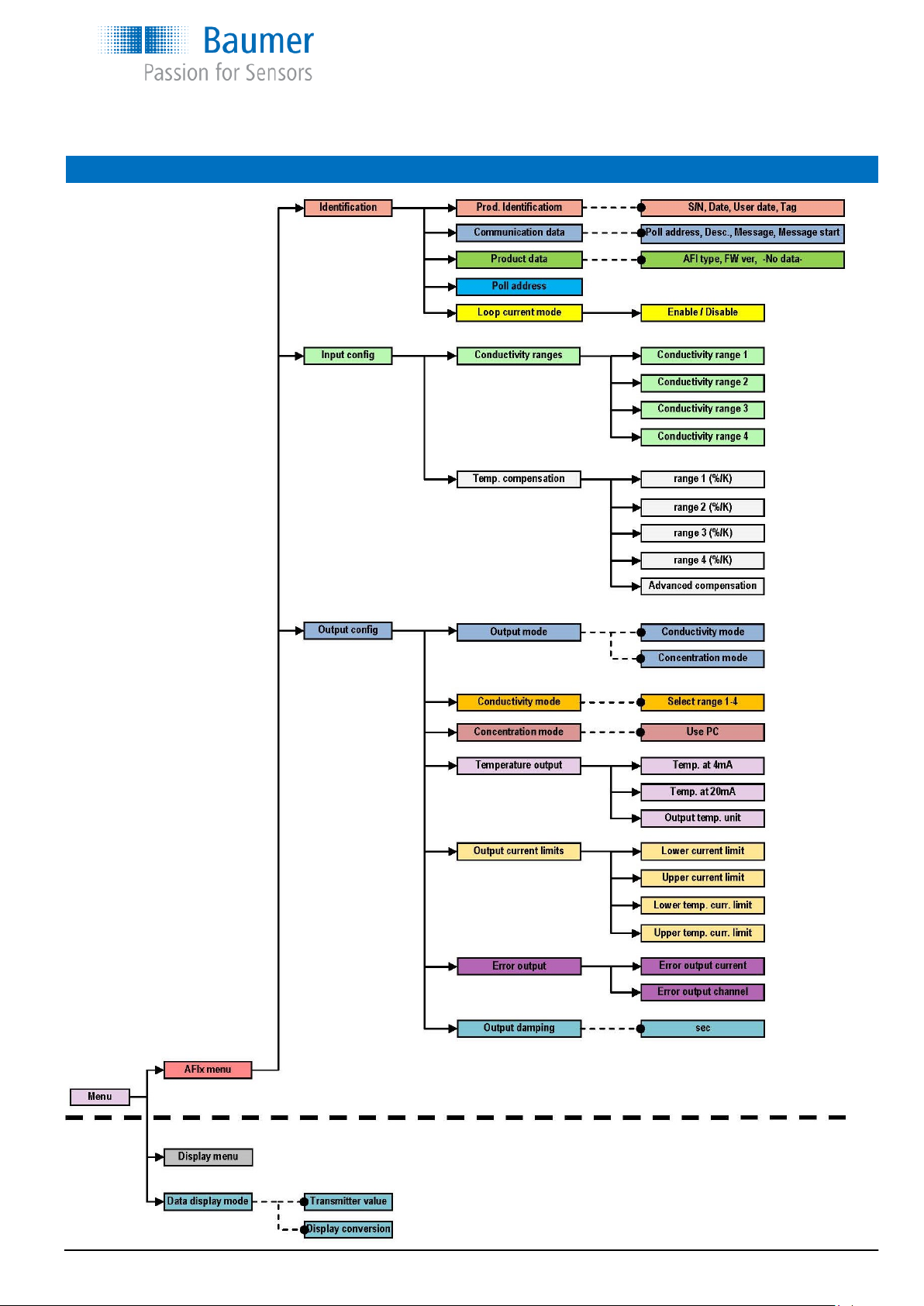
Programming the CombiLyz AFIx with touch screen on DFON display
Operators Instruction
English
CombiLyz, AFI4
www.baumer.com
Operators Instruction: 11126179 00 Page 8 / 36
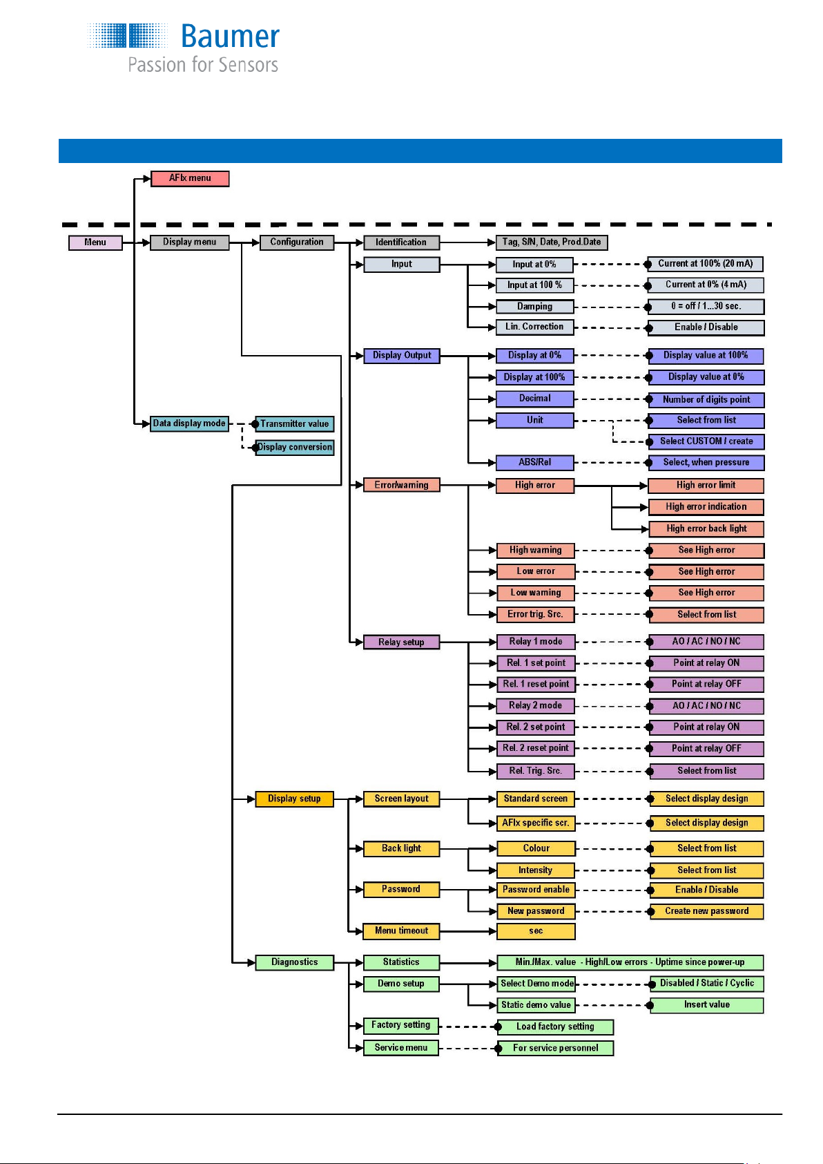
Programming the touch screen on DFON display on CombiLyz AFIx
Operators Instruction
English
CombiLyz, AFI4
www.baumer.com
Operators Instruction: 11126179 00 Page 9 / 36
Operators Instruction
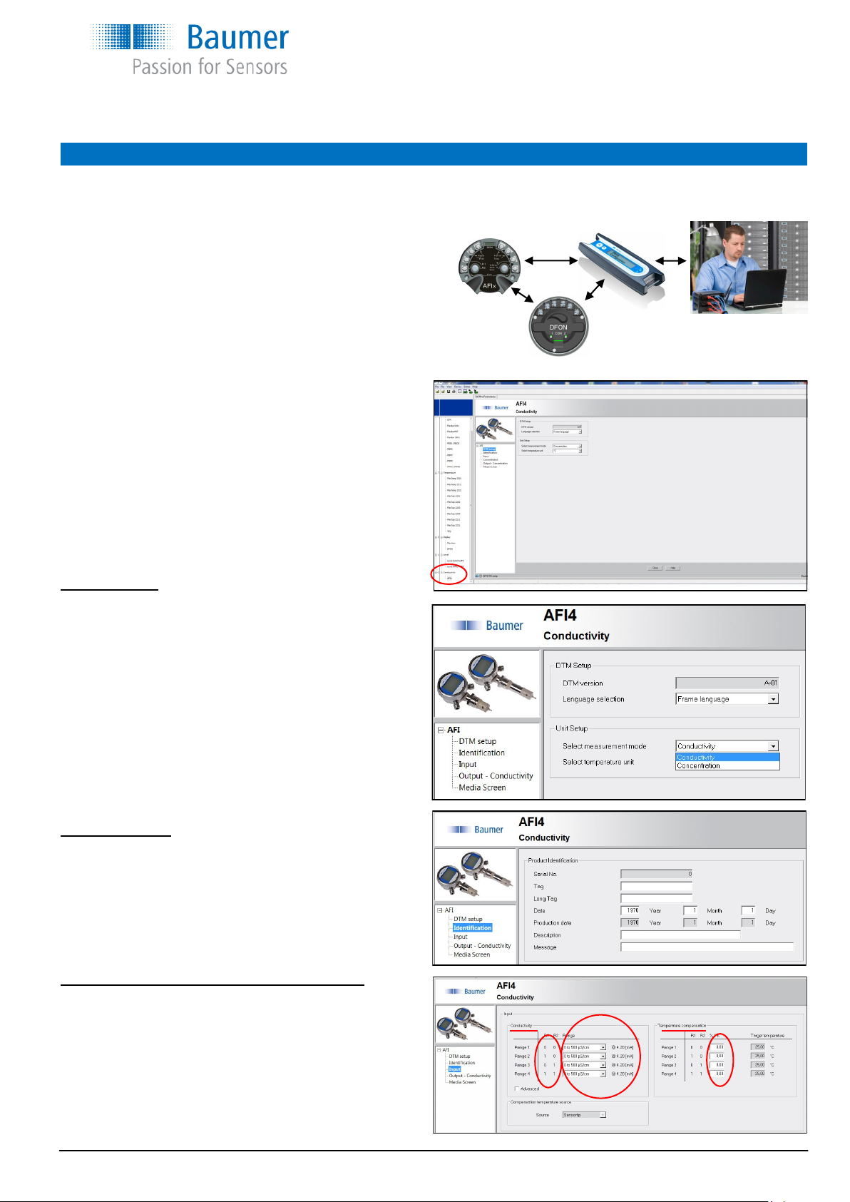
Programming the AFI4 with the FlexProgram
Open the FlexProgram
Select AFIx in the bottom and this screen will appear
Screen DTM setup
It is recommended to select
- “Frame language”
Select measurement mode:
- Conductivity or Concentration
Temperature unit °C or °F can also be selected.
Screen Identification
Enter TAG number Tag: 8 characters
Long tag: 30 characters
Date of 1
st
use (year/month/date)
Description (16 characters)
Message (32 characters)
Screen Input (when conductivity is selected in DTM setup)
Setting for the 4 conductivity ranges. Selectable from drop
down menu with 14 defined ranges.
Factory setting will be
0...200 mS/cm
0… 20 mS/cm
0… 2 mS/cm
0…500 µS/cm
How to connect the external input R1 and R2 is defined
in front of the ranges. (0=Not Connected / 1=24VDC)
All settings can be individually programmed with the Baumer FlexProgram and programming unit FlexProgrammer 9701. All parameters, such as
conductivity range, concentration and output type, diagnostics, data logging, tag no., damping etc. can be configured using the FlexProgrammer
9701.
Integrated HELP-menus will give full instruction.
The programming entered to the AFIx transmitter will automatically
be uploaded to the DFON display through the UnitCom ribbon cable,
if Transmitter Value is selected in the programme or by the touch screen.
If Display Conversion is selected the DFON display can be programmed
individually, e.g. with other engineering units or ranges.
English
CombiLyz, AFI4
www.baumer.com
Operators Instruction: 11126179 00 Page 10 / 36
Operators Instruction
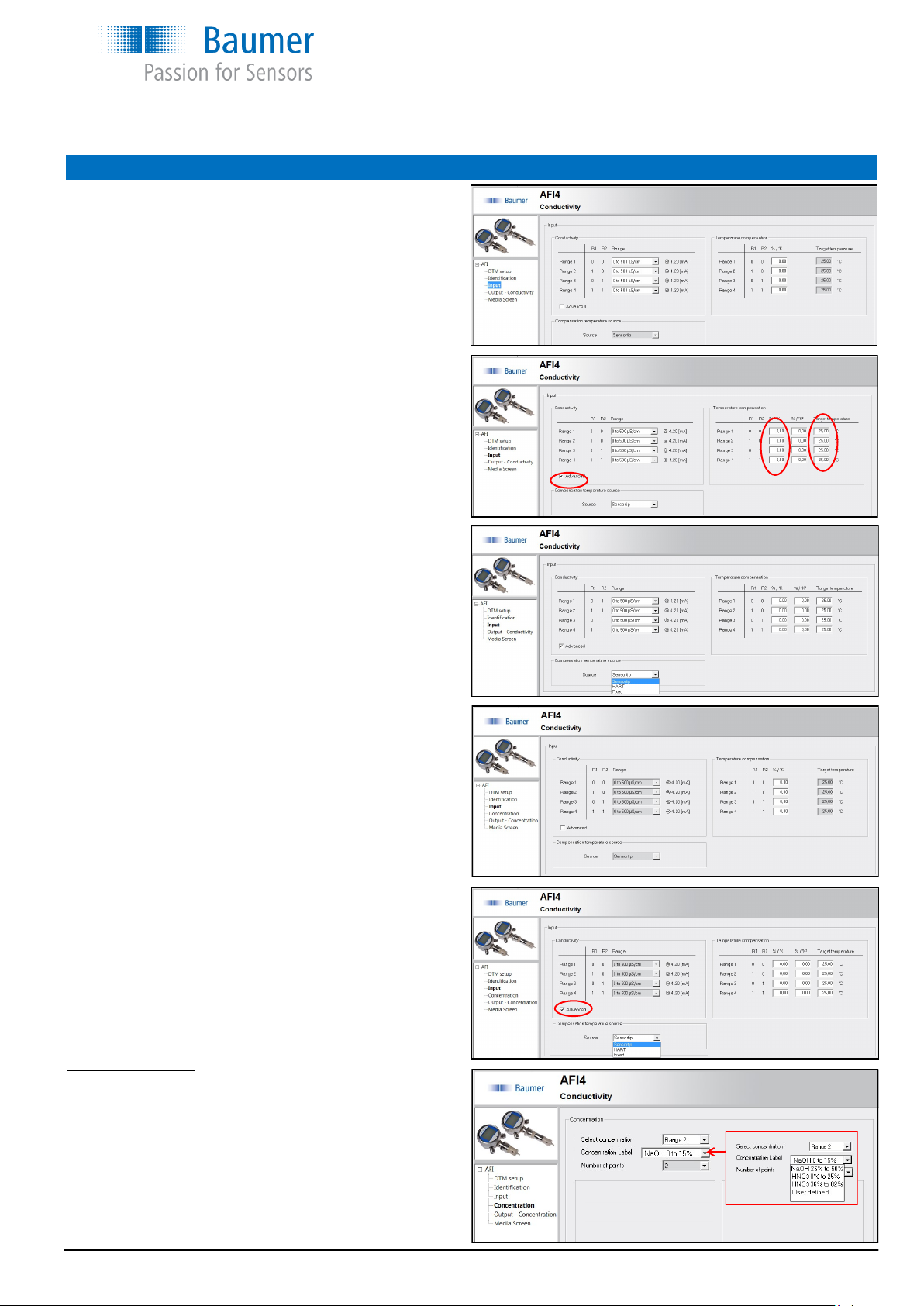
Programming the AFI4 with the FlexProgram
Setting of Temperature compensation for each range.
This will be factory set to 2%/°C as default.
If the box Advanced is ticked, it will be possible to enter an
other target temperature. This is as default set to 25°C, which is the
most common target temperature for most media. If another target
temperature is wanted, it can be entered.
NOTE:
This is not the specific media temperature, but the
“0-point” for the temperature compensation.
When the “Advanced” is ticked the “Compensation temperature
source” is accessible.
You can enter a value to the column %/K
2
you will create a unlinear
curve.
These fields are not necessary to change for standard measurement.
Be careful if changing the default values, as wrong values in those
fields may course wrong measurement.
It is possible to select from where the temperature measuring shall
come from
Sensor tip (built in Pt100)
HART (external input via HART)
Fixed (no temperature measurement)
Screen Input (when concentration is selected in DTM setup)
No settings in this screen will be available as standard.
When user defined concentration is selected in screen concentration,
it will be possible to adjust temperature concentration.
The default setting will be 2%/°C.
Advanced settings
Here only “Compensation temperature source” will be available.
Screen Concentration
There is 4 selectable medias, for which the calibration curves
is default entered from factory.
NaOH (caustic soda) 0...15% by weight
NaOH - 25...50% by weight
HNO
3
(Nitric acid) 0...25% by weight
HNO
3
36...82% by weight
For user defined, please see next page.
English
CombiLyz, AFI4
www.baumer.com
Operators Instruction: 11126179 00 Page 11 / 36
Operators Instruction
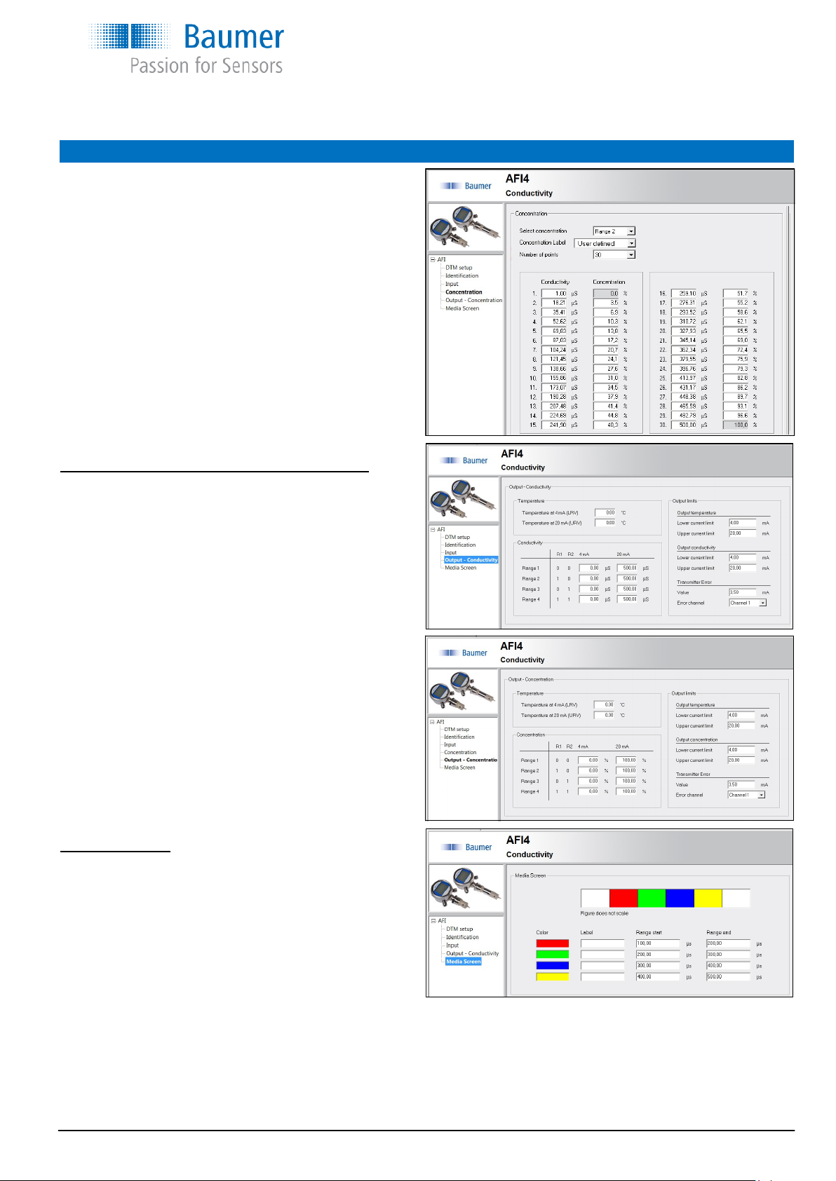
Programming the AFI4 with the FlexProgram
If user defined concentration is selected you may enter the number of
point (2...30 points) in which the media is to be calibrated.
Fill in conductivity in µS/cm and % for each point.
See example to the right.
Screen Output (when conductivity is selected in DTM setup)
Setting the temperature output range (4...20 mA)
Setting the conductivity µS/cm or mS/cm output 4 ranges (4...20 mA)
The ranges set under Input will appear, however can be overwritten if
wanted.
The transmitter error signal can be directed to either temperature out-
put or conductivity output or both outputs.
Screen Output
(when concentration is selected in DTM setup)
Setting the temperature output range (4...20 mA)
Setting the concentration % output 4 ranges (4...20 mA)
The ranges set under Input will appear, however can be overwritten if
wanted.
The transmitter error signal can be directed to either temperature out-
put or conductivity output or both outputs.
Screen Media screen
A product label can be entered in field “Label” e.g. Milk
and the values for the media entered in µS/cm in the two following
fields. Then the “Label” will appear on the display between the two
values (see media screens page 3)
(The colours is only informative, they will not appear on the display)
Example:
Water 600 µS/cm 700 µS/cm
Milk 4500 µS/cm 5500 µS/cm
CIP acid 9000 µS/cm 11000 µS/cm
CIP caustic 55000 µS/cm 65000 µS/cm
English
CombiLyz, AFI4
 Loading...