


Owner’s Manual & Safety Instructions
Save This Manual Keep this manual for the safety warnings and precautions, assembly, |
|
operating, inspection, maintenance and cleaning procedures. Write the product’s serial number in the |
|
back of the manual near the assembly diagram (or month and year of purchase if product has no number). |
|
Keep this manual and the receipt in a safe and dry place for future reference. |
19e |
When unpacking, make sure that the product is intact and undamaged. If any parts are missing or broken, please call 1-888-866-5797 as soon as possible.
Copyright© 2019 by Harbor Freight Tools®. All rights reserved.
No portion of this manual or any artwork contained herein may be reproduced in any shape or form without the express written consent of Harbor Freight Tools. Diagrams within this manual may not be drawn proportionally. Due to continuing improvements, actual product may differ slightly from the product described herein. Tools required for assembly and service may not be included.
Read this material before using this product. Failure to do so can result in serious injury. SAVE THIS MANUAL.
Table of Contents
Specifications |
............................................................2 |
Maintenance ............................................................. |
14 |
Safety ........................................................................ |
3 |
Parts List and Diagram ............................................. |
18 |
Setup ......................................................................... |
6 |
Warranty ................................................................... |
20 |
Operation.................................................................. |
13 |
|
|
Specifications
Rated Single |
12,000 lb (5443 kg) |
|
Line Pull |
||
|
||
Application |
Vehicle Recovery / |
|
For Trucks and SUV’s |
||
|
||
Motor |
12 VDC Series Wound |
|
Power IN & |
Yes |
|
Power OUT |
||
|
||
Duty Cycle Rating |
5% (45 sec at Max Rated Load; |
|
14 min, 15 sec Rest) |
||
|
||
Remote Control |
Wireless / Wired, 12 ft (3.7 m) long |
|
Gear Train |
3-Stage Planetary |
|
Gear Ratio |
210:1 |
|
Freespool |
Rotating Ring Gear |
|
Brake |
Automatic Load Holding |
|
Drum (Dia. X L) |
2.5" x 8.8" (64 mm x 224 mm) |
|
Clevis Hook |
3/8", Replaceable with |
|
Spring-loaded Safety Latch |
||
|
Fairlead |
Aluminum Fairlead |
|
Sound Rating |
85 dB |
|
Synthetic Rope |
Ø0.375" x 80' (Ø 9.5 mm x 24.4 m) |
|
Size / Type |
||
|
||
Battery |
12 VDC Minimum 650 CCA |
|
Battery Cables |
Minimum 2 AWG x 6' |
|
Mounting Bolt |
10" x 4.5" (254 mm x 114.3 mm) |
|
Pattern |
||
|
||
|
Winch: |
|
Mounting |
8 x Gr8.8, M10 x 30 mm |
|
Hardware |
Fairlead: |
|
|
2 x Gr8.8, M12 x 40 mm |
|
Overall Dimensions |
23.2" x 6.67" x 9.96" |
|
(L x D x H) |
(590 mm x 169.5 mm x 253 mm) |
|
Shipping Weight |
80 lb (36.2 kg) |
|
IP Rating |
IP68 / IP69K |
Layer |
Rated Line Pull |
Synthetic Rope Capacity |
1 |
12000 lb (5443 kg) |
16.3' (5 m) |
2 |
9517 lb (4317 kg) |
37' (11 m) |
3 |
7885 lb (3577 kg) |
60' (18.3 m) |
4 |
6732 lb (3053 kg) |
80' (24.4 m) |
First Layer of Synthetic Rope Performance
|
|
|
Line Pull lb (kg) |
Line Speed fpm (mpm) |
Amp Draw (@ 12V) |
||
|
|
|
0 |
(0) |
31.5 |
(9.6) |
60 |
1 |
|
3000 |
(1361) |
12.1 |
(3.7) |
166 |
|
|
6000 |
(2722) |
8.9 |
(2.7) |
259 |
||
|
|
|
|||||
|
|
|
|
|
|
|
|
|
|
|
9000 |
(4082) |
6.7 |
(2.0) |
349 |
|
|
|
12000 |
(5443) |
4.7 |
(1.43) |
448 |
Page 2 |
For technical questions, please call 1-888-866-5797. |
Item 56385 |
WARninG SyMBOLS AnD DeFiniTiOnS
This is the safety alert symbol. It is used to alert you to potential personal injury hazards. Obey all safety messages that
follow this symbol to avoid possible injury or death.
Indicates a hazardous situation which, if not avoided, will result in death or serious injury.
Indicates a hazardous situation which, if not avoided, could result in death or serious injury.
Indicates a hazardous situation which, if not avoided, could result in minor or moderate injury.
Addresses practices not related to personal injury.
SAFeTy
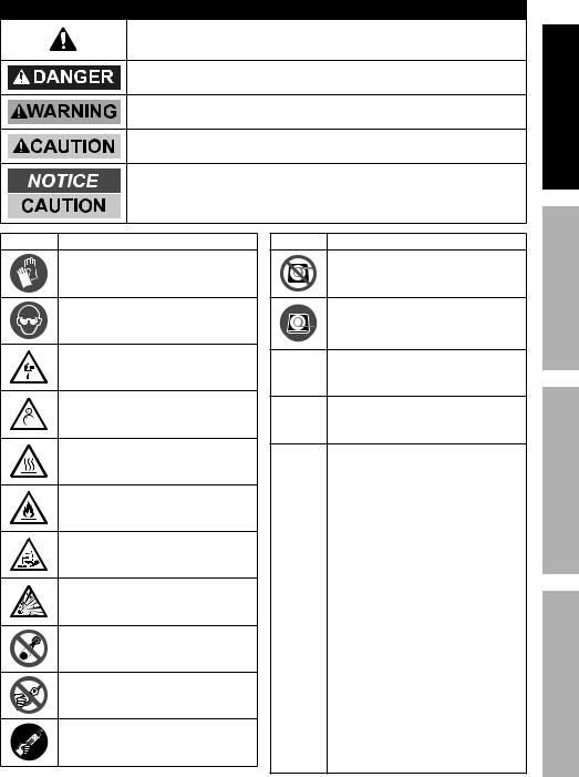
Symbol |
Property or Statement |
Wear heavy-duty, cutand abrasion-resistant leather gloves.
Wear AnSi-approved safety glasses.
Cut or sever hazard.
Roller entanglement hazard.
Hot surface burn hazard.
Fire hazard.
Caustic chemical (acid) hazard.
explosion hazard.
Do not loop the synthetic rope around object and hook onto itself.
Do not place finger(s) through hook. Fingers may be caught and get pulled into fairlead or drum.
Pull hook using strap only.
Symbol |
Property or Statement |
Do not use winch in overwind orientation. (Synthetic rope enters/exits at the top.)
use winch only in underwind orientation. (Synthetic rope enters/ exits at the bottom.)
VDC Volts Direct Current
AAmperes
CCA |
Cold Cranking Amperes |
|
|
HP |
Horsepower |
|
|
fpm |
Feet Per Minute |
|
|
mpm Meters Per Minute |
|
RPM Revolutions Per Minute |
|
iP |
International Protection rating |
Classifies the degrees of protection provided |
|
against the intrusion of solid objects, |
|
|
dust, accidental contact, and water. |
G8 |
Grade 8 |
A fastener strength rating. |
|
SeTuP
OPeRATiOn
MAinTenAnCe
Item 56385 |
For technical questions, please call 1-888-866-5797. |
Page 3 |

SAFeTy
iMPORTAnT SAFeTy inFORMATiOn
WARninG! Read all instructions. Failure to follow all instructions listed on page 4 may result in fire, serious injury and/or DeATH.
The warnings and precautions discussed in this manual cannot cover all possible conditions and situations that may occur. It must be understood by the operator that common sense and caution are factors which cannot be built into this product, but must be supplied by the operator.
installation Precautions
SeTuP
OPeRATiOn
MAinTenAnCe
1.Do not wear loose clothing or jewelry, as they can be caught in moving parts. Non-skid footwear is recommended.
Wear restrictive hair covering to contain long hair.
2.Wear ANSI-approved safety goggles and heavy-duty leather work gloves during installation.
3.Before installation confirm that area is clear of fuel lines, brake lines, electrical wires, gas tanks or any other component which could be damaged during drilling.
4.Mounting location and hardware must support Winch and load.
5.Use supplied power cords and synthetic rope listed in manual only. Do not use thinner/ longer cables or link multiple cables together.
6.Do not route electrical cables near sharp edges or parts that will move or become hot.
7.Ventilate area well before and while working on battery. Explosive invisible hydrogen gas can accumulate and then explode when ignited by a spark from the battery connection.
8.Only connect to a clean, corrosion free battery.
9.Do not lean over or come in contact with battery while making connections.
10.Remove all metal jewelry before working near battery.
11.Connect the red cable to the Disconnect Switch, then connect the 12" 2AWG cable to the Disconnect Switch and the positive battery terminal. Connect the black cable to the negative battery terminal.
12.Insulate all exposed wiring and terminals after installation.
13.Install Winch and Fairlead in underwind orientation, so that the Synthetic Rope enters and exits the Winch at the bottom of the drum.
Page 4 |
For technical questions, please call 1-888-866-5797. |
Item 56385 |

Service Precautions
1.Wear ANSI-approved safety goggles and heavy-duty leather work gloves during service.
2.Disconnect power to Winch and allow it to cool completely before service.
3.Use supplied power cords, synthetic rope or cables listed in manual only. Do not use thinner/ longer cables or link multiple cables together.
4.Have the Winch serviced by a qualified repair person using only identical replacement parts. This will ensure that the safety of the Winch is maintained.
5.Maintain labels and nameplates on the Winch. These carry important safety information.
If unreadable or missing, contact Harbor Freight Tools for a replacement.
SAFeTy
 SAVe THeSe inSTRuCTiOnS.
SeTuP
OPeRATiOn
MAinTenAnCe
Item 56385 |
For technical questions, please call 1-888-866-5797. |
Page 5 |
SAFeTy
installation and Setup
Read the enTiRe iMPORTAnT SAFeTy inFORMATiOn section at the beginning of this manual including all text under subheadings therein before set up or use of this product.
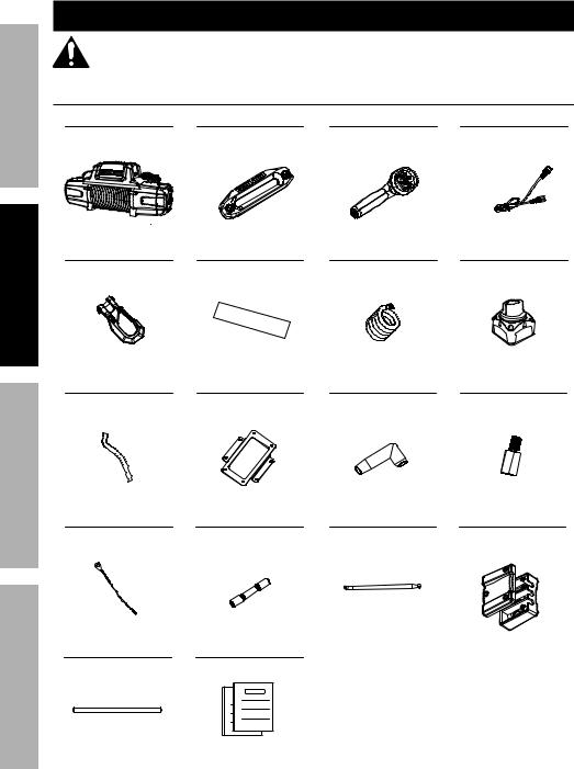
What’s in the Box
Winch x 1 |
Aluminum Fairlead x 1 |
Remote Control x 1 |
Remote Control Cable x 1 |
SeTuP
Hook x 1 |
Rope Protecting Mat x 2 |
Ground Cable x 1 |
Disconnect Switch x 1 |
Red Hook Strap x 1 |
Control Box Baseplate x 1 |
Sheath (red, black, yellow) x 3 |
Extended Copper Screw x 3 |
OPeRATiOn
MAinTenAnCe
Small Black |
Small Black |
Disconnect Switch Cable x 1 |
Terminal Box x 1 |
Wire Extension x 1 |
Wire Connector x 1 |
|
Terminal Box Cover x 1 |
Power Cables |
Instruction Books |
(relocation kit) x 3 |
|
• Manual
• Guide to Winching
Page 6 |
For technical questions, please call 1-888-866-5797. |
Item 56385 |
Mounting the Winch
1.Make sure the Winch will fit the chosen mounting area. If relocating the Control Box is necessary or desired, perform the removal and installation of cables to the Winch before mounting. Refer to Relocating the Control Box on page 8.
2.The mounting plate must be rated to at least the Winch’s capacity.
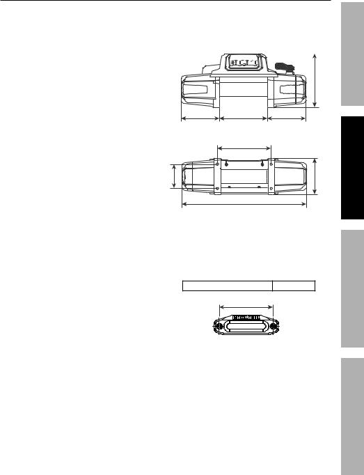
3.Align the Winch perpendicular to center line of the vehicle at the desired location, and mark the locations of the winch base holes. Compare the dimensions of the marked holes to Figure A.
4.Before drilling, verify that the installation surface has no hidden components or structural pieces that will be damaged.
nOTe: This Winch can generate extreme forces. Select a location that can withstand the rated capacity without damage or weakening. Steel reinforcement plates may be needed or a certified welder may need to weld on additional bracing depending on the mounting location.
5.Drill holes appropriate for the hardware at the marked locations.
note: Depending on the vehicle application, it may be beneficial to install the wiring before mounting the Winch. Check all terminal access and plan wiring routes before mounting the Winch.
6.Install the Winch using hardware specified on the specification chart. Tighten fasteners to the following torque values:
Winch mounting fasteners |
30 –33 ft-lb |
|
||||||||||
|
|
|
|
|
|
|
|
|
|
|
|
|
|
|
|
|
|
|
|
|
|
|
|
|
|
|
|
|
|
|
|
|
|
|
|
|
|
|
9.96 in. / 253 mm
7.2 in. / 183 mm |
8.82 in. / 224 mm |
7.2 in. / 183 mm |
|
10 in. / 254 mm |
|
/ 114 mm |
169.5 mm |
4.49 in. |
6.67 in. / |
23.2 in. / 590 mm
Figure A: Winch Dimensions
7.Mount the Fairlead centered on the Winch to guide the Rope onto the Winch drum.
8.Install the Fairlead using hardware specified on the specification chart. Tighten fasteners to the following torque values:
Fairlead mounting fasteners 53 – 57 ft-lb
10 in. / 254 mm
Figure B: Fairlead Mounting Dimensions
SAFeTy
SeTuP
OPeRATiOn
MAinTenAnCe
Item 56385 |
For technical questions, please call 1-888-866-5797. |
Page 7 |
SAFeTy
SeTuP
OPeRATiOn
MAinTenAnCe
Relocating the Control Box (optional)
TO PReVenT SeRiOuS inJuRy FROM eXPLOSiOn Due TO SPARKinG AT THe BATTeRy COnneCTiOn:
unplug the Remote Control Cable and disconnect the Battery Cables before making other wiring connections.
1.Engage the clutch on Winch.
2.Disconnect the vehicle battery cables, negative terminal first.
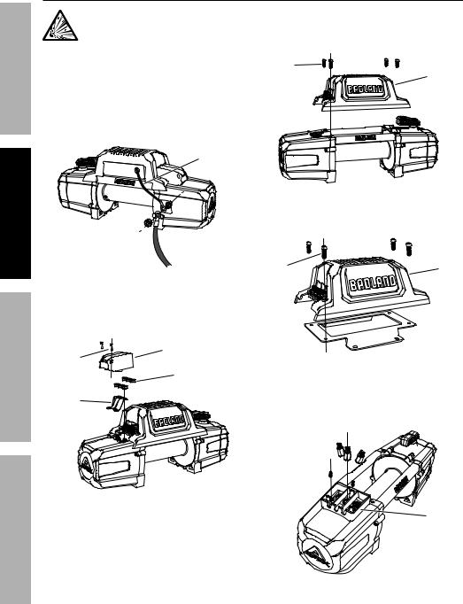
3.Disconnect the Ground Cable and Small Black Wire from terminal on rear of Winch. Make sure the Small Black Wire that connects to the Control Box is disconnected and hanging freely.
Small
Black
Wire
Ground 
Cable
4.Remove the Terminal Cover by unscrewing two
M4 x 16 Screws holding it in place. Remove the six Motor Terminal Nuts and three Copper Plates. Retain all the hardware.
M4 x 16 |
Terminal Cover |
Screw |
Motor |
|
|
|
Terminal |
|
nuts |
Copper |
|
Plates |
|
5.Remove four M6 x 25 Screws holding the Control
Box in place and gently lift it off of the Winch.
M6 x 25 |
|
Screw |
Control |
|
Box |
6.Attach the Control Box Baseplate to the Control Box using the four M6 x 25 Screws removed in step 5.
M6 x 25 |
Control |
|
Screw |
||
Box |
||
|
Control
Box 
Baseplate
7.Install the three Extended Copper Screws to the terminal on the motor. Mount the
Terminal Box on the Winch using two M4 x 12 screws. Do not overtighten screws.
extended Copper 

 Screw
Screw 

M4 x 12

Screw
Terminal
Box
Page 8 |
For technical questions, please call 1-888-866-5797. |
Item 56385 |
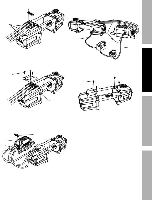
8.Connect three Power Cables (Control Box Relocation Kit) to the Extended Copper Screws on motor terminal using three of the Motor Terminal Nuts removed in step 4.
Motor
Terminal
nuts
Power
9.Install the Terminal Box Cover on the Terminal
Box using three M4.8 x16 Self-Tapping
Screws. Do not overtighten screws.
M4.8 x 16
Screw
Terminal 
Box Cover
Terminal
Box
10.Connect three Power Cables (control box relocation kit) to the Control Box using remaining three Motor Terminal Nuts removed in step 4.
|
Motor |
|
Terminal |
Control |
nuts |
Box |
|
black |
|
red |
|
yellow |
|
11.Use the Small Black Wire Connector and Small Black Wire Extension to lengthen the Small Black Wire from the Control Box.
Reconnect the Ground Cable and Small Black Wire to the backside of the Winch motor.
|
Small Black |
SAFeTy |
|
Wire extension |
|
|
|
|
Black |
Connector |
|
Ground |
|
|
Cable |
|
Red |
|
|
|
|
|
Battery |
|
|
Cable |
12. Install the four decorative M6 x12 |
SeTuP |
|
Screws onto the Winch. |
|
|
M6 x 12 |
|
|
Screw |
|
|
13. |
Place the Control Box on a solid mounting |
OPeRATiOn |
|
||
|
surface in a suitable place near enough to the |
|
|
Winch to allow the cables to be routed properly. |
|
14. |
Verify that the installation surface has no |
|
|
hidden components or structural pieces |
|
|
that will be damaged before drilling. |
|
15. |
Secure the Control Box assembly in place |
|
|
with Baseplate mounting hardware. |
|
|
|
MAinTenAnCe |
Item 56385 |
For technical questions, please call 1-888-866-5797. |
Page 9 |
SAFeTy
SeTuP
OPeRATiOn
MAinTenAnCe
Wiring
TO PReVenT SeRiOuS inJuRy FROM eXPLOSiOn Due TO SPARKinG AT THe BATTeRy COnneCTiOn:
unplug the Remote Control Cable and disconnect the Battery Cables before making other wiring connections.
TO PReVenT SeRiOuS inJuRy FROM LeAKinG BATTeRy ACiD: Do not use a dirty, corroded or leaking battery.
Only use a 12 V automotive (or equivalent) battery, in good condition.
1.Plan a route for the wiring from the point of the vehicle where the Winch will be mounted, or used, to the battery. This route must be secure, out of the way of moving parts, road debris, or any possibility of being damaged by operation or maintenance of the vehicle. For example, you may wish to route the wires under the vehicle, attaching it to the frame using suitable fasteners.
WARninG! Do not attach the wires to the exhaust system, drive shaft, emergency brake cable, fuel line, or any other components which may create damage to the wiring through heat or motion, or create a fire hazard.
2.If you drill through the bumper or any part of the body to route the wires, be sure
to install a rubber grommet in the hole to prevent fraying of the wires at that point.
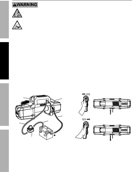
3.Route the Cables from the Winch to the battery, following the precautions discussed above. Refer to Figure C.
6.Attach the red Battery Cable from the Winch to the remaining terminal on the Disconnect Switch.
7.Attach the black Ground Cable and the Small Black Wire to the terminal at the rear of the Winch.
8.Attach the black Ground Cable from the Winch directly to the negative terminal of the battery.
9.Lift the Socket Cover exposing the Remote Control socket and Wireless Receiver Switch. Connect the Remote Control Cable to the socket and the Remote for wired remote control. For wireless control do not use the Remote Control Cable and turn on the Wireless Receiver Switch. Refer to
Remote Control Instructions on page 12.
10.Turn on the Disconnect Switch and operate the remote controls briefly to test Winch function and drum rotation direction. If operation is reversed, the Battery Cables may be connected backwards. Correct any such issue before use.
Socket |
Small |
|
Cover |
Black |
|
|
Wire |
|
|
Black |
in |
|
Ground |
|
|
Cable |
|
Red |
12" |
|
Cable |
|
|
Battery |
|
|
Cable |
|
|
|
Disconnect |
|
|
Switch |
OuT |
|
Figure C: Wiring Connections |
Figure D: Remote Controls |
4. Attach the 12" 2AWG Disconnect Switch Cable |
11. Disconnect and turn off the Remote |
|
to the positive terminal on the battery. |
Control when not in use. |
|
5. Attach the 12" 2AWG Cable from the battery |
12. Turn off the Disconnect Switch when the |
|
to either terminal on the Disconnect Switch. |
Winch is not in use or when the vehicle |
|
|
|
has returned to on-highway operation. |
Page 10 |
For technical questions, please call 1-888-866-5797. |
Item 56385 |
Disconnect Switch
WARninG! Off-highway driving subjects the vehicle and wiring to much higher vibrations than on-highway driving which can cause a breakdown of wiring insulation over time. Use the high current Disconnect Switch included with this Winch to turn OFF the power to the Winch when it is not in use to help reduce the risk of a short circuit.
1. To use the Winch, use the Disconnect Switch |
2. When the Winch is not in use, turn the |
to turn the power to the Winch ON. |
Disconnect Switch OFF to reduce the risk of |
|
a short on the main power to the Winch. |
Preparing the Synthetic Rope
The Synthetic Rope must be properly coiled under tension to be able to support a load without damage.
1.Find a suitable location where the Rope can be spooled onto the Winch while anchored to a solid object. Approximately 70 feet will be required. Alternately, a snatch block (sold separately) may be used to reduce the distance to 35 feet.
2.Move the Clutch Handle to the Freespool position and uncoil the Synthetic Rope until
5 wraps remain on the drum. Move the Clutch Handle back to the Engaged position.
3.Slowly and carefully move the vehicle in reverse to remove slack from the line.
4.Place the vehicle in neutral. Spool the Synthetic Rope back into the Winch while gently applying the brakes. If the ground is flat, shallow
mud or dirt, the brakes can be fully applied. Pavement can generate much higher loads, in which case only light braking is needed.
5.Use a second person to monitor the rope spooling evenly onto the drum.
6.The last layer of Rope can be put on without tension.
SAFeTy
SeTuP
OPeRATiOn
MAinTenAnCe
Item 56385 |
For technical questions, please call 1-888-866-5797. |
Page 11 |
SAFeTy
Remote Control instructions
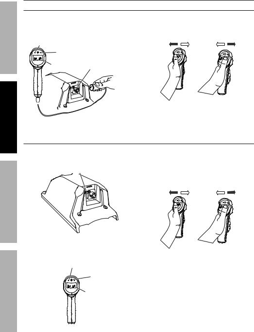
Wired Operation
1. To use the Remote Control in a wired |
3. With the Clutch Handle in the Engaged |
|
configuration, connect the Remote Control Cable |
position, press IN on the Rocker Switch |
|
to the bottom of the Remote Control and to the |
to retract the Synthetic Rope — the red |
|
Remote Control Socket on the Control Box. |
indicator light will flash during winding. |
|
Red indicator Light |
|
|
Blue indicator Light |
|
|
in OuT |
|
|
Rocker |
Remote |
|
Switch |
Control Socket |
|
SeTuP
OPeRATiOn
 Remote
Control Cable
2.The blue indicator light will come on indicating the Remote Control is ready for use.
Wireless Operation
OuT
4.Press OUT on the Rocker Switch to extend the Synthetic Rope out.
1.For wireless Remote Control operation, turn on the Wireless Receiver Switch on the Control Box.
Wireless Receiver
Switch
Control
Box
3.With the Clutch Handle in the Engaged position, press IN on the Rocker Switch to retract the Synthetic Rope — the red indicator light will flash during winding.
4.Press OUT on the Rocker Switch to extend the Synthetic Rope out.
MAinTenAnCe
2.Press and hold the ON/OFF Switch on the Remote for approximately 2 seconds until the red indicator light comes on, indicating the Remote Control is ready for use.
Red indicator Light
On/OFF
Switch
in OuT
Rocker
Switch
OuT
5.To turn off the Remote Control, press and hold the ON/OFF Switch until the red indicator light goes out, approximately 2 seconds.
Turn off the Wireless Receiver Switch.
note: The Remote Control will automatically shut itself off after 2 minutes of inactivity to save the battery.
Page 12 |
For technical questions, please call 1-888-866-5797. |
Item 56385 |
 Loading...