


 Loading...
INSTALLATION GUIDE
AXIS T91A61 Wall Mount
AXIS T91A62 Parapet Mount
AXIS T91A63 Ceiling Mount
AXIS T91A64 Corner Mount
AXIS T91A67 Pole Mount
ÑOLÐëOESPA ITALIANO DEUTSCH AISÐáÇFRAN ENGLISH
About this Document
This document includes instructions for installing the AXIS T91A Mounting Accessories.
Equipment Modifications
This equipment must be installed and used in strict accordance with the instructions given in the user documentation.
Liability
Every care has been taken in the preparation of this document. Please inform your local Axis office of any inaccuracies or omissions. Axis Communications AB cannot be held responsible for any technical or typographical errors and reserves the right to make changes to the product and documentation without prior notice. Axis Communications AB makes no warranty of any kind with regard to the material contained within this document, including, but not limited to, the implied warranties of merchantability and fitness for a particular purpose. Axis Communications AB shall not be liable nor responsible for incidental or consequential damages in connection with the furnishing, performance or use of this material.
Support
Should you require any technical assistance, please contact your Axis reseller. If your questions cannot be answered immediately, your reseller will forward your queries through the appropriate channels to ensure a rapid response. If you are connected to the Internet, you can:
•find answers to resolved problems in the FAQ database. Search by product, category, or phrases
•report problems to Axis support by logging in to your private support area.

AXIS T91A Series Installation Guide |
Page 3 |
AXIS T91A Mounting Accessories
This installation guide provides instructions for installing the wall/parapet/ceiling/corner/pole mounting accessories for Axis network cameras. For all other aspects of using the Axis network camera, please see the Installation Guide and User’s Manual, available from www.axis.com
Installation steps
1.Check the package contents against the list below
2.Hardware overview. See page 4
3.Install the hardware:
•Install the AXIS T91A61 Wall Mount, see page 6
•Install the AXIS T91A62 Parapet Mount, see page 7
•Install the AXIS T91A63 Ceiling Mount, see page 9
•Install the AXIS T91A64 Corner Mount, see page 11
•Install the AXIS T91A67 Pole Mount, see page 12
Important!
This product must be used in compliance with local laws and regulations.
 Package contents
Model |
Item |
|
|
AXIS T91A61 Wall Mount |
Wall bracket |
|
Bracket holder |
|
|
AXIS T91A62 Parapet Mount |
Parapet bracket |
|
Bracket holder |
|
|
AXIS T91A63 Ceiling Mount |
Ceiling bracket |
|
Bracket holder |
|
|
AXIS T91A64 Corner Mount |
Corner bracket (AXIS T91A61 required) |
|
4 M8x22 screws |
|
|
AXIS T91A67 Pole Mount |
Pole bracket |
|
Steel straps (steel strap tool not supplied) |
|
|
ENGLISH
Page 4 |
AXIS T91A Series Installation Guide |
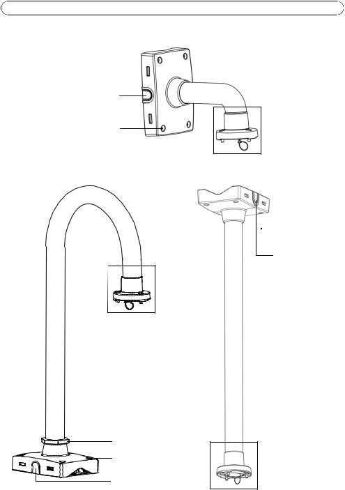
 Hardware overview
Side cover (remove for cable)
Torx T30 screws (4)
Pendant adapter
Parapet bracket |
Ceiling bracket |
Pendant adapter |
 Torx T30
screws (4)
Side cover (remove for cable)
Secure nut |
|
Torx T30 screws (4) |
|
Side cover |
|
(remove for cable) |
Pendant adapter |
|

AXIS T91A Series Installation Guide |
Page 5 |
Corner mount bracket |
Pole bracket |
Screw hole (top) |
|
|
Mounted |
|
|
|
|
|
|
|
|
|
|
|
|
|
|
|
|
|
|
|
|
|
|
||
|
this way up |
|
|
|
|
|
|
|
|
|
|
|
|
|
|
|
|
|
|
|
|
|
|
|
|
|
|
|
|
|
|
|
|
|
||||
|
Steel straps |
|
|
|
|
|
|
|||||
|
Pendant adapter |
|||||||||||
|
(requires steel strap |
|||||||||||
|
|
|
|
|
|
|
||||||
|
tool - not supplied) |
|
|
|
|
|
|
|||||
Pendant adapter |
Bracket holder |
|
|
|
|
|
|
|||||
|
|
|
|
|
|
|
|
|
|
|
Locking tab |
|
|
|
|
|
|
|
|
|
|
||||
|
|
|
|
|
|
|
|
|
|
|
Holes for |
|
|
|
|
|
|
|
|
|
|
|
|
||
|
|
|
|
|
|
|
|
|
||||
|
|
|
|
|
|
|
|
|
|
|||
|
|
|
|
|
|
|
|
|
|
|
mounting |
|
|
|
|
|
|
|
|
|
|
|
|
screws (6) |
|
|
This way up |
|
|
|
|
|
|
|||||
|
|
|
|
|
|
|
|
|
|
|
||
|
(when mounting |
|
|
|
|
|
|
|
|
|
|
|
|
on wall) |
|
|
|
|
|
|
|
|
Metal tabs |
||
|
|
|
|
|
|
|
|
|
||||
|
|
|
|
|
|
|
|
|
|
|
for temporary |
|
|
|
|
|
|
|
|
|
|
|
|
support (4) |
|
|
|
|
|
|
|
|
|
|
|
|
|
|
Torx T30 screws (3)
Stop screw
Safety wire
Slots for
unit holders (3)
Note:
Some installations may require the supplied pendant adapter to be replaced which is done by loosening the stop screw and unscrewing the adapter. In this case, refer to the Installation Guide included with the pendant kit.
ENGLISH
Page 6 |
AXIS T91A Series Installation Guide |
 Install the Hardware
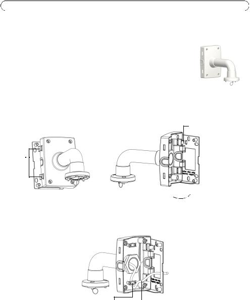
Install the AXIS T91A61 Wall Mount
1.Refer to Hardware overview, on page 4 for information on the supplied parts.
2.Route the network cable through or along the wall.
3.Attach the bracket holder in the desired position using screws that are appropriate for the wall material and the weight of the camera and bracket.
4.The wall bracket can temporarily be hooked on the bracket holder, in order to easily route the cable through the bracket:
Tabs
Slide bracket between the tabs on the bracket holder
Locking tab
Swing wall bracket  to the side for temporary support
5. Route the necessary cables through the wall bracket, securing them in the cable holder.
Cable Cable holder
6.Pull the locking tab and unhook the wall bracket from the temporary position.
7.Use the Torx screws to secure the wall bracket to the bracket holder.
8.Refer to the Installation Guide for the network camera for instructions on how to attach the camera to the bracket.
AXIS T91A Series Installation Guide |
Page 7 |
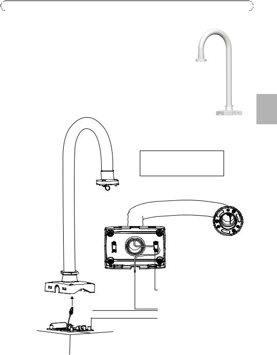
Install the AXIS T91A62 Parapet Mount
1.Refer to Hardware overview, on page 4 for information on the supplied parts.
2.Route the network cable through or along the roof.
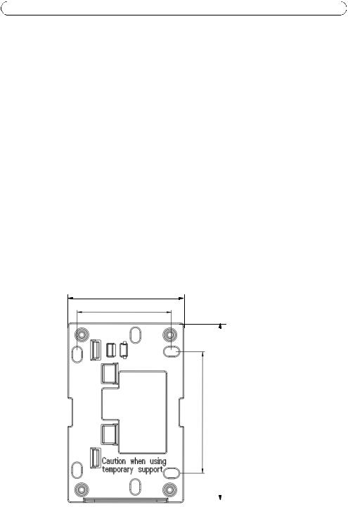
3.Attach the bracket holder in the desired position on the roof using screws that are appropriate for the material and the weight of the camera and bracket. Install the bracket maximum 80 mm (3.2 in.) from the edge of the roof for the camera’s outer diameter to be aligned with the edge of the roof. Maximum weight allowed 15 kg (33 lbs).
4.Route the necessary cables through the parapet bracket, securing them in the cable holder.
Note: Do not use bracket holder as a temporary support with the parapet bracket.
Cable holder
Cable
Bracket holder
Install bracket holder max. 80 mm (3.2 in.) from the edge of the roof
ENGLISH
Page 8 |
AXIS T91A Series Installation Guide |
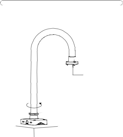
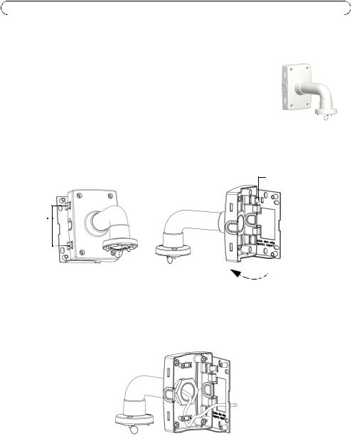
5.Use the Torx screws to secure the parapet bracket to the bracket holder.
6.Rotate the bracket and tighten the secure nut to lock the bracket in a sideways position. The camera can now be installed safely rather than hanging over the edge of the roof. The secure nut is loose at delivery for this purpose.
 Torx T30 screws (3)
 Slots for unit holders (3)
Safety wire
Rotate sideways to install camera
 Secure nut
 Torx T30 screws (4)
7.Refer to the Installation Guide for the network camera for instructions on how to attach the camera to the bracket.
8.Rotate the bracket into position and tighten the secure nut firmly.
Notes:
•Some installations may require the supplied pendant adapter to be replaced, which is done by loosening the stop screw and unscrewing the adapter. In this case, refer to the Installation Guide included with the pendant kit.

AXIS T91A Series Installation Guide |
Page 9 |
Install the AXIS T91A63 Ceiling Mount
1.Refer to Hardware overview, on page 4 and page 5 for information on the supplied parts.
2.Route the network cable through or along the ceiling.
3.Attach the bracket holder in the desired position in the ceiling using screws that are appropriate for the ceiling material and the weight of the camera and bracket. Maximum weight allowed 15kg (33lbs).
ENGLISH
Note: Do not use bracket holder as a temporary support with the ceiling bracket.
4. Route the necessary cables through the ceiling bracket, securing them in the cable holder.

Page 10 |
AXIS T91A Series Installation Guide |
5. Use the Torx screws to secure the ceiling bracket to the bracket holder.
Torx screws(4) 


6.Refer to the Installation Guide for the network camera for instructions on how to attach the camera to the bracket.
AXIS T91A Series Installation Guide |
Page 11 |
Install the AXIS T91A64 Corner Mount
1.Refer to Hardware overview, on page 4 for information on the supplied parts.
2.Attach the corner bracket in the desired position using screws that are appropriate for the wall material and the weight of the camera and bracket.
3.Attach the bracket holder (not included) to the corner bracket using the supplied screws.
4.The wall bracket (not included) can temporarily be hooked on the bracket holder, in order to easily route the cable through the bracket:
Bracket |
Tabs |
|
holder |
Wall bracket |
Locking tab |
|
||
|
Corner bracket |
|
Slide bracket between the |
Swing wall bracket |
|
tabs on the bracket holder |
||
to the side for |
||
|
||
|
temporary support |
Note:
The bracket holder and wall bracket (AXIS T91A61) are required for the installation but must be purchased separately, see the table in Package contents, on page 3.
5. Route the necessary cables through the wall bracket, securing them in the cable holder.
ENGLISH
Cable Cable holder
6.Press the locking tab and unhook the wall bracket from the temporary position.
7.Use the Torx screws to secure the wall bracket to the bracket holder.
8.Refer to the Installation Guide for the network camera for instructions on how to attach the camera to the bracket.

Page 12 |
AXIS T91A Series Installation Guide |
Install the AXIS T91A67 Pole Mount
1.Refer to Hardware overview, on page 4 and page 5 for information on the supplied parts.
2.Route the necessary cables through the bracket, securing them with the cable holder.
3.Use the supplied steel straps to attach the bracket to the pole and tighten with a steel strap tool (not supplied).
Cable holder
Pole mount
Steel straps
Cable Cable holder
4.Refer to the Installation Guide for the network camera for instructions on how to attach the camera to the bracket.
AXIS T91A Series Installation Guide Page 13
Technical Data
|
AXIS T91A61 |
AXIS T91A62 |
AXIS T91A63 |
AXIS T91A64 |
AXIS T91A67 |
|
|
|
|
Wall Mount |
Parapet Mount |
Ceiling Mount |
Corner Mount |
Pole Mount |
|
|
|
|
|
|
|
|
|
|
|
|
Size |
140 x 200 x 270 |
470 x 754 x 138 |
195 x 750 x 138 |
345 x 200 x 185 |
140 x 200 x 270 |
|
|
|
W x H x D |
(5.6 x 8 x 10.7) |
(18.5 x 29.7 x 5.4) |
(7.7 x 29.5 x 5.4) |
(13.6 x 8 x 7.3) |
(5.6 x 8 x 10.7) |
|
|
|
mm (in.) |
|
|
|
|
|
|
|
|
|
|
|
|
|
|
|
|
|
Weight g (lbs) |
1450 (3.2) |
2900 (6.4) |
2000 (4.4) |
1250 (2.8) |
1220 (2.7) |
|
|
|
|
|
|
|
|
|
|
|
|
Max. weight |
15 (33) |
15 (33) |
15 (33) |
15 (33) |
15 (33) |
|
|
|
ENGLISH |
||||||||
supported |
|
|
|
|
|
|
||
|
|
|
|
|
|
|
||
kg (lbs) |
|
|
|
|
|
|
|
|
|
|
|
|
|
|
|
|
|
Material |
Aluminum |
Aluminum |
Aluminum |
Aluminum |
Aluminum |
|
|
|
|
|
|
|
|
|
|
|
|
Color code |
NCS S 1002-B |
NCS S 1002-B |
NCS S 1002-B |
NCS S 1002-B |
NCS S 1002-B |
|
|
|
|
|
|
|
|
|
|
|
|
Mounting |
9 (0.35) |
9 (0.35) |
9 (0.35) |
10 (0.4) |
- |
|
|
|
holes diameter |
|
|
|
|
|
|
|
|
mm (in.) |
|
|
|
|
|
|
|
|
|
|
|
|
|
|
|
|
|
Pole size |
- |
|
- |
- |
80–150 (3–6) |
|
|
|
mm (in.) |
|
|
|
|
|
|
|
|
|
|
|
|
|
|
|
|
Bracket holder
118 mm (4.6 in.)
96 mm (3.8 in.)
9.(4 mm 124 |
2.(7 mm 183 |
|
).in |
).in |
|
|
|
|
|
|
|

AXIS T91A Guide d'installation |
Page 15 |
Accessoires de montage AXIS T91A
Ce guide d’installation vous explique comment installer les accessoires de montage mural, de montage d’angle et de montage sur poteau pour les caméras réseau Axis. Pour toute autre instruction d’utilisation de la caméra réseau Axis, veuillez consulter le guide d’installation et le manuel de l’utilisateur, disponibles sur le site www.axis.com
Procédure d'installation
1.Vérification du contenu de l’emballage par rapport à la liste ci-dessous
2.Vue d’ensemble du matériel. Reportez-vous à la page 16.
3.Installation du matériel :
•Installation du montage mural AXIS T91A61, voir page 18
Important !
Ce produit doit être utilisé conformément aux lois et dispositions locales en vigueur.
•Installation du montage sur parapet AXIS T91A62, voir page 19
•Installation de la fixation au plafond AXIS T91A63, voir page 21
•Installation du montage d’angle AXIS T91A64, voir page 23
•Installation du montage sur poteau AXIS T91A67, voir page 24
 Contenu de l’emballage
Modèle |
Élément |
|
|
Montage mural AXIS T91A61 |
Support mural |
|
Dispositif de fixation du support |
|
|
Montage de parapet AXIS T91A62 |
Support de parapet |
|
Dispositif de fixation du support |
|
|
Montage au plafond AXIS T91A63 |
Support pour installation au plafond |
|
Dispositif de fixation du support |
|
|
Montage d'angle AXIS T91A64 |
Support d’angle (AXIS T91A61 requis) |
|
4 vis M8x22 |
|
|
Montage sur poteau AXIS T91A67 |
Support de montage sur poteau |
|
Bandes en acier (outil de fixation des bandes en acier non fourni) |
|
|
AISÇFRAN

Page 16 |
AXIS T91A Guide d'installation |
 Description du matériel
Couvercle latéral (retirer pour passer le câble)
Vis Torx T30 (4)
Adaptateur de suspension
Support de parapet |
Support pour installation au plafond |
Adaptateur de suspension |
 Torx T30
vis (4)
Couvercle latéral (retirer pour passer le câble)


 Écrou de sécurité


 Vis Torx T30 (4)
Couvercle latéral
(retirer pour passer le câble) Adaptateur de suspension

AXIS T91A Guide d'installation |
Page 17 |
Support de montage d’angle |
Support de montage sur poteau |
|
Trou pour les vis |
|
(partie supérieure) |
Monté |
|
|
||
|
|
|||
dans ce sens |
|
|
|
|
|
|
|
|
|
(vers le haut) |
|
|
|
|
Bandes en |
|
acier |
|
|
|
|
|
||
|
|
Adaptateur |
||
(nécessitent un outil de fixation |
|
|||
|
de suspension |
|||
outil : non fourni) |
|
|||
|
|
|||
Adaptateur de suspension
Dans ce sens (vers le haut)
(lors du montage mural)
Vis Torx T30 (3)
Vis de butée
Fil de sécurité
Logements pour
les supports de rack (3)
Dispositif de fixation du support
Patte de blocage
Trous pour les vis de montage (6)
Pattes en métal pour un support (4)
Remarque :
Certaines installations peuvent nécessiter le remplacement de l’adaptateur de suspension. Pour ce faire, desserrez la vis de butée et dévissez l'adaptateur. Le cas échéant, reportezvous au Guide d’installation fourni avec l’adaptateur de suspension.
AISÇFRAN
Page 18 |
AXIS T91A Guide d'installation |
 Installation du Matériel
Installation de Montage mural AXIS T91A61
1.Reportez-vous à la section Description du matériel, à la page 16 pour obtenir des informations sur les pièces fournies.
2.Acheminez le câble réseau à travers ou le long du mur.
3.Fixez le dispositif de fixation du support dans la position souhaitée en utilisant des vis qui sont appropriées au matériau mural et au poids de la caméra et du support.
4.Le support mural peut être temporairement accroché sur le dispositif de fixation du support, afin d'acheminer facilement le câble dans le support :
Pattes 
Glisser le support entre
les pattes sur le dispositif de fixation du support
Patte de blocage
Faire pivoter le support mural vers le côté
pour obtenir un support temporaire
5.Faites passer les câbles nécessaires dans le support mural en le fixant dans le dispositif de support du câble.
|
|
|
|
|
|
|
|
|
|
|
|
Attache |
Attache |
||
du câble |
|
|
|
6.Tirez la patte de blocage et décrochez le support mural de la position temporaire.
7.Utilisez les vis Torx pour fixer le support mural au dispositif de fixation du support.
8.Reportez-vous au guide d’installation de la caméra réseau pour savoir comment fixer la caméra au support.

AXIS T91A Guide d'installation |
Page 19 |
Installation de Montage de parapet AXIS T91A62
1.Reportez-vous à la section Description du matériel, à la page 16 pour obtenir des informations sur les pièces fournies.
2.Acheminez le câble réseau à travers ou le long du toit.
3.Fixez le dispositif de fixation du support dans la position souhaitée sur le toit en utilisant des vis qui sont appropriées au matériau mural et au poids de la caméra et du support. Installez le support à 80 mm maximum (3.2 po.) du bord du toit pour que le diamètre extérieur de la caméra s'aligne avec le bord du toit. Poids maximum autorisé 15 kg (33 livres).
4.Faites passer les câbles nécessaires dans le support de parapet en le fixant dans le dispositif de support du câble.
AISÇFRAN
Remarque : ne pas utiliser le dispositif de fixation du support
comme support temporaire avec le support de parapet.
Dispositif de support du câble
Attache
Dispositif de fixation du support
Installation du dispositif de fixation du support 80 mm max. (3,2 po.)
du bord du toit

Page 20 |
AXIS T91A Guide d'installation |
5.Utilisez les vis Torx pour fixer le support du parapet au dispositif de fixation du support.
6.Faites tourner le support et serrez l'écrou de sécurité pour bloquer le support dans une position latérale. La caméra peut maintenant être installée en toute sécurité au lieu d'être suspendue sur le bord du toit. C'est pourquoi l'écrou de sécurité est desserré à la livraison.
 Vis Torx T30 (3)
 Supports de rack (3)
Fil de sécurité
Faites tourner latéralement pour installer la caméra
 Écrou de sécurité
 Vis Torx T30 (4)
7.Reportez-vous au guide d’installation de la caméra réseau pour savoir comment fixer la caméra au support.
8.Faites tourner le support dans la position et serrez bien l'écrou de sécurité.
Remarques :
•Certaines installations peuvent nécessiter le remplacement de l’adaptateur de suspension. Pour ce faire, desserrez la vis de butée et dévissez l'adaptateur. Le cas échéant, reportez-vous au Guide d’installation fourni avec l’adaptateur de suspension.
Loading...