


 Loading...
INSTALLATION GUIDE
AXIS P13-E Network Camera Series
AXIS P1343-E Network Camera
AXIS P1344-E Network Camera
AXIS P1346-E Network Camera
AXIS P1347-E Network Camera
ESPAÑOL ITALIANO DEUTSCH FRANÇAIS ENGLISH

Legal Considerations
Video and audio surveillance can be prohibited by laws that vary from country to country. Check the laws in your local region before using this product for surveillance purposes. This product includes one (1) H.264 decoder license and (1) AAC decoder license. To purchase further licenses, contact your reseller.
Trademark Acknowledgments
Apple, Boa, Bonjour, Ethernet, Internet Explorer, Linux, Microsoft, Mozilla, Netscape Navigator, OS/2, Real, SMPTE, QuickTime, UNIX, Windows, WWW are registered trademarks of the respective holders. Java and all Java-based trademarks and logos are trademarks or registered trademarks of Sun Microsystems, Inc. in the United States and other countries. Axis Communications AB is independent of Sun Microsystems Inc. UPnP™ is a certification mark of the UPnP™ Implementers Corporation.
Safety
This product complies to EN/IEC 60950-1 and EN/IEC 60950-22, Safety of Information Technology Equipment.
Electromagnetic Compatibility (EMC)
This equipment has been designed and tested to fulfill applicable standards for:
•Radio frequency emission when installed according to the instructions and used in its intended environment.
•Immunity to electrical and electromagnetic phenomena when installed according to the instructions and used in its intended environment.
USA - This equipment has been tested using a shielded network cable (STP) and found to comply with the limits for a Class B digital device, pursuant to part 15 of the FCC Rules. These limits are designed to provide reasonable protection against harmful interference in a residential installation. This equipment generates, uses and can radiate radio frequency energy and, if not installed and used in accordance with the instructions, may cause harmful interference to radio communications. However, there is no guarantee that interference will not occur in a particular installation. If this equipment does cause harmful interference to radio or television reception, which can be determined by turning the equipment off and on, the user is encouraged to try to correct the interference by one or more of the following measures:
•Reorient or relocate the receiving antenna.
•Increase the separation between the equipment and receiver.
•Connect the equipment into an outlet on a circuit different from that to which the receiver is connected.
Canada - This Class B digital apparatus complies with Canadian ICES-003.
Europe - This digital equipment fulfills the requirements for radiated emission according to limit B of EN55022, and the requirements for immunity according to EN55024 residential and commercial industry.
Australia - This electronic device meets the requirements of the Radio communications (Electromagnetic Compatibility) Standard AS/NZS CISPR22:2002.
Japan - B
Korea - |
|
% |
|
|
|
|
|
|
|
|
|
|
|
|
|
|
|
|
|
|
Equipment Modifications
This equipment must be installed and used in strict accordance with the instructions given in the user documentation. This equipment contains no user-serviceable components. Unauthorized equipment changes or modifications will invalidate all applicable regulatory certifications and approvals.
Liability
Every care has been taken in the preparation of this document. Please inform your local Axis office of any inaccuracies or omissions. Axis Communications AB cannot be held responsible for any technical or typographical errors and reserves the right to make changes to the product and documentation without prior notice. Axis Communications AB makes no warranty of any kind with regard to the material contained within this document, including, but not limited to, the implied warranties of merchantability and fitness for a particular purpose. Axis Communications AB shall not be liable nor responsible for incidental or consequential damages in connection with the furnishing, performance or use of this material. This product is only to be used for its intended purpose.
RoHS
This product complies with the European RoHS directive, 2002/95/EC.
WEEE Directive
The European Union has enacted a Directive 2002/96/EC on Waste Electrical and Electronic Equipment (WEEE Directive). This directive is applicable in the European Union member states. The WEEE marking on this product (see right) or
its documentation indicates that the product must not be disposed of together with household waste. To prevent possible harm to human health and/or the environment, the product must be disposed of in an approved and environmentally safe recycling process. For further information on how to dispose of this product correctly, contact the product supplier, or the local authority responsible for waste disposal in your area.
Business users should contact the product supplier for information on how to dispose of this product correctly. This product should not be mixed with other commercial waste.
Support
Should you require any technical assistance, please contact your Axis reseller. If your questions cannot be answered immediately, your reseller will forward your queries through the appropriate channels to ensure a rapid response. If you are connected to the Internet, you can:
•download user documentation and firmware updates
•find answers to resolved problems in the FAQ database. Search by product, category, or phrases
•report problems to Axis support by logging in to your private support area.

Safeguards
Please read through this Installation Guide carefully before installing the Axis product. Keep the Installation Guide for further reference.
|
|
|
|
• Store the Axis product in a dry and ventilated environment. |
|
||
• Avoid exposing the Axis product to vibration, shocks or heavy pressure. Do not install the |
|
||
|
product on unstable brackets, unstable or vibrating surfaces or walls, since this could cause |
|
|
|
damage to the product. |
|
|
• Only use applicable tools when installing the Axis product; excessive force could cause |
ENGLISH |
||
|
damage to the product. |
||
|
|
||
• Do not use chemicals, caustic agents, or aerosol cleaners. Use a damp cloth for cleaning. |
|
||
• Use only accessories that comply with technical specification of the product. These can be |
|
||
|
|||
|
provided by Axis or a third party. |
|
|
• Use only spare parts provided by or recommended by Axis. |
|
||
• Do not attempt to repair the product by yourself, contact Axis or your Axis reseller for ser- |
|
||
|
vice matters. |
|
|
|
|
||
|
|
|
|
• This Axis product shall be used in compliance with local laws and regulations. |
|
||
Transportation
•When transporting the Axis product, use the original packaging or equivalent to prevent damage to the product.

Battery Replacement
This Axis product uses a 3.0 V CR2032 lithium battery as the power supply for its internal real-time clock (RTC). Under normal conditions this battery will last for a minimum of 5 years. Low battery power affects the operation of the RTC, causing it to reset at every power-up. A log message will appear when the battery needs replacing. The battery should not be replaced unless required!
If the battery does need replacing, please contact www.axis.com/techsup for assistance.
•Dispose of used batteries according to the manufacturer's instructions.
•Risk of explosion if battery is incorrectly replaced.
•Replace only with the same or equivalent battery, as recommended by the manufacturer.

AXIS P13-E Network Camera Series Installation Guide |
Page 5 |
AXIS P1343-E, AXIS P1344-E AXIS P1346-E & AXIS P1347-E Installation Guide
This installation guide provides instructions for installing an AXIS P1343-E/P1344-E/P1346-E/ P1347-E Network Camera on your network. For all other aspects of using the product, please see the User’s Manual, available on the CD included in this package, or from www.axis.com
Installation steps
1.Check the package contents against the list below.
2.Install the hardware. See page 8.
3.Assign an IP address. See page 13.
4.Set the password. See page 16.
5.Adjust zoom and focus. See page 19.
Important!
This product must be used in compliance with local laws and regulations.
 Package contents
Item |
Models/variants/notes |
|
|
Network camera |
AXIS P1343-E/AXIS P1344-E/AXIS P1346-E/AXIS P1347-E |
|
|
Wall bracket |
Wall bracket with internal cable channel |
|
|
Tools |
Torx T20 screwdriver |
|
Allen key |
|
|
CD |
AXIS Network Video Product CD, including product documentation, installation |
|
tools and other software |
|
|
Printed Materials |
AXIS P13-E Network Camera Series Installation Guide (this document) |
|
Drill template |
|
Axis Warranty Document |
|
Extra serial number label (2x) |
|
AVHS Authentication key |
|
|
|
|
Optional accessories |
See www.axis.com for information on available accessories |
|
|
ENGLISH
Page 6 |
AXIS P13-E Network Camera Series Installation Guide |
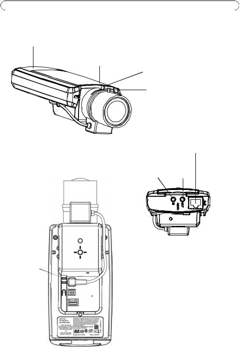
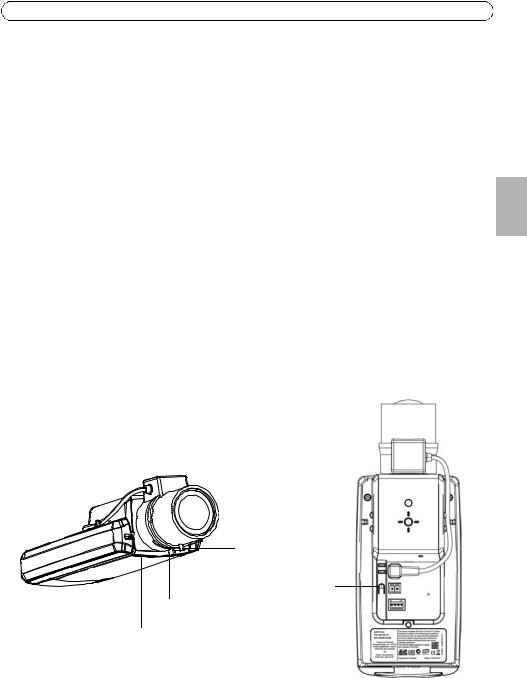
 Hardware overview
SD memory card slot
Status LED
Zoom puller
Focus puller
Rear view
Audio in
Bottom view
Network connector |
(PoE) |
Audio out |
Power LED |
|
|
|
|
|
|
||
Network LED |
|
|
|
|
|
|
|
Iris connector |
|
|
|
|
|
|
|
||
Control button |
|
|
|
|
|
|
Power connector |
|
|
|
|
|
|
|
|||
|
|
|
|
|
|
|
|
|
|
|
|
|
|
|
|
|
I/O terminal connector |
|
|
|
|
|
|
|
|
|
|
|
|
|
|
|
|
|
Product number (P/N) & |
|
|
|
|
|
|
|
|
Serial number (S/N) |
Example image: AXIS P1343-E
AXIS P13-E Network Camera Series Installation Guide |
Page 7 |
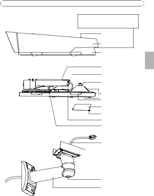
Part number (P/N) & Serial number (S/N). |
|
The serial number may be required |
|
during the installation. |
|
Sunshield adjustment |
|
screw (2x) |
|
Sunshield |
|
Top cover |
|
Network camera |
|
Network connector |
|
Safety wire tab |
|
Cable holes
Bottom cover screws (4x) |
Cable cover |
Cable cover screws (2x) |
Bottom cover |
Heaters Caution!
May be hot
Network cable (route through wall bracket)
 Bracket adapter
 Bracket screws (4x)
Bracket adjustment screw
Wall bracket
ENGLISH
Example image: AXIS P1343-E

Page 8 |
AXIS P13-E Network Camera Series Installation Guide |
 Install the hardware
The instructions below describe the installation of AXIS P1343-E/P1344-E/P1346-E/P1347-E.
Install the wall bracket
1.Use the supplied drill template to prepare a wall, ceiling, or pole for installation of the wall bracket.
2.Route the network cable through the wall bracket and the bracket adapter. Leave approximately 30 cm (11.8”) of cable for connecting the camera.
3.Install the wall bracket on a wall, ceiling, or pole and make sure that the screws and plugs are appropriate for the material (e.g. wood, metal, sheet rock, stone).
Notes:
• The weight of the camera is shown in the table below. Check that the material is strong enough to support this weight.
Model |
Weight |
|
|
AXIS P1343-E |
3090 g (6.8 lb.) |
|
|
AXIS P1344-E |
3120 g (6.9 lb.) |
|
|
AXIS P1346-E |
3130 g (6.9 lb.) |
|
|
AXIS P1347-E |
3.200 g (7.2lb.) |
• For more technical specifications, please see the User’s Manual, available on the CD included in this package, or from www.axis.com
AXIS P13-E Network Camera Series Installation Guide |
Page 9 |
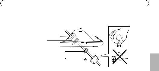
Route the network cable through the cable hole
1. Loosen the cable cover screws; detach the cable cover from the bottom cover.


 Cable
Cable glan
glan d
d
Gasket
Plug (discard)

Cap 

2.Remove the cap, the plug and the gasket from the cable gland that is to be used.
3.Route the network cable through the cap.
4.Slide the network cable through the slit on the gasket to attach the gasket to the network cable. See Unit connectors, on page 22 for information on network cable requirements.
5.Route the network cable through the cable gland.
6.Press the gasket into the cable gland and screw the cap on firmly.
Note:
Using any other than the provided cable gland may cause water to seep in and damage the product. Cables must have a diameter of 4.0 mm - 5.5 mm.
ENGLISH
Page 10 |
AXIS P13-E Network Camera Series Installation Guide |
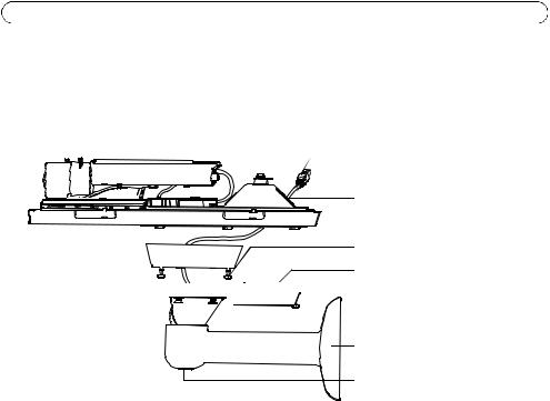
Install the camera on the bracket
1.Install the camera with the bottom cover on the bracket and tighten the bracket screws.
2.Remove the gasket from one of the holes in the bottom cover, see illustration on page 11.
3.Route the cable through the hole and attach the cable gasket to the hole.
 Network cable (route
through wall bracket)
Cable holes
Bracket screw (4x)
Cable cover


 Cable cover screw (2x)
Wall bracket
Bracket adjustment screw
4.Connect the cables, see Connect the cables, on page 11.
5.Loosen the bracket adjustment screw to aim the camera to the point of interest and focus the camera according to the instructions under Adjust zoom and focus, on page 19. See Access the video stream, on page 18 for information on how to view the video stream.
6.Take the top cover and attach the safety wire to the tab on the bottom cover.
7.Install the top cover. Make sure to tighten diagonally opposite bottom cover screws a few turns at a time until all are tight. This will help ensure that the bottom cover gasket is compressed evenly. Do not attempt to tighten the screws completely the first time.
8.Install the cable cover and tighten the cable cover screws.
9.Loosen the sun screen adjustment screws and adjust the sunshield to the front position.
AXIS P13-E Network Camera Series Installation Guide Page 11
Connect the cables
1. |
Optionally insert an SD memory card (not included) into the SDHC (Secure Digital High |
|
|
Capacity) card slot. A standard or high capacity SD card is required to store images locally in |
|
|
the camera. |
|
2. |
Optionally connect external input/output devices. See page 23 for information on the terminal |
|
|
connector pins. Prepare the cables with gaskets, see Route the network cable through the cable |
|
|
hole, on page 9, and route the cables through the cable holes into the bottom cover and to the |
|
|
camera. |
|
3. |
Connect the camera to the network using a shielded network cable. Connect the network cable |
ENGLISH |
|
to the network connector on the bottom. The network cable and the I/O cable between the |
|
|
|
bottom cover and the camera are already connected at delivery
Network cables
I/O cable |
Bottom cover
Network connector (PoE OUT,
connected at delivery)

 Cable holes

 Network connector (PoE IN)
LED indicator
Cold Startup Delay switch
(enabling not required - see text below)
Alarm output (connected at delivery)
4.Check that the indicator LEDs indicate the correct conditions. See the table on page 25 for further details. Note that the Status LED can be configured to be unlit during normal operation.

Page 12 |
AXIS P13-E Network Camera Series Installation Guide |
Cold Startup Delay Switch
The housing used in this Axis product features Arctic Temperature Control, which is enabled by setting the Cold Startup Delay switch to I (ON). When enabled, this function controls when the camera restarts after a power cut, when temperatures are below 0 °C (32 °F); the camera is first heated to approximately 0 °C (32 °F) before it initializes. This prevents damage to camera models that include moving parts. Since this camera does not require this function, it is disabled by default.
AXIS P13-E Network Camera Series Installation Guide |
Page 13 |
 Assign an IP address
Most networks today have a DHCP server that automatically assigns IP addresses to connected devices. If your network does not have a DHCP server the network camera will use 192.168.0.90 as the default IP address.
If you would like to assign a static IP address, the recommended method in Windows is either AXIS IP Utility or AXIS Camera Management. Depending on the number of cameras you wish to install, use the method that best suits your purpose.
Both of these free applications are available on the AXIS Network Video Product CD supplied with this product, or they can be downloaded from www.axis.com/techsup
Method |
Recommended for |
Operating system |
|
|
|
AXIS IP Utility |
Single camera |
Windows |
See page 14 |
Small installations |
|
|
|
|
AXIS Camera Management |
Multiple cameras |
Windows 2000 |
See page 15 |
Large installations |
Windows XP Pro |
|
Installation on a different subnet |
Windows 2003 Server |
|
|
Windows Vista |
|
|
Windows 7 |
|
|
|
Notes:
•If assigning the IP address fails, check that there is no firewall blocking the operation.
•For other methods of assigning or discovering the IP address, e.g. in other operating systems, see page 21.
ENGLISH
Page 14 |
AXIS P13-E Network Camera Series Installation Guide |
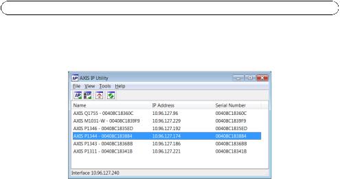
AXIS IP Utility - single camera/small installation
AXIS IP Utility automatically discovers and displays Axis devices on your network. The application can also be used to manually assign a static IP address.
Note that the computer running AXIS IP Utility must be on the same network segment (physical subnet) as the network camera.
Automatic discovery
1.Check that the network camera is connected to the network and that power has been applied.
2.Start AXIS IP Utility.
3.When the network camera appears in the window, double-click to open its home page.
4.See page 16 for instructions on how to assign the password.
Set the IP address manually (optional)
1.Acquire an unused IP address on the same network segment as your computer.
2.Select the network camera in the list.
3.Click the Assign new IP address to selected device button  and enter the IP address.
4.Click Assign and follow the on-screen instructions. Note that the camera must be restarted within 2 minutes for the new IP address to be set.
5.Click Home Page to access the camera’s web pages.
6.See page 16 for instructions on how to set the password.
AXIS P13-E Network Camera Series Installation Guide |
Page 15 |
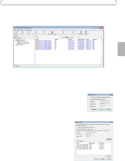
AXIS Camera Management - multiple cameras/large installations
AXIS Camera Management can automatically discover multiple Axis devices, show connection status, manage firmware upgrades and set IP addresses.
ENGLISH
Automatic discovery
1.Check that the camera is connected to the network and that power has been applied.
2.Start AXIS Camera Management. When the network camera appears in the window, right-click the link and select Live View Home Page.
3.See page 16 for instructions on how to set the password.
Assign an IP address in a single device
1. Select the network camera in AXIS Camera Management and click the Assign IP button  .
.
2.Select Assign the following IP address and enter the IP address, the subnet mask and default router the device will use.
3.Click OK.
Assign IP addresses in multiple devices
AXIS Camera Management speeds up the process of assigning IP addresses to multiple devices, by suggesting IP addresses from a specified range.
1.Select the devices you wish to configure (different models can be selected) and click the Assign IP
button  .
.
2.Select Assign the following IP address range and enter the range of IP addresses, the subnet mask and default router the devices will use.
3.Click Update. Suggested IP addresses are listed under New
IP Addresses and can be edited by selecting a device and clicking Edit.
4.Click OK.
Page 16 |
AXIS P13-E Network Camera Series Installation Guide |
 Set the password
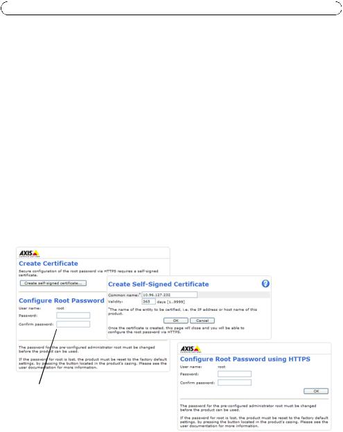
To gain access to the product, the password for the default administrator user root must be set. This is done in the ‘Configure Root Password’ dialog, which is displayed when the network camera is accessed for the first time.
To prevent network eavesdropping when setting the root password, this can be done via an encrypted HTTPS connection, which requires an HTTPS certificate.
Note: HTTPS (Hypertext Transfer Protocol over SSL) is a protocol used to encrypt the traffic between web browsers and servers. The HTTPS certificate controls the encrypted exchange of information.
To set the password via a standard HTTP connection, enter it directly in the first dialog shown below.
To set the password via an encrypted HTTPS connection, follow these steps:
1.Click the Create self-signed certificate button.
2.Provide the requested information and click OK. The certificate is created and the password can now be set securely. All traffic to and from the network camera is encrypted from this point on.
3.Enter a password and then re-enter it to confirm the spelling. Click OK. The password has now been configured.
To create an HTTPS connection, start by clicking this button.
To configure the password directly via an unencrypted connection, enter the password here.
4.To log in, enter the user name “root” in the dialog as requested. Note: The default administrator user name root cannot be deleted.
AXIS P13-E Network Camera Series Installation Guide |
Page 17 |
5.Enter the password as set above, and click OK.
Note: If the password is lost, the camera must be reset to the factory default settings. See page 27.
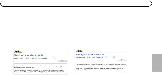
6.AXIS P1346-E/AXIS P1347-E: The capture mode must be set the first time AXIS P1346-E/AXIS P1347-E is accessed. Select the desired capture mode from the drop-down list and click OK.
AXIS P1346-E |
AXIS P1347-E |
ENGLISH
Note: The capture mode can be changed later from the product’s web pages, but this will reset most other settings. For more information, see the online help or User’s Manual.

Page 18 |
AXIS P13-E Network Camera Series Installation Guide |
Access the video stream
The Live View page of the network camera is displayed, with links to the Setup tools, which allow you to customize the camera.
If required, click Yes to install AMC (AXIS Media Control), which allows viewing of the video stream in Internet Explorer. You will need administrator rights on the computer to do this.
If required, click the link to install missing decoders.
Note: To install AMC in Windows Vista and Windows 7, you must run Internet Explorer as administrator. Right-click the Internet Explorer icon and select Run as administrator.
Setup – Provides all the tools for configuring the camera to requirements.
Help – Displays online help on all aspects of using the camera.
AXIS P13-E Network Camera Series Installation Guide |
Page 19 |
 Adjust zoom and focus
To adjust the zoom and focus follow these instructions:
1.Open the product’s home page and go to Setup > Basic Setup > Focus.
2.On the Basic tab, click Open iris. If the button is inactive, the iris is already open.
3.If focus has been set before, click Reset to reset the back focus.
4.Loosen the zoom and focus pullers on the lens by turning them anti-clockwise. Move the pullers to set zoom and focus and check the quality of the image in the image window.
Note:
If the camera is mounted so that one cannot look at the image and move the pullers at the same time, use the Focus Assistant instead. See page 20.
5.Retighten the zoom and focus pullers.
6.On the Focus page, click Fine-tune focus automatically and wait until the automatic finetuning is completed.
7.Click Enable iris. If the button is inactive, the iris has already been enabled.
8.If needed, make further adjustments on the Advanced tab. See the online help or User’s Manual for more information.
Notes:
•Set focus as precisely as possible with the focus puller or Focus Assistant before starting the automatic fine-tuning. Using the focus puller normally gives the best result.
•The iris should always be opened to its maximum while focusing, which gives the smallest depth of field and thus the best conditions for correct focusing.
Focus puller
Control button
Zoom puller
Status LED
ENGLISH
Example image: AXIS P1343-E

Page 20 |
AXIS P13-E Network Camera Series Installation Guide |
Focus Assistant
To focus using the Focus Assistant, follow the instructions in steps 1 - 3 on page 19 before you start with the steps below.
1.Mount or place the camera so that it cannot be moved.
2.Loosen the zoom puller by turning it anti-clockwise. Move the puller to set the zoom level. Retighten the zoom puller.
3.Set the camera to its extreme distant-focus position by loosening the focus puller and turning the lens fully clockwise.
4.Press and quickly release the Control button. When the Status LED flashes green, the Focus Assistant is enabled.
If the Status LED flashes either red or amber before you are able to adjust the lens, skip to step 7 to exit the Focus Assistant and repeat steps 3 - 7. See the notes below.
5.Gently turn the lens anti-clockwise until it stops.
6.Finally, turn the lens slowly clockwise until the status indicator flashes green or amber (not red).
7.To exit the Focus Assistant, press the Control button again.
Note: The Focus Assistant is switched off automatically after 15 minutes.
8.Retighten the focus puller.
9.Open the Live View page in the web browser and check the quality of the image.
10.Continue with steps 6 - 8 on page 19.
Notes:
•The view in front of the camera should not be changed during focus adjustment (steps 5 and 6). If the camera is moved, or if a finger or other object is placed in front of the lens, steps 3 - 7 will have to be repeated.
•If movements in front of the camera cannot be avoided, the Focus Assistant should not be used.
•If the Control button is not released within two seconds, AXIS Dynamic DNS Service is enabled instead of the Focus Assistant.
•If the camera is mounted so that the Control button cannot be accessed, you can still use the Focus Assistant. Follow the instructions above but mount the camera after step 4 (pressing the Control button) instead and skip step 7.
AXIS P13-E Network Camera Series Installation Guide |
Page 21 |
Other methods of setting the IP address
The table below shows the other methods available for setting or discovering the IP address. All methods are enabled by default, and all can be disabled.
|
Use in operating |
Notes |
|
|
|
system |
|
|
|
|
|
|
|
|
UPnP™ |
Windows |
When enabled on your computer, the camera is automatically |
|
|
|
|
detected and added to My Network Places/Network. |
|
|
|
|
|
|
|
Bonjour |
MAC OSX |
Applicable to browsers with support for Bonjour. Navigate to the |
|
ENGLISH |
|
(10.4 or later) |
Bonjour bookmark in your browser (e.g. Safari) and click on the |
|
|
|
|
|
||
|
|
link to access the camera’s web pages. |
|
|
|
|
|
|
|
AXIS Dynamic DNS |
All |
A free service from Axis that allows you to quickly and simply |
|
|
Service |
|
install your camera. Requires an Internet connection with no |
|
|
|
|
HTTP proxy. See www.axiscam.net for more information. |
|
|
|
|
|
|
|
ARP/Ping |
All |
See below. The command must be issued within 2 minutes of |
|
|
|
|
connecting power to the camera. |
|
|
DHCP Server |
All |
To view the admin pages for the network DHCP server, see the |
|
|
|
|
server’s own documentation. |
|
|
|
|
|
|
|
AXIS Video Hosting System (AVHS)
The camera can also be connected to an AVHS service for hosted video. If you have subscribed to an AVHS service, follow the instructions in the Service Provider’s Installation Guide. For more information and help to find a local AVHS Service Provider, go to www.axis.com/hosting
A Camera owner authentication key is supplied with this product. The key is associated with the camera’s unique serial number (S/N) as shown on the top of the label.
Note:
Save the key for future reference.

Page 22 |
AXIS P13-E Network Camera Series Installation Guide |
Set the IP address with ARP/Ping
1.Acquire a free static IP address on the same network segment your computer is connected to.
2.Locate the serial number (S/N) on the product label on the camera.
3.Open a command prompt on your computer and enter the following commands:
Windows syntax: |
Windows |
example: |
|
|
|
arp -s <IP Address> <Serial Number> |
arp -s 192.168.0.125 00-40-8c-18-10-00 |
|
ping -l 408 -t <IP Address> |
ping -l |
408 -t 192.168.0.125 |
UNIX/Linux/Mac syntax: |
UNIX/Linux/Mac example: |
|
|
|
|
arp -s <IP Address> <Serial Number> temp |
arp -s 192.168.0.125 00:40:8c:18:10:00 temp |
|
ping -s 408 <IP Address> |
ping -s |
408 192.168.0.125 |
4.Check that the network cable is connected to the camera and then start/restart the camera, by disconnecting and reconnecting power.
5.Close the command prompt when you see ‘Reply from 192.168.0.125:...’ or similar.
6.In your browser, type in http://<IP address> in the Location/Address field and press Enter on your keyboard.
Notes:
•To open a command prompt in Windows: from the Start menu, select Run... and type cmd. Click OK.
•To use the ARP command in Windows Vista, right-click the command prompt icon and select
Run as administrator.
•To use the ARP command on a Mac OS X, use the Terminal utility in Application > Utilities.
Unit connectors
Network connector - RJ-45 Ethernet connector. Supports Power over Ethernet. Using shielded cables is recommended.
Power connector - 2-pin connector block used for power input (not used). |
|
|
|
Audio in - 3.5 mm input for a mono microphone, or a line-in mono signal (left |
|
|
|
channel is used from a stereo signal). |
|
|
|
Audio out - Audio output (line level) that can be connected to a public address (PA) |
1 |
2 |
|
system or an active speaker with a built-in amplifier. A pair of headphones can also |
|||
|
|
be attached. A stereo connector must be used for the audio out.
AXIS P13-E Network Camera Series Installation Guide |
Page 23 |
SDHC memory card slot - A standard or high capacity SD memory card can be used for local recording with removable storage.
SD memory card slot
To insert an SD card, lift the SD card cover on the rear of the network camera, and carefully insert the SD card into its slot.
To remove an SD card lift the cover and gently push the card in and release it. The SD card will back out of the slot where it can then be removed.
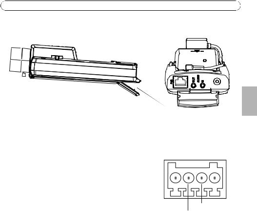
I/O terminal connector - Used in applications for e.g. motion detection, event triggering, time lapse recording and alarm notifications. In addition to an auxiliary power and a GND pin, it provides the interface to:
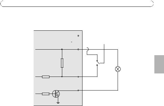
•1 digital output – For connecting external devices such as relays and LEDs. Connected devices can be activated by the VAPIX® Application Programming Interface (API), by the output buttons on the Live View page or by an Event Type. The output will show as active (shown under Events > Port Status) if the alarm device is activated.
Pin 4 |
|
|
Pin 2 |
|
|||
|
|
Pin 3 |
Pin 1 |
•1 digital input – An alarm input for connecting devices that can toggle between an open and closed circuit, for example: PIRs, door/window contacts, glass break detectors, etc. When a signal is received the state changes and the input becomes active (shown under
Events > Port Status).
ENGLISH

Page 24 |
AXIS P13-E Network Camera Series Installation Guide |
Note:
The I/O connector on the network camera is connected to the housing electronics at delivery and will trigger an input port event to indicate a fan or heater error when activated. Please refer to the User’s Manual, available on the CD provided with this product, or from www.axis.com, for information on how to set up an event.
Function |
Pin |
Notes |
Specifications |
|
|
|
|
GND |
1 |
Ground |
|
|
|
|
|
3.3 V DC |
2 |
Can be used to power auxiliary equipment. |
Max load = 50 mA |
Power |
|
Note: This pin can only be used as power out. |
|
|
|
|
|
Digital |
3 |
Connect to GND to activate, or leave floating |
Min. input = -40 V DC |
Input |
|
(unconnected) to deactivate. |
Max. input= +40 V DC |
|
|
Note: Connected to housing electronics at delivery. |
|
|
|
|
|
Digital |
4 |
Uses an open-drain NFET transistor with the source |
Max. load =100 mA |
Output |
|
connected to GND. If used with an external relay, a |
Max. voltage = + 40 V DC |
|
|
diode must be connected in parallel with the load, |
|
|
|
for protection against voltage transients. |
|
|
|
|
|
AXIS P13-E Network Camera Series Installation Guide |
Page 25 |
Connection diagram
The following connection diagram gives an example of how to connect an auxiliary device to the network camera.
|
|
1 |
|
|
|
|
|||
|
|
|
|
|
|
|
|
|
E.g. push button |
|
|
|
|
|
|
|
|
|
|
3.3V |
|
|
|
|
|
|
|
||
|
|
|
|
|
|
|
|
||
max. 50mA |
2 |
|
|
|
|
||||
|
|
||||||||
ENGLISH
|
3 |
D |
4 |
|
|
G |
|
S |
|
LED indicators
LED |
Color |
Indication |
|
|
|
Network |
Green |
Steady for connection to a 100 Mbit/s network. Flashes for network activity. |
|
|
|
|
Amber |
Steady for connection to 10 Mbit/s network. Flashes for network activity. |
|
|
|
|
Unlit |
No network connection. |
|
|
|
Status |
Green |
Steady green for normal operation. |
|
|
Note: The Status LED can be configured to be unlit during normal operation, or to |
|
|
flash only when the camera is accessed. To configure, go to Setup > System |
|
|
Options > LED settings. See the online help files for more information. |
|
|
|
|
Amber |
Steady during startup, during reset to factory default or when restoring settings. |
|
|
|
|
Red |
Slow flash for failed upgrade. |
|
|
|
Power |
Green |
Normal operation. |
|
|
|
|
Amber |
Flashes green/amber during firmware upgrade. |
|
|
|

Page 26 |
AXIS P13-E Network Camera Series Installation Guide |
Status LED when using the Focus Assistant
LED |
Color |
Indication |
|
|
|
|
Green |
Step 4: Focus Assistant is enabled |
|
|
Step 6: The lens is optimally adjusted |
|
|
|
|
Amber |
Step 4: The camera has been moved, or an object has been inserted in front of |
|
|
the lens. Exit and restart the Focus Assistant. |
|
|
Step 6: The lens is less optimally adjusted |
|
|
|
|
Red |
Step 4: The camera has been moved, or an object has been inserted in front of |
|
|
the lens. Exit and restart the Focus Assistant. |
|
|
Step 6: The lens is poorly adjusted |
|
|
|
Status LED on housing electronics (fan/heater)
LED |
Color |
Indication |
|
|
|
Power |
Green |
OK |
|
|
|
|
Flashing |
Single flash: Heater error |
|
green |
Double flash: Fan error |
|
|
Triple flash: General error |
|
|
Note: Alarm events will be triggered through the camera’s input port. See the |
|
|
User’s Manual, available on the CD provided with this product, or from |
|
|
www.axis.com Contact your Axis reseller for information about spare parts and |
|
|
troubleshooting. |
|
|
|

AXIS P13-E Network Camera Series Installation Guide |
Page 27 |
Resetting to the Factory Default settings
This will reset all parameters, including the IP address and focus position, to the Factory Default settings:
1. |
Disconnect power from the camera. |
|
|
2. |
Press and hold the control button and reconnect power. |
|
|
3. |
Keep the control button pressed until the status indicator displays amber (this may take up to |
|
|
|
15 seconds). |
|
|
4. |
Release the control button. When the status indicator displays green (which can take up to 1 |
|
|
ENGLISH |
|||
|
minute) the process is complete and the network camera has been reset. |
||
|
|
||
5. |
Re-assign the IP address, using one of the methods described in this document. |
|
|
6. |
Refocus the camera, using one of the methods described in this document. |
|
It is also possible to reset parameters to the original factory default settings via the web interface. For more information, please see the online help or the User’s Manual.
Accessing the camera from the Internet
Once installed, your network camera is accessible on your local network (LAN). To access the camera from the Internet, network routers must be configured to allow incoming traffic, which is usually done on a specific port
•HTTP port (default port 80) for viewing and configuration
•RTSP port (default port 554) for viewing H.264 video streams
Please refer to the documentation for your router for further instructions. For more information on this and other topics, visit the Axis Support Web at www.axis.com/techsup
Further information
The User’s Manual is available from the Axis Web site at www.axis.com or from the AXIS Network Video Product CD supplied with this product.
Tip!
Visit www.axis.com/techsup to check if there is updated firmware available for your network camera. To see the currently installed firmware version, see Setup > About.

Page 28 |
AXIS P13-E Network Camera Series Installation Guide |

Mesures de sécurité
Lisez attentivement le présent Guide d'installation avant d'installer le produit Axis. Conservez le Guide d'installation pour une utilisation ultérieure.
|
|
|
|
|
• Conservez le produit Axis dans un environnement sec et aéré. |
|
|||
• Évitez d'exposer le produit Axis aux vibrations, aux chocs ou à une forte pression. |
|
|||
|
N'installez pas le produit sur un support instable, ou des surfaces ou des murs instables ou |
|
||
|
vibrants, car cela pourrait l'endommager. |
|
||
• N'utilisez que les outils applicables pour installer le produit Axis ; une force excessive |
|
|||
|
pourrait endommager le produit. |
|
||
• Pour le nettoyage, n’utilisez ni produits chimiques, ni substances caustiques ou aérosols. |
|
|||
|
Utilisez un chiffon humide pour le nettoyage. |
|
||
• N’utilisez que des accessoires conformes aux caractéristiques techniques du produit. Ceux- |
|
|||
AISÇFRAN |
||||
|
ci peuvent être fournis par Axis ou par un fournisseur tiers. |
|||
|
|
|||
• Utilisez uniquement des pièces de rechange fournies ou recommandées par Axis. |
|
|||
• Ne tentez pas de réparer le produit vous-même, contactez Axis ou votre revendeur Axis |
|
|||
|
pour toute réparation. |
|
||
|
|
|||
|
|
|
||
• Ce produit Axis doit être utilisé conformément aux lois et réglementations locales en |
|
|||
|
vigueur. |
|
||
Transport
•Pour transporter le produit Axis et éviter de l'endommager, utilisez l'emballage d'origine ou un emballage équivalent.

Remplacement des piles
Ce produit Axis nécessite une pile au lithium CR2032 de 3,0 V pour l'alimentation de son horloge en temps réel interne. Dans des conditions normales d'utilisation, cette pile est censée durer au moins 5 ans. Si la pile est faible, le fonctionnement de l'horloge en temps réel peut être affecté et entraîner sa réinitialisation à chaque mise sous tension. Un message enregistré apparaît lorsque la pile doit être remplacée. Ne remplacez la pile qu'en cas de nécessité !
Si la pile doit être remplacée, veuillez contacter www.axis.com/techsup pour obtenir de l’aide.
•Jetez les piles usagées conformément aux consignes du fabricant.
•Le remplacement incorrect de la pile peut entraîner un risque d'explosion.
•Remplacez la pile par une pile identique ou équivalente uniquement, en respectant les recommandations du fabricant.
Loading...