


 Loading...
INSTALLATION GUIDE
AXIS P12 Network Camera Series
AXIS P1204 Network Camera
AXIS P1214 Network Camera
AXIS P1214-E Network Camera
AXIS P1224-E Network Camera
ESPAÑOL ITALIANO DEUTSCH AISÇFRAN ENGLISH
About this Document
This document includes instructions for installing AXIS P12 Network Camera series on your network. Previous experience of networking will be beneficial when installing the product.
Legal Considerations
Video and audio surveillance can be prohibited by laws that vary from country to country. Check the laws in your local region before using this product for surveillance purposes. This product includes one (1) H.264 decoder license. To purchase further licenses, contact your reseller.
Trademark Acknowledgments
Apple, Boa, Bonjour, Ethernet, Internet Explorer, Linux, Microsoft, Mozilla, Real, SMPTE, QuickTime, UNIX, Windows, Windows Vista and WWW are registered trademarks of the respective holders. Java and all Java-based trademarks and logos are trademarks or registered trademarks of Oracle and/or its affiliates. UPnPTM is a certification mark of the UPnPTM Implementers Corporation.
Electromagnetic Compatibility (EMC)
This equipment has been designed and tested to fulfill applicable standards for:
•Radio frequency emission when installed according to the instructions and used in its intended environment.
•Immunity to electrical and electromagnetic phenomena when installed according to the instructions and used in its intended environment.
USA - This equipment has been tested using a shielded network cable (STP) and found to comply with the limits for a Class B digital device, pursuant to part 15 of the FCC Rules. These limits are designed to provide reasonable protection against harmful interference in a residential installation. This equipment generates, uses and can radiate radio frequency energy and, if not installed and used in accordance with the instructions, may cause harmful interference to radio communications. However, there is no guarantee that interference will not occur in a particular installation. If this equipment does cause harmful interference to radio or television reception, which can be determined by turning the equipment off and on, the user is encouraged to try to correct the interference by one or more of the following measures:
•Reorient or relocate the receiving antenna.
•Increase the separation between the equipment and receiver.
•Connect the equipment into an outlet on a circuit different from that to which the receiver is connected.
•Consult the dealer or an experienced radio/TV technician for help.
Canada - This Class B digital apparatus complies with Canadian ICES-003.
Europe - This digital equipment fulfills the requirements for RF emission according to the Class B limit of EN 55022.
This product fulfills the requirements for immunity according to EN 61000-6-1 residential, commercial and light-industrial environments.
This product fulfills the requirements for immunity according to EN 55024 residential and commercial environments.
Australia - This digital equipment fulfills the requirements for RF emission according to the Class B limit of AS/NZS CISPR 22.
Japan - B
Korea - |
|
% |
|
|
|
|
|
|
|
|
|
|
|
|
|
|
|
|
|
|
Safety
This product complies with IEC/EN/UL 60950-1, Safety of Information Technology Equipment. The power supply used with this product shall fulfill the requirements for Safety Extra Low Voltage (SELV) and Limited Power Source (LPS) according to IEC/EN/UL 60950-1.
AXIS P1214-E/AXIS P1224-E Sensor Unit: This product complies with IEC/EN/UL 60950-1 and IEC/EN/UL 60950-22, Safety of Information Technology Equipment.
Equipment Modifications
This equipment must be installed and used in strict accordance with the instructions given in the user documentation. This equipment contains no user-serviceable components. Unauthorized equipment changes or modifications will invalidate all applicable regulatory certifications and approvals.
Liability
Every care has been taken in the preparation of this document. Please inform your local Axis office of any inaccuracies or omissions. Axis Communications AB cannot be held responsible for any technical or typographical errors and reserves the right to make changes to the product and documentation without prior notice. Axis Communications AB makes no warranty of any kind with regard to the material contained within this document, including, but not limited to, the implied warranties of merchantability and fitness for a particular purpose. Axis Communications AB shall not be liable nor responsible for incidental or consequential damages in connection with the furnishing, performance or use of this material. This product is only to be used for its intended purpose.
RoHS
This product complies with both the European RoHS directive, 2002/95/EC, and the Chinese RoHS regulations, ACPEIP.
WEEE Directive
The European Union has enacted a Directive 2002/96/EC on Waste Electrical and Electronic Equipment (WEEE Directive). This directive is applicable in the European Union member states. The WEEE marking on this product (see right) or its
documentation indicates that the product must not be disposed of together with household waste. To prevent possible harm to human health and/or the environment, the product must be disposed of in an approved and environmentally safe recycling process. For further information on how to dispose of this product correctly, contact the product supplier, or the local authority responsible for waste disposal in your area.
Business users should contact the product supplier for information on how to dispose of this product correctly. This product should not be mixed with other commercial waste.
Support
Should you require any technical assistance, please contact your Axis reseller. If your questions cannot be answered immediately, your reseller will forward your queries through the appropriate channels to ensure a rapid response. If you are connected to the Internet, you can:
•download user documentation and firmware updates
•find answers to resolved problems in the FAQ database. Search by product, category, or phrases
•report problems to Axis support by logging in to your private support area

Safeguards
Please read through this Installation Guide carefully before installing the Axis product. Keep the Installation Guide for further reference.
|
|
|
|
• Store the Axis product in a dry and ventilated environment. |
|
||
• Avoid exposing the Axis product to vibration, shocks or heavy pressure. Do not install the |
|
||
|
product on unstable brackets, unstable or vibrating surfaces or walls, since this could cause |
|
|
|
damage to the product. |
|
|
• Only use applicable tools when installing the Axis product; excessive force could cause |
ENGLISH |
||
|
damage to the product. |
||
|
|
||
• Do not use chemicals, caustic agents, or aerosol cleaners. Use a damp cloth for cleaning. |
|
||
• Use only accessories that comply with technical specification of the product. These can be |
|
||
|
|||
|
provided by Axis or a third party. |
|
|
• Use only spare parts provided by or recommended by Axis. |
|
||
• Do not attempt to repair the product by yourself, contact Axis or your Axis reseller for ser- |
|
||
|
vice matters. |
|
|
|
|
||
|
|
|
|
• This Axis product shall be used in compliance with local laws and regulations. |
|
||
Transportation
•When transporting the Axis product, use the original packaging or equivalent to prevent damage to the product.

Battery Replacement
This Axis product uses a 3.0 V BR2032 or CR2032 lithium battery as the power supply for its internal real-time clock (RTC). Under normal conditions this battery will last for a minimum of 5 years. Low battery power affects the operation of the RTC, causing it to reset at every power-up. A log message will appear when the battery needs replacing. The battery should not be replaced unless required!
If the battery does need replacing, please contact www.axis.com/techsup for assistance.
•Dispose of used batteries according to the manufacturer's instructions.
•Risk of explosion if battery is incorrectly replaced.
•Replace only with the same or equivalent battery, as recommended by the manufacturer.

AXIS P12 Series Installation Guide |
Page 5 |
AXIS P12 Network Camera Series
Installation Guide
This Installation Guide provides instructions for installing AXIS P12 Network Camera on your network. For all other aspects of using the product, please see the User Manual, available at www.axis.com
Installation Steps
1.Check the package contents against the list below.
2.Hardware overview. See page 6.
3.Install the hardware. See page 12
4.Access the Axis Product. See page 20.
 Package Contents
Item |
Models/variants/notes |
|
|
Network camera |
Main unit |
|
Sensor unit AXIS P1204/AXIS P1214/AXIS P1214-E/AXIS P1224-E/ |
|
|
Connectors |
2-pin power terminal block |
|
4 pin I/O connector terminal block |
|
|
Mounting Accessories |
All variants: Mounting rail |
|
AXIS P1204: Straight mounting bracket, angled mounting bracket, cover |
|
AXIS P1214/AXIS P1224-E: Mounting bracket |
|
AXIS P1214-E: Mounting bracket, outdoor housing |
|
|
CD |
Installation and Management Software CD, including installation tools and |
|
other software |
|
|
Printed materials |
AXIS P12 Series Installation Guide (this document) |
|
Axis Warranty Document |
|
AVHS Authentication key |
|
|
ENGLISH

Page 6 |
AXIS P12 Series Installation Guide |
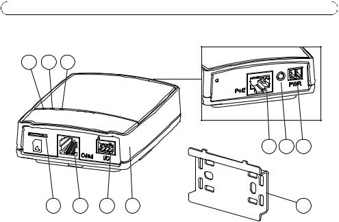
 Hardware Overview
1 2 3
8 9 10
4 |
5 |
6 |
7 |
11 |
1 |
Power indicator LED |
7 |
Main unit |
2 |
Status indicator LED |
8 |
Network connector see page 9 |
3 |
Network indicator LED |
9 |
Control button |
4 |
MicroSD card slot |
10 |
Power connector see page 9 |
5 |
Camera connector, see page 9 |
11 |
Mounting rail |
6I/O terminal connector see page 9
AXIS P12 Series Installation Guide |
Page 7 |
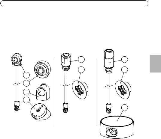
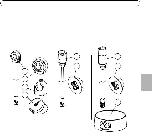
AXIS P1204 sensor |
AXIS P1214 sensor |
AXIS P1214-E sensor |
unit and included |
unit and included |
unit and included |
accessories |
accessories |
accessories |
16 |
17 |
12 |
13 |
14 |
15 |
18 |
ENGLISH |
|
17 |
||
|
19 |
12 |
AXIS P1204 sensor unit |
16 |
AXIS P1214 sensor unit |
13 |
Cover |
17 |
Mounting bracket |
14 |
Straight mounting bracket |
18 |
AXIS P1214-E sensor unit |
15 |
Angled mounting bracket |
19 |
Outdoor housing |
Page 8 |
AXIS P12 Series Installation Guide |
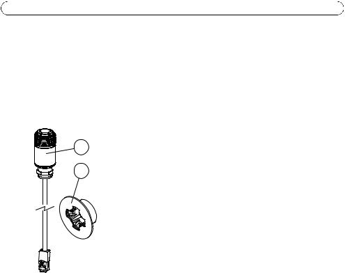
AXIS P1224-E sensor unit and included accessories
20
17 |
17 Mounting bracket
20 AXIS P1224-E sensor unit
AXIS P12 Series Installation Guide |
Page 9 |
Connectors
Network - RJ45 Ethernet connector. Supports PoE (Power over Ethernet, class 2).
Due to local regulations or the environmental and electrical conditions in which the product is to be used, a shielded network cable (STP) may be appropriate or required. Any network cables that are routed outdoors or in demanding electrical environments shall be shielded (STP) and intended for their specific use. Make sure the network switch is properly grounded. See
Electromagnetic Compatibility (EMC) for regulatory requirements.
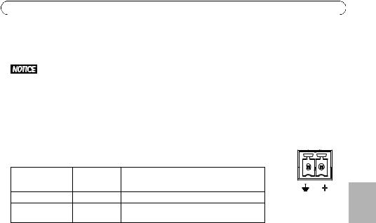
Power connector - 2-pin terminal block for power input.
|
|
|
|
|
|
|
|
|
|
|
|
|
|
|
|
|
|
|
|
Function |
|
Pin number |
Description |
|
|
|
|
|
|
|
|
|
|
|
|
|
|
|
|
|
|
|
|
|
|
|
|
|
|
|
|
|
|
|
|
|
|
|
|
|
|
|
|
|
|
|
|
|
|
|
|
|
|
|
|
|
|
|
|
|
|
|
|
|
|
|
|
|
|
|
|
|
|
|
|
|
|
|
|
GND |
|
1 |
Ground |
|
|
|
|
|
|
|
|
|
|
|
|
|
|
|
|
|
|
|
|
|
|
|
|
|
|
|
|
|
|
|
|
|
|||
|
|
|
|
|
|
|
|
|
|
|
1 |
|
2 |
|
|||||
DC Power |
|
2 |
Power input 8-28 V DC |
|
|
|
|
|
|
|
|||||||||
|
|
|
max 4.7 W |
|
|
|
|
|
|
|
|
|
|
|
|
|
|
|
|
|
|
|
|
|
|
|
|
|
|
|
|
|
|
|
|
|
|
|
|
Camera connector - RJ12 connector. |
|
|
|
|
|
|
|
|
|
|
|
|
|
|
|||||
I/O terminal connector - Use in applications for e.g. motion detection, |
|
|
|
|
|
|
|
|
|
|
|
|
|
|
|
||||
|
|
|
|
|
|
|
|
|
|
|
|
|
|
|
|||||
event triggering, time lapse recording and alarm notifications. In addition |
|
|
|
|
|
|
|
|
|
|
|
|
|
|
|
||||
to an auxiliary power and a GND pin, the I/O terminal connector provides |
|
|
|
|
|
|
|
|
|
|
|
|
|
|
|
||||
|
1 |
2 |
|
3 |
|
4 |
|
|
|
||||||||||
the interface to: |
|
|
|
|
|
|
|
|
|
||||||||||
|
|
|
|
|
|
|
|
|
|
|
|
|
|
|
|
|
|
||
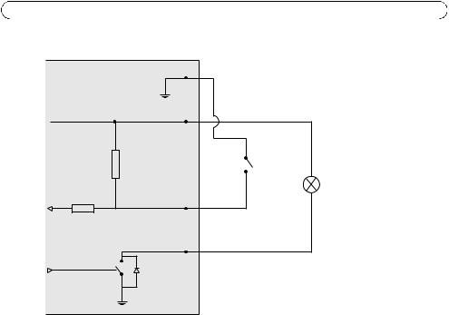
•Digital output — For connecting external devices such as relays and LEDs. Connected devices can be activated by the VAPIX® Application Programming Interface, output buttons on the Live View page or by an Action Rule. The output will show as active (shown under
System Options > Port & Devices > Port Status) if the alarm device is activated.
•Digital input — An alarm input for connecting devices that can toggle between an open and closed circuit, for example: PIRs, door/window contacts, glass break detectors, etc. When a signal is received the state changes and the input becomes active (shown under System Options > Port & Devices > Port Status).
Function |
Pin number |
Notes |
Specifications |
|
|
|
|
GND |
1 |
Ground |
|
|
|
|
|
3.3 V DC |
2 |
Can be used to power auxiliary equipment. |
Max load = 50 mA |
Power |
|
Note: This pin can only be used as power out. |
|
|
|
|
|
Input |
3 |
Digital input - Connect to GND to activate, or |
0 to +40 V DC |
|
|
leave floating (or unconnected) to deactivate. |
|
|
|
|
|
Output |
4 |
Digital output - Internal connection to |
Max load = 100 mA |
|
|
ground when activated, floating |
Max voltage = +40 V DC |
|
|
(unconnected) when deactivated. If used |
|
|
|
with an external relay, a diode must be |
|
|
|
connected in parallel with the load, for |
|
|
|
protection against voltage transients. |
|
|
|
|
|
ENGLISH
Page 10 |
AXIS P12 Series Installation Guide |
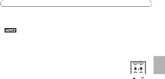
Connection diagram
|
1 |
3.3 V max 50 mA |
2 |
|
3 |
|
4 |
SD card slot - A standard or high-capacity microSD card (not included) can be used for local recording with removable storage.
Note: Before removal, the SD card should be unmounted to prevent corruption of recordings. To unmount the SD card, go to Setup > System Options > Storage > SD Card and click Unmount.
AXIS P12 Series Installation Guide Page 11
Camera LED Indicators
LED |
Color |
Indication |
|
|
|
|
|
|
|
Network |
Green |
Steady for connection to a 100 MBit/s network. Flashes for network activity. |
|
|
|
|
|
|
|
|
Amber |
Steady for connection to a 10 MBit/s network. Flashes for network activity. |
|
|
|
|
|
|
|
|
Unlit |
No network connection. |
|
|
|
|
|
|
|
Status |
Green |
Steady green for normal operation. |
|
|
|
|
|
|
|
|
Amber |
Steady during startup and when restoring settings. |
|
|
|
|
|
|
|
|
Red |
Slow flash for failed upgrade. |
|
ENGLISH |
|
|
|
|
|
|
Unlit |
No connection between sensor unit and main unit. |
|
|
|
|
|
||
|
|
|
|
|
Power |
Green |
Normal operation. |
|
|
|
|
|
|
|
|
Amber |
Flashes green/amber during firmware upgrade. |
|
|
|
|
|
|
|
Note: The Status and Network LEDs can be configured to be unlit during normal operation. To configure, go to Setup > System Options > Ports & Devices > LED. See the online help for more information.
Page 12 |
AXIS P12 Series Installation Guide |
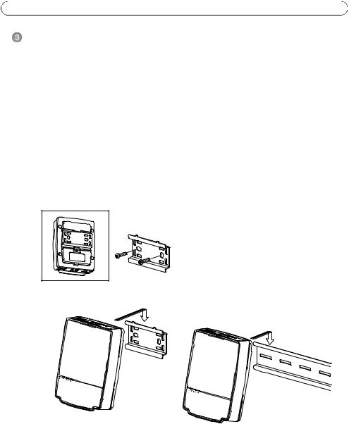
Install the hardware
!IMPORTANT! - The casing of the main unit is not approved for outdoor use - the product may only be installed in indoor environments.
Make a note of the serial number (S/N) located on the product label. This number may be required during installation.
The main unit for the AXIS P1204/P1214/P1214-E/P1224-E can be mounted on a DIN rail or using the supplied mounting rail.
1.If using the mounting rail, fasten it with screws to the wall or ceiling, using screws and plugs appropriate for the wall/ceiling material. Note the direction of the two tabs on the rail, the tabs align with the upper side of the main unit.
2.Attach the upper end of the main unit to the DIN rail or the mounting rail and snap the lower end into place.
3.Proceed with the instructions for the appropriate camera model below.
AXIS P12 Series Installation Guide |
Page 13 |
AXIS P1204 Sensor Unit
!IMPORTANT! - The casing of the AXIS P1204 sensor unit is not approved for outdoor use - the product may only be installed in indoor environments.
The AXIS P1204 can be mounted in three different ways:
•flat on any surface
•angled on any surface, using the angled fastening bracket
•covertly behind a thin material, for example a metal sheet in a doorpost or an ATM machine.
Flat Surface Installation
1.Fasten the camera to the wall or ceiling, using screws and plugs appropriate for the wall/ceiling material.
2.Snap on the cover.
3.Proceed to Connect the cables, on page 19.
ENGLISH
Page 14 |
AXIS P12 Series Installation Guide |
Angled Surface Installation
1.Fasten the angled mounting bracket to the wall or ceiling, using screws and plugs appropriate for the wall/ceiling material. Ensure that the bracket is pointing towards the area to be monitored.
2.Assemble the plate with the screw and align it so the arrows are vertical or horizontal.
3.Fasten the camera to the plate with the two screws.
4.Snap on the cover.
5.Proceed to Connect the cables, on page 19.
AXIS P12 Series Installation Guide |
Page 15 |
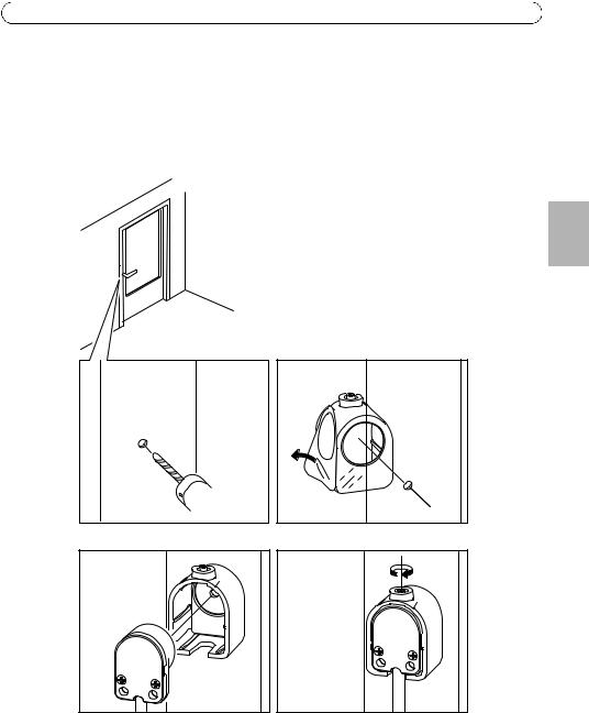
Covert Installation
1.Drill a hole with 3mm diameter in the wall or ceiling. If the material is thicker than 1mm it may be necessary to expand the hole with a countersink cutter.
2.Pull off the protection on the adhesive and attach the straight mounting bracket to the wall.
3.Insert the camera into the bracket, and fasten with the stop screw. Ensure that the cone of the camera is flush with the wall.
4.Proceed to Connect the cables, on page 19.
ENGLISH

Page 16 |
AXIS P12 Series Installation Guide |
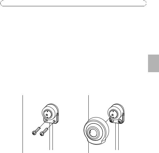
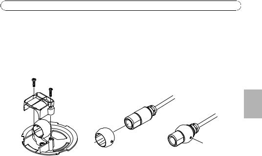
AXIS P1214/AXIS P1224-E Sensor Unit
!IMPORTANT! - The casing of the AXIS P1214 sensor unit is not approved for outdoor use - the product may only be installed in indoor environments.
The AXIS P1214/AXIS P1224-E can be mounted behind any wall, with just a small opening for the lens, or with the whole lens assembly protruding through the wall.
1.Drill a hole with 20mm diameter in the wall, either completely through the material, or use a countersink cutter to have a smaller opening.
2.Pull off the protection on the adhesive and attach the mounting bracket to the wall. Optionally secure the bracket with two screws through the holes.
3.Insert the camera and tighten the lock ring as shown in the image below. Position the camera so that the flat surface on the thread is vertical or horizontal.
4.Proceed to Connect the cables, on page 19.
 Lock ring
AXIS P12 Series Installation Guide |
Page 17 |
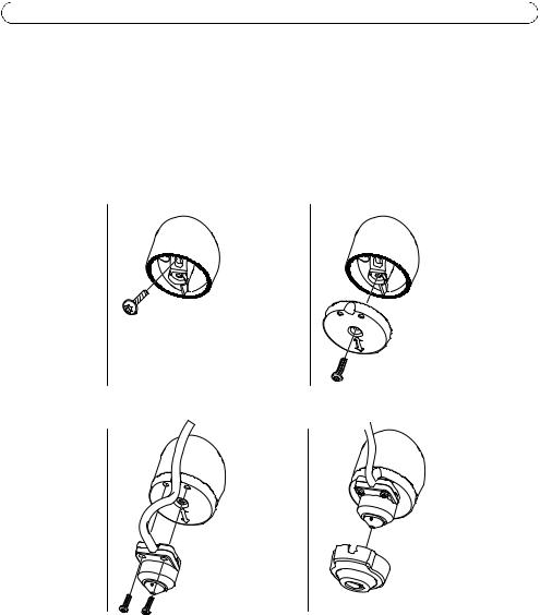
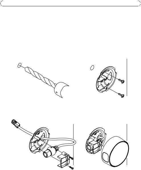
AXIS P1214-E Sensor Unit
The AXIS P1214-E can be mounted like the AXIS P1214/AXIS P1224-E, see instructions above.
The AXIS P1214-E can also be mounted in the supplied outdoor housing. The cables can be routed through the wall directly into the housing, or through one of the punch-outs in the cover.
1.Remove the two screws and the bracket.
2.Insert the camera into the ball joint and fasten with the stop screw.
ENGLISH
Page 18 |
AXIS P12 Series Installation Guide |
3.Drill a hole through the wall or remove one of the punch-outs in the cover.
4.Fasten the plate to the wall using screws and plugs appropriate for the wall material. Ensure that the camera bracket is pointing towards the area to be monitored. If routing the cable through the wall, align the cut-out in the plate with the hole in the wall.
5.Place the ball in the socket and fasten the bracket with the screws. Aim the camera away from the wall before tightening the screws. Position the camera so that the flat surface on the thread is vertical or horizontal.
6.Route the cable through the wall, or through the punch-out in the cover.
7.Attach the cover.
8.Proceed to Connect the cables, on page 19.

AXIS P12 Series Installation Guide Page 19
Connect the cables
1. |
Optionally connect external input/output devices, e.g. alarm devices. See page 9 for information |
|
|
on the terminal connector pins. |
|
2. |
Connect the main unit to the network using a shielded network cable. |
|
3. |
Connect the sensor unit to the main unit. If required, the cable can be shortened. See the User |
|
|
Manual for further information. |
|
4. |
Connect power, using one of the methods listed below: |
|
|
• PoE (Power over Ethernet, Class 2). If available, this is automatically detected when the |
|
|
network cable is connected. |
|
|
ENGLISH |
|
|
• Connect power via the terminal connector. See page 9 for information on the terminal con- |
|
|
|
|
|
nector pins. |
|
5. |
Check that the indicator LEDs indicate the correct conditions. See the table on page 11 for |
|
|
further details. Note that some LEDs can be disabled and may be unlit. |
|
Page 20 |
AXIS P12 Series Installation Guide |
 Access the Axis Product
Use the software provided on the Installation and Management Software CD to assign an IP address, set the password and access the video stream.
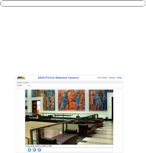
The Live View Page
The product’s Live View page appears in your browser. Click Setup to open the product’s Setup pages, which allow you to customize the Axis product.
Setup - Provides all the tools for |
Help - Displays online help |
|||
configuring the product to require- |
on all aspects of using the |
|||
ments. |
camera. |
|||
|
|
|
|
|
|
|
|
|
|
|
|
|
|
|
AXIS P12 Series Installation Guide |
Page 21 |
Resetting to the Factory Default Settings
If the Axis product needs to be reset to factory default, follow these steps:
1.Disconnect power.
2.Press and hold the Control button and reconnect power.
3.Keep the Control button pressed for about 15 seconds until the Status indicator flashes amber.
4.Release the Control button. The process is complete after about 1 minute (when the Status indicator turns green). The product has been reset to the factory default settings.
Further Information
The User Manual is available from the Axis Web site at www.axis.com
Tip!
Visit www.axis.com/techsup to check if there is updated firmware available for your network camera. To see the currently installed firmware version, see Setup > About.
Learn more!
Visit Axis learning center www.axis.com/academy for useful trainings, webinars, tutorials and guides.
Warranty
For information about Axis’ product warranty and thereto related information, see www.axis.com/warranty
ENGLISH

Mesures de sécurité
Lisez attentivement le présent Guide d'installation avant d'installer le produit Axis. Conservez le Guide d'installation pour une utilisation ultérieure.
|
|
|
|
|
• Conservez le produit Axis dans un environnement sec et aéré. |
|
|||
• Évitez d'exposer le produit Axis aux vibrations, aux chocs ou à une forte pression. |
|
|||
|
N'installez pas le produit sur un support instable, ou des surfaces ou des murs instables ou |
|
||
|
vibrants, car cela pourrait l'endommager. |
|
||
• N'utilisez que les outils applicables pour installer le produit Axis ; une force excessive |
|
|||
|
pourrait endommager le produit. |
|
||
• Pour le nettoyage, n’utilisez ni produits chimiques, ni substances caustiques ou aérosols. |
|
|||
|
Utilisez un chiffon humide pour le nettoyage. |
|
||
• N’utilisez que des accessoires conformes aux caractéristiques techniques du produit. Ceux- |
|
|||
AISÇFRAN |
||||
|
ci peuvent être fournis par Axis ou par un fournisseur tiers. |
|||
|
|
|||
• Utilisez uniquement des pièces de rechange fournies ou recommandées par Axis. |
|
|||
• Ne tentez pas de réparer le produit vous-même, contactez Axis ou votre revendeur Axis |
|
|||
|
pour toute réparation. |
|
||
|
|
|||
|
|
|
||
• Ce produit Axis doit être utilisé conformément aux lois et réglementations locales en |
|
|||
|
vigueur. |
|
||
Transport
•Pour transporter le produit Axis et éviter de l'endommager, utilisez l'emballage d'origine ou un emballage équivalent.

Remplacement des piles
Ce produit Axis nécessite une pile au lithium CR2032 ou BR2032 de 3,0 V pour l'alimentation de son horloge en temps réel interne. Dans des conditions normales d'utilisation, cette pile est censée durer au moins 5 ans. Si la pile est faible, le fonctionnement de l'horloge en temps réel peut être affecté et entraîner sa réinitialisation à chaque mise sous tension. Un message enregistré apparaît lorsque la pile doit être remplacée. Ne remplacez la pile qu'en cas de nécessité !
Si la pile doit être remplacée, veuillez contacter www.axis.com/techsup pour obtenir de l’aide.
•Jetez les piles usagées conformément aux consignes du fabricant.
•Le remplacement incorrect de la pile peut entraîner un risque d'explosion.
•Remplacez la pile par une pile identique ou équivalente uniquement, en respectant les recommandations du fabricant.

Séríe AXIS P12 Guide d’installation |
Page 25 |
Série de caméras réseau AXIS P12 Guide d’installation
Ce guide d'installation vous explique comment installer une Caméra réseau AXIS P12 sur votre réseau. Pour tous les autres aspects liés à l'utilisation de ce produit, veuillez consulter le Manuel de l'utilisateur, disponible sur www.axis.com.
Procédure d’installation
1.Vérifiez que l’emballage contient bien tous les éléments répertoriés dans la liste ci-dessous.
2.Aperçu du matériel. Reportez-vous à la page 24.
3.Installation du matériel. Reportez-vous à la page 33.
4.Accès au produit Axis. Reportez-vous à la page 41.
 Contenu du module
Élément |
Modèles/variantes/remarques |
|
|
Caméra réseau |
Unité principale |
|
Unité optique AXIS P1204/AXIS P1214/AXIS P1214-E/AXIS P1224-E |
|
|
Connecteurs |
Bloc de connexion à 2 broches pour l'alimentation en entrée. |
|
Bloc de connexion à 4 broches pour E/S |
|
|
Accessoires de montage |
Toutes les variantes : Rail de fixation |
|
AXIS P1204 : Support de fixation droit, support de fixation oblique, couvercle |
|
AXIS P1214/AXIS P1224-E: Support de fixation |
|
AXIS P1214-E: Support de fixation, boîtier externe |
|
|
CD |
Le CD d'installation et de gestion du logiciel, y compris les outils d'installation |
|
et au autre logiciel |
|
|
Documentation imprimée |
Guide d'installation de la série AXIS P12 (le présent document) |
|
Document de garantie d’Axis |
|
Clé d’authentification AVHS |
|
|
AISÇFRAN
Page 26 |
Séríe AXIS P12 Guide d'installation |
 Vue d’ensemble du matériel
1 2 3
8 9 10
4 |
5 |
6 |
7 |
11 |
1 |
Voyant DEL d’alimentation |
7 |
Unité principale |
2 |
Voyant DEL d’état |
8 |
Connecteur réseau, voir page 29 |
3 |
Voyant DEL réseau |
9 |
Bouton de commande |
4 |
Emplacement carte SD (carte |
10 |
Connecteur d'alimentation, voir |
|
microSD) |
|
page 29 |
5 |
Connecteur caméra, voir |
11 |
Rail de fixation |
|
page 29 |
|
|
6Connecteur pour terminaux E/S, voir page 26
Séríe AXIS P12 Guide d’installation |
Page 27 |
Unité optique |
Unité optique |
Unité optique |
AXIS P1204 et |
AXIS P1214 et |
AXIS P1214-E et |
accessoires inclus |
accessoires inclus |
accessoires inclus |
16 |
17 |
12 |
13 |
14 |
15 |
18 |
17 |
AISÇFRAN
19 |
12 |
Unité optique AXIS P1204 |
16 |
Unité optique AXIS P1214 |
13 |
Cache de protection |
17 |
Support de fixation |
14 |
Support de fixation droit |
18 |
Unité optique AXIS P1214-E |
15 |
Support de fixation oblique |
19 |
Boîtier externe |

Page 28 |
Séríe AXIS P12 Guide d'installation |
Unité optique AXIS P1224-E et accessoires inclus
20
17 |
17 Support de fixation
20 Unité optique AXIS P1224-E
Séríe AXIS P12 Guide d’installation |
Page 29 |
Connecteurs
Réseau - Connecteur Ethernet RJ45. Prend en charge PoE (alimentation par Ethernet, classe 2).
Conformément à la règlementation locale et étant donné les conditions électriques et environnementales dans lesquelles le produit doit être utilisé, un câble réseau blindé (STP) peut convenir, voire être obligatoire. Les câbles réseau acheminés vers l'extérieur ou dans des environnements électriques exigeants doivent être blindés (STP) et destinés à leur usage spécifique. Assurez-vous que le commutateur réseau est correctement mis à la terre. Voir Electromagnetic Compatibility (EMC) pour les exigences liées à la règlementation.
Connecteur d’alimentation - Bloc terminal à 2 broches pour l'entrée de courant.
Fonction |
Numéro de |
Description |
|
|
|
broche |
|
|
|
GND (Terre) |
1 |
Mise à la terre |
1 |
2 |
Alimentation CC |
2 |
Entrée de courant 8-28 V CC |
|
|
|
|
max. 4,7 W |
|
|
Connecteur de la caméra - Connecteur RJ12.
AISÇFRAN
Page 30 |
Séríe AXIS P12 Guide d'installation |
Connecteur pour terminaux d’E/S - À utiliser dans les applications pour, |
|
|
|
|
|
par exemple, la détection de mouvement, le déclenchement d'évènement, |
|
|
|
|
|
l'enregistrement image par image et les notifications d'alarmes. Outre une |
1 |
2 |
3 |
4 |
|
alimentation auxiliaire et une broche GND, le connecteur pour terminaux |
|||||
|
|
|
|
E/S fournit une interface de :
•Sortie numérique : permet de connecter des dispositifs externes, comme des relais ou des DEL. Les dispositifs connectés peuvent être activés par l'Interface de Programmation de l'Application VAPIX®, les boutons de sortie sur la page Vidéo en direct ou par une Règle d'action. La sortie est considérée comme étant active (dans System Options > Port & Devices >Port Status (Options Systèmes > Ports et périphériques > État du port)) si le dispositif d'alarme est activé.
•Entrée numérique : entrée d'alarme utilisée pour connecter des dispositifs pouvant passer d'un circuit ouvert à un circuit fermé, par exemple : détecteurs infrarouge passifs, contacts de porte/fenêtre, détecteurs de bris de verre, etc. Lorsqu'un signal est reçu, l'état change et l'entrée devient active (sous System Options > Port & Devices > Port Status (Options Systèmes>Ports et périphériques-État du port)).
Fonction |
Numéro de |
Remarques |
Caractéristiques |
|
broche |
|
techniques |
|
|
|
|
GND (Terre) |
1 |
Mise à la terre |
|
|
|
|
|
Alimentation |
2 |
Peut servir à alimenter le matériel auxiliaire. |
Charge maximale = |
3,3V CC |
|
Remarque : Cette broche ne peut être utilisée |
50 mA |
|
|
que comme sortie d’alimentation. |
|
|
|
|
|
Entrée |
3 |
Entrée numérique : connectez-la à la terre |
de 0 à +40 V CC |
|
|
pour l’activer ou laissez-la flotter (ou |
|
|
|
déconnectée) pour la désactiver. |
|
|
|
|
|
Sortie |
4 |
Sortie numérique : connexion interne à la |
Charge max. = 100 |
|
|
terre lorsqu’activée, flottante (déconnectée) |
mA |
|
|
lorsque désactivée. En cas d'utilisation avec |
Tension maximale = |
|
|
un relais externe, une diode doit être |
+40 V CC |
|
|
connectée en parallèle avec la charge en |
|
|
|
guise de protection contre les tensions |
|
|
|
transitoires. |
|
|
|
|
|
Loading...