


 Loading...
Avaya A6000, AP41, AP60, AP61, AP65 User Manual
...Configuration Guide
VIEW Certified
Aruba Mobility Controller
Configuration and Deployment Guide
SpectraLink’s Voice Interoperability for Enterprise Wireless (VIEW) Certification Program is designed to ensure interoperability and high performance between wireless IP telephones and WLAN infrastructure products. The products noted below have been thoroughly tested in SpectraLink’s lab and have passed VIEW Certification. This document details how to configure the Aruba mobility controller for use with wireless IP telephones.
Certified Product Summary
Manufacturer: |
Aruba Networks: www.arubanetworks.com |
|
|||
|
|
|
|
|
|
Approved products: |
Wireless Controllers |
|
Access Points |
|
|
|
|
|
|
|
|
|
A200 |
|
AP41 |
|
|
|
A800 |
|
AP60 |
|
|
|
A2400 |
|
AP61 |
|
|
|
A6000 † |
|
AP65 |
|
|
|
|
|
AP70 † |
|
|
|
|
|
|
|
|
RF technology: |
802.11b/g/a |
|
|
|
|
|
|
|
|
|
|
Radio: |
2.4 GHz (802.11 b/g), 5 GHz (802.11a) |
|
|
||
|
|
|
|
|
|
Security : |
WPA2-PSK |
|
|
|
|
|
|
|
|
|
|
AP firmware version tested: |
2.5.4.X |
|
|
|
|
|
|
|
|
|
|
Handset models |
3616/3620/3626 |
|
|
3641/3645 |
|
|
|
|
|
|
|
Radio mode |
802.11b |
802.11b |
802.11g |
802.11a |
|
|
|
|
|
|
|
Maximum telephone calls per AP: |
12 |
|
|
12* |
|
|
|
|
|
|
|
Network topology: |
Switched Ethernet (recommended) |
|
|
||
|
|
|
|
|
|
† Denotes products directly used in Certification Testing
*Maximum calls tested during VIEW Certification and the recommended setting in the AVPP. The certified product may actually support a higher number of calls for 802.11a and 802.11g radio modes.
Service Information
If you encounter difficulties or have questions regarding the configuration process, please contact Aruba Networks technical support at 1-800-943-4526, visit www.arubanetworks.com/support or e-mail support@arubanetworks.com.
© Copyright 2007 Avaya, Inc. All rights reserved |
|
21-601645, Issue 1, May 2007 |
Page 1 |
Aruba Mobility Controller |
Configuration Guide |
|
VIEW Certified |
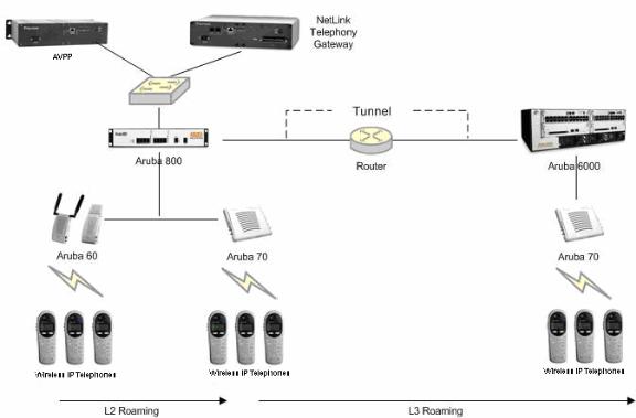
Network Topology
The following topology was tested during VIEW Certification testing.
Deployment Description
It is required that voice users be placed on a separate VLAN (e.g., VLAN 10) and data users on a separate VLAN (e.g., VLAN 25). The voice and data VLANs reside on the Aruba mobility controller and not on the access points (APs). The user traffic is tunneled back to the Aruba controller for processing. The edge network thus does not have to be modified to accommodate the WiFi clients and the VoWiFi network. Map each VLAN to a unique subnet. The mobility controller (switch) IP address needs to be set via the loopback interface setting. The Controller’s loopback address must be a routable address so that the APs can reach this address.
Interface setting
Identify the mobility controller port that serves as the uplink port for the data VLAN. The port used in this example is Fast Ethernet 1/0 and is a trunk port with both the voice and data VLAN.
Default route
The L3 switch connected to the Aruba controller serves as the default gateway for all the WiFi clients. Configure the default route to the next-hop gateway connected to the mobility controller.
Physical interface
All interfaces that connect to the core networks, routers, servers and gateways need to be set as trusted ports.
Page 2
Aruba Mobility Controller |
Configuration Guide |
|
VIEW Certified |
Connecting the APs
The APs need an IP address for communication with the mobility controller. The APs can connect to the controller over a L2 or L3 network. Ensure that DHCP is enabled on the subnets the APs are connected to and can ping the Aruba mobility controller’s “switch IP address” from their current subnet.
Known Limitations
No limitations were discovered during VIEW Certification testing.
VIEW Certification testing verifies that the wireless telephone and the AP interoperate at the packet level; therefore, no add-on vendor features were tested in the scope of VIEW.
Connecting to the Mobility Controller
Command, comment, and screen text key
In the sections below you will find commands, comments, prompts, system responses, or other screen-displayed information involved in the configuration process. This key explains the text styles and symbols used to denote them.
Text Style |
Denotes: |
|
|
xxxxxxxx |
Typed command |
|
|
<xxxxxxxx> |
Encryption key, domain name or other information |
|
specific to your system that needs to be entered |
|
|
(xxxxxxxx) |
Comment about a command or set of commands |
|
|
xxxxxxxx |
Prompt, system response or other displayed information |
|
|
Via console
1.Using a standard RS-232 cable, connect the mobility controller to the serial port of a terminal or PC.
2.Run a terminal emulation program (such as HyperTerminal) or use a VT-100 terminal with the following configuration:
Bits per second: |
9600 |
|
|
Data bits: |
8 |
|
|
Parity: |
None |
|
|
Stop bits: |
1 |
|
|
Flow control: |
None |
|
|
3.Press Enter to display the Aruba mobility controller login screen.
4.Enter the default login: admin and the default password: admin. These are case sensitive.
5.Enter enable and the default password: admin to get into the command mode.
Page 3

Aruba Mobility Controller |
Configuration Guide |
|
VIEW Certified |
Via the CLI
By default, only SSH (Secure SHell) access to the switch (mobility controller) is permitted.
1.From a management system that has network connectivity to the switch, connect to the switch using SSH:
ssh admin@<switch IP address>
2.Enter the admin password at the password prompt.
3.Type enable at the > prompt to enter the enable mode.
4.Type the enable password when prompted for a password.
Via the Web interface
Once the connectivity to the switch is verified, open a Web browser and enter the switch’s IP address in the navigator bar.
The switch can be accessed using http, http://<switch IP Address> or https, https://<switch IP Address>:4343.
The user is prompted with the username and password configured (in the example above, the username/password configured is admin/admin). On successful login the following
Network Summary screen is displayed:
Page 4
Aruba Mobility Controller |
Configuration Guide |
|
VIEW Certified |
Initial Setup
Before starting, please ensure that the Policy Enforcement Firewall module license is enabled on the Aruba mobility controller. Please contact Aruba Networks for licenses and installation information.
On power-up, the user is presented with the startup wizard:
Enter System name [Aruba800]: Aruba
Enter VLAN 1 interface IP address [172.16.0.254]: Enter VLAN 1 interface subnet mask [255.255.255.0]: Enter IP Default gateway [none]:
Enter Switch Role, (master|local) [master]: master
Enter Country code (ISO-3166), <ctrl-I> for supported list: US You have chosen Country code US for United States (yes|no)?: yes Enter Password for admin login (up to 32 chars): admin
Re-type Password for admin login: admin
Enter Password for enable mode (up to 15 chars): enable Re-type Password for enable mode: enable
Do you wish to shutdown all the ports (yes|no)? [no]: no
Current choices are:
System name: Aruba
VLAN 1 interface IP address: 172.16.0.254
VLAN 1 interface subnet mask: 255.255.255.0
IP Default gateway: none
Switch Role: master
Country code: US
Ports shutdown: no
If you accept the changes the switch will restart!
Type <ctrl-P> to go back and change answer for any question. Do you wish to accept the changes (yes|no)yes
. . . . .
<<<<< |
Welcome to Aruba Wireless Networks - Aruba 800 >>>>> |
. . . . |
|
(Aruba) |
|
User: |
|
Page 5
Aruba Mobility Controller |
Configuration Guide |
|
VIEW Certified |
Assigning an IP to the Mobility Controller
1.Connect to the switch via the CLI.
2.Login with the configured username and password, admin /admin in this example.
3.Type enable at the > prompt.
4.Type the enable password, enable in this example.
5.Type configure terminal at the # prompt.
6.Create the vlan for the voice (vlan 25) using the vlan command:
(Aruba) (config) #vlan 25
7.Create the vlan interface.
(Aruba) (config) #interface vlan 25
8.Assign the IP address to the interface.
(Aruba) (config-subif)#ip address 10.168.10.2 255.255.255.0
9.Create the loopback interface and assign an IP address to the loopback. For more information about the loopback interface refer to the user guide.
(Aruba) (config) #interface loopback (Aruba) (config-loop)#ip address 10.168.10.1
Switch IP Address is Modified. Switch should be rebooted now (Aruba) (config-loop)#!
(Aruba) (config) #ip default-gateway 10.168.10.10
10.Assign a physical interface to the vlan. In this example, the interface connecting to the network is a trunk interface. Configure the mode on the interface to a trunk mode.
(Aruba) (config) #interface fastethernet 1/0 (Aruba) (config-if)#trusted
(Aruba) (config-if)#no shutdown
(Aruba) (config-if)#switchport mode trunk
(Aruba) (config-if)#switchport trunk allowed vlan add 10,25 (Aruba) (config-if)#!
(Aruba) (config)#
11.Ping the default gateway from the switch’s console.
12.Ping the switch’s IP address from the management station.
Connecting APs
Provisioning APs
The APs need to be provisioned. The Aruba APs can be provisioned manually or be configured for automatic provisioning. For manual provisioning, use the Web-based AP provisioning Web page. Refer to the AP Provisioning User Guide for instructions on provisioning the AP.
The APs can communicate with the controller over a L2 or L3 network. The only requirement is that each AP be assigned an IP address and default gateway using DHCP.
Page 6
Loading...