


VME 9512 TS
52

D |
Wir gratulieren Ihnen! Durch Ihre kluge Wahl sind Sie Besitzer eines AUDIOVOX Mobile Video-Produktes geworden. |
|
AUDIOVOX Mobile Video-Produkte erfreuen sich aufgrund der hohen Qualität eines ausgezeichneten Rufes weltweit. Dieser hohe Qualitätsstandard ermöglicht es für AUDIOVOX Mobile Video-Produkte 2 Jahre Garantie zu gewähren.
Die Produkte werden während des gesamten Fertigungsvorganges laufend kontrolliert und geprüft. Im Servicefall beachten Sie bitte folgendes:
1.Die Garantiezeit beginnt mit dem Kauf des Produktes und gilt nur für den Erstbesitzer.
2.Während der Garantiezeit beseitigen wir etwaige Mängel, die nachweislich auf Materialoder Fabrikationsfehler beruhen, nach unserer Wahl durch Austausch oder Nachbesserung der defekten Teile. Weitergehende Ansprüche, insbesondere auf Minderung, Wandlung, Schadenersatz oder Folgeschäden sind ausgeschlossen. Die Garantiezeit wird von einer Garantieleistung durch uns nicht berührt.
3.Am Produkt dürfen keine unsachgemäßen Eingriffe vorgenommen worden sein.
4.Bei Inanspruchnahme der Garantie wenden Sie sich bitte zunächst an Ihren Fachhändler. Sollte es sich als notwendig erweisen, das Produkt an uns einzuschicken, so sorgen Sie bitte dafür, dass • das Produkt in einwandfreier Originalverpackung verschickt wird, • die Kontrollkarte ausgefüllt dem Produkt beiliegt, • die Kaufquittung beigefügt ist.
5.Von der Garantie ausgenommen sind: • Leuchtmittel • Verschleißteile •Transportschäden, sichtbar oder unsichtbar (Reklamationen für solche Schäden müssen umgehend bei der Transportfirma, Bahn oder Post eingereicht werden.) • Kratzer in Metallteilen, Frontabdeckungen u.s.w. (Diese Defekte müssen innerhalb von 5 Tagen nach Kauf direkt bei Ihrem Händler reklamiert werden.) • Fehler, die durch fehlerhafte Aufstellung, falschen Anschluss, unsachgemäße Bedienung (siehe Bedienungsanleitung), Beanspruchung oder äußere gewaltsame Einwirkung entstanden sind. • Unsachgemäß reparierte oder geänderte Geräte, die von anderer Seite als von uns geöffnet wurden. • Folgeschäden an fremden Geräten • Kostenerstattung bei Schadensbehebung durch Dritte ohne unser vorheriges Einverständnis.
GB |
Congratulations! You have made a wise selection in becoming the owner of a AUDIOVOX Mobile Video equipment. Due |
|
to high quality AUDIOVOX products have earned an excellent reputation through the western world. And this high quality standard enables us to grant a 2-years warranty for AUDIOVOX Mobile Video products.
The equipments are checked and tested continously during the entire production process. In case you have problems with your AUDIOVOX Mobile Video equipment, kindly observe the following:
1.The guarantee period commences with the purchase of the component and is applicable only to the original owner.
2.During the guarantee period we will rectify any defects due to faulty material or workmanship by replacing or repairing the defective part at our discretion. Further claims, and in particular those for price reduction, cancellation of sale, compensation for damages or subsequential damages, are excluded. The guarantee period is not altered by the fact that we have carried out guarantee work.
3.Unauthorized tampering with the equipment will invalidate this guarantee.
4.Consult your authorized dealer first, if guarantee service is needed. Should it prove necessary to return the component to the factory, please insure that • the component is packed in original factory packing in good condition • the quality control card has been filled out and enclosed with the component, • your enclose your receipt as proof of purchase.
5.Excluded from the guarantee are: • Illuminates • Wear parts • Shipping damages, either readily apparent or concealed (claims for such damages must be lodged immediately with forwarding agent, the railway express office or post office). • Scratches in cases, metal components, front panels, etc. (You must notify your dealer directly of such defects within three days of purchase.)
• Defects caused by incorrect installation or connection, by operation errors (see operating instructions), by overloading or by external force. • Equipments which have been repaired incorrectly or modified or where the case has been opened by persons other than us. • Consoquential damages to other equipments. • Reimbursement of cools, without our prior consent, when repairing damages by third parties.
F |
Toutes nos félicitations! |
|
Vouz avez bien choisi et êtes le propriétaire heureux d’un produit AUDIOVOX. Les produits AUDIOVOX ont une excellente réputation pour leur bonne qualité. Pour cette raison, nous accordons 2 ans de garantie sur les produits AUDIOVOX.
Les appareils sont soumis pendant toutes les opérations de fabrications à des contrôles et vérifications constants. Si, pourtant, vous rencontrez des difficulés avec votre appareil AUDIOVOX veuillez tenir compte de ce qui suit:
1.La garantie débute avec l’achat de l’appareil et est valable uniquement pour le premier propriétaire.
2.Pendant la période de garantie nous réparons les dommages provenant des défauts de matériel ou de fabrication et nous procédons, à notre guise, à l’échange ou à la réparation des pièces défectueuses.
3.Aucune réparation impropre ne doit avoir été effectuée à l’appareil.
4.Lors d’une demande de garantie, veuillez vous adresser en premier lieu à votre distributeur. Si ce dernier décide que l’appareil doit nous être retourné, veuillez tenir compte que: • l’appareil soit expédié dans son ermballage d’origine, • la carte de contrôle dûment remplie soit jointe, • le bon d’achat soit joint.
5.Ne sont pas compris dans la garantie: • Matériel d’eclairage • Pièces d’usure • Avaries de transport, visibles ou non (de telles réclamations doivent être faites immédiatement auprès du transporteur, du chermin de fer ou de la poste). • Des rayures sur le boîtier, pièces métalliques, couvercles etc. (ces dommages doivent être signalés directement à votre distributeur dans les trois jours suivant l’achat). • Dommages résultant d’un raccordement incorrect, maniement incorrect (voir instructions de service), surcharge ou application de force extérieure. • Appareils réparés non conformément ou modifiés et qui ont été ouverts par une personne autre que nous. • Dommages ultérieurs à d’autres appareils. • Remboursement des frais à des tiers ayant effectué les réparations sans notre accord préalable.

GARANTIEKARTE
WARRANTY CARD
Typ/Type
Serien-Nr./Serial-No.
Name und Anschrift des Händlers/Stempel
Name and address of the dealer/stamp
Käufer/Customer
Name/Name
Straße/Street
PLZ, Ort/City
Land/Country
Kaufdatum/buying date
Nur gültig in Verbindung mit Ihrer Kaufquittung!
No warranty without receipt!

Audiovox Audio Produkte GmbH
Lise-Meitner-Str. 9 • D-50259 Pulheim • Germany Tel. ++49 (0) 2234 807-0 • Fax++49 (0) 2234 807-399 www.audiovox-germany.de

Thank you for choosing a Audiovox product. We hope you will find the instructions in this owner’s manual clear and easy to follow. If you take a few minutes to look through it, you’ll learn how to use all the features of your new Audiovox VME 9512 TS Mobile Multimedia Receiver for maximum enjoyment.
Preparation |
|
54 |
Optional Equipment |
|
55 |
Warning |
|
56 |
Wiring Diagram |
|
57 |
Media Link |
|
58 |
Installation |
|
59 |
Anti-Theft Feature |
|
61 |
Controls and Indicators |
|
62 |
Remote Control |
|
64 |
Using the TFT Monitor |
|
67 |
Operating Instructions |
|
69 |
Multi-ZONE Operation |
|
71 |
Setup Menu |
|
72 |
Tuner Operation |
|
77 |
DVB-T Operation |
|
80 |
DVD/VCD Video Operation |
|
81 |
DVD/CD Audio Operation |
|
85 |
MP3/WMA/iPod Operation |
|
87 |
Bluetooth Operation |
|
94 |
Troubleshooting |
|
98 |
Care and Maintenance |
100 |
|
|
|
|
Specifications |
101 |
|
|
|
|
Subject to technical changes
53

PREPARATION
Congratulations on your purchase of the Audiovox VME 9512 TS
Mobile Multimedia Receiver.
It’s a good idea to read all of the instructions before beginning the installation. We recommend having your Audiovox VME 9512 TS installed by a reputable installation shop.
Features
DVD
•Aspect Ratio - Cinema, Normal and OFF (Standby)
•Fast Forward, Fast Reverse - 2X, 4X and 8X
•Slow Forward, Slow Reverse - 2X, 4X and 8X
•Play, Pause, Stop, Next Chapter and Previous Chapter
•ESP - 2MB Buffer
CD / MP3 / WMA
•ID3 Tag Compatible
•Directory Search (MP3 / WMA Only)
•Direct Track Access via Remote control
•Burn Up To 1500 MP3 and WMA Files onto a DVD+R /RW
•Audible Forward / Reverse Track Search
•Random, Repeat and Intro
•Play, Pause, Stop, Next Track and Previous Track
•ESP - 2MB Buffer
AM-FM-RDS
•USA/Europe/Latin America/Asia Frequency Spacing
•30 Station Presets (18 FM, 12 AM)
•Auto Stereo/Mono
•Local/Distance
•Auto Store/Preview Scan
•RDS (Radio Data System)
DVB-T Ready (optional DVB-T 999 connectable) User friendly OSD Menu with Full Function
• Very easy broadcast search
iPod
•jLinkDirect - High Speed Direct Connect Interface to Access iPod Playlists, Artists, Albums, Songs, **Photos and **Video (** Requires Photo or Video iPod)
•Power Management Charges iPod while Connected
•Requires jLinkCable iPod Interface Cable (sold seperately)
MediaLink4
• Under Dash Interface Allows Portable Media Devices to be Connected
• MediaLink4 Includes the Following connectivity:
• USB - Supports Hard Drives and Flash Memory Drives (up to 500 mA)
• LinkDirect 8-pin DIN for iPod
• 3.5mm Audio Only Input
• CA Audio / Video Input
Chassis |
|
|
• 1.0 DIN (Import/ISO-DIN Mountable) |
changes |
|
• 7" TFT Active Matrix LCD with Anti-Glare Coating |
||
• Motorized/Swivel Flip-Out/Flip-Up LCD Screen |
technicaltoSubject |
|
• Screen Tilt/Angle Adjustment |
||
|
||
• Heat Management System - Forced-Air Cooling to Keep the Chip Sets Operating at Nominal Temperatures |
|
54

General
•Bluetooth - Bluetooth hands-free profile for safety / convenience and A2DP profile for streaming music from a PDA / PMP and Mobilphone
•Navigation Ready (Nav101and NAV1352 TS)
•38-Key Infrared Remote Control with 5-way Joystick
•One Composite Video Outputs for Additional Screens
•Compatible with LCM 972 TS Rear Seat Monitor with Touch Screen Interface
•One Audio / Video Auxiliary Input
•200-Ohm Preamp Line Output - All Audio Channels
•4VRMS Line Output - All Channels
•Rotary Encoder Audio Control
•Seven-Band EQ with Eight Preset EQ Curves
•Spectrum Analyzer
•Front, Rear, Center and Subwoofer Line Output
•Subwoofer Crossover and Phase Control
•Dolby Digital / Pro-Logic ll
•Programmable Volume Control
•Rear Camera Input (Normal and Mirror Image View)
•Auto TFT Dimmer
•5-Way Joystick
Optional Equipment
• NAV101 / NAV 1352 TS
The VME 9512 TS is "navigation ready." Before accessing any navigation features, you must purchase and install the NAV module. All installation and operating instructions will be included with the NAV navigation module. Once the NAV is connected and operating properly, the NAV source mode will become active. While the NAV is not installed, the NAV option appears gray, indicating the function is not available.
• Rear Camera
The VME 9512 TS is "camera ready." Before accessing any camera features, you must purchase and install a rear video camera. Once the rear camera is connected and operating properly, the CAMERA source mode will become active. While the camera is not installed, the CAMERA option appears gray, indicating the function is not available.
• DVB-T
See “DVB-T Opertation” on page 29.
• iPod
See “MP3/WMA Operation” on page 36.
• Bluetooth Phone
See “Bluetooth Operation” on page 43.
Tools and Supplies
You will need these tools and supplies to install your VME 9512 TS:
•Torx type, flat-head and Philips screwdrivers
•Wire cutters and strippers
•Tools to remove existing radio (screwdriver, socket wrench set or other tools)
•Electrical tape
•Crimping tool
•Volt meter/test light
•Crimp connections
•18 gauge wire for power connections
•16 – 18 gauge speaker wire
Disconnecting the Battery
To prevent a short circuit, be sure to turn off the ignition and remove the negative (-) battery cable prior to installation.
Subject to technical changes
55

NOTE:
If the VME 9512 TS is to be installed in a car equipped with an on-board drive or navigation computer, do not disconnect the battery cable. If the cable is disconnected, the computer memory may be lost. Under these conditions, use extra caution during installation to avoid causing a short circuit.
WARNING! Only connect the unit to a12-volt power supply with proper grounding.
WARNING! Never install this unit where operation and viewing could interfere with safe driving conditions.
WARNING! To reduce the risk of a traffic accident (except when using for rear view video camera) never use the video display function while driving the vehicle. This is a violation of federal law.
WARNING! Never disassemble or adjust the unit.
WARNING! To prevent injury from shock or fire, never expose this unit to moisture or water.
WARNING! Never use irregular discs.
WARNING! To prevent damage to the mechanism inside this unit, avoid impact to the TFT monitor.
WARNING! Using an improper fuse may cause damage to the unit and result in a fire.
WARNING! The monitor employs an automatic motorized mechanism. To prevent damage to the core mechanism, please do not push, pull or swivel the monitor manually, other than in the manner explained in “Monitor Left/Right Angle Adjustment” on page 16.
Subject to technical changes
56
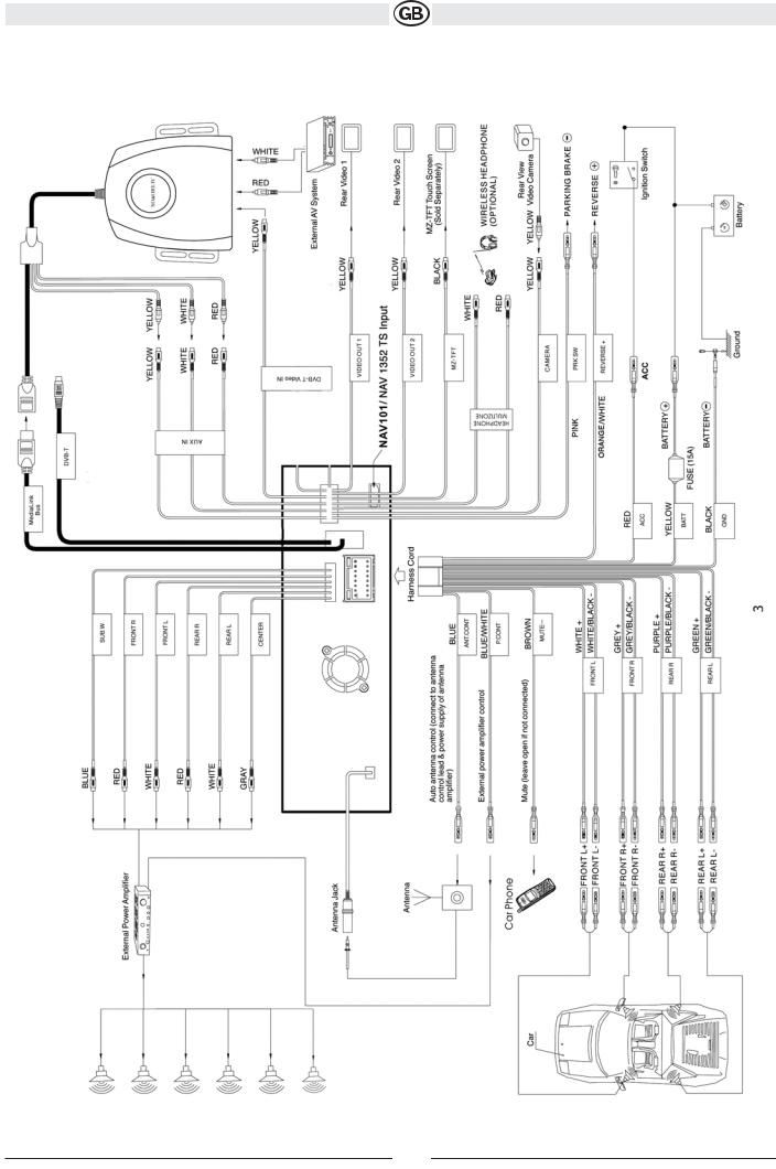
Wiring Diagram
Subject to technical changes
57
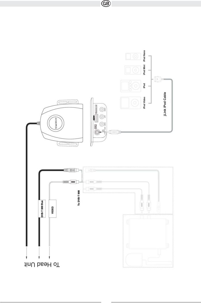
Medialink
Subject to technical changes
58
INSTALLATION
Pre-installation
1. Press the metal levers on both sides to remove the halfsleeve from the radio.
2. Install the half-sleeve.
a.Install adapter if necessary (optional).
b.Install half-sleeve into adapter or dashboard (use only the supplied screws). Do not force the sleeve into the opening or cause it to bend or bow.
c.Locate the series of bend-tabs along the top,
bottom and sides of the mounting sleeve. With the sleeve fully inserted into the dashboard opening, bend as many of the tabs outward as necessary so that the sleeve is firmly secured to the dashboard.
d. Install support strap to make the unit more stable.
CAUTION! Be careful not to damage the car wiring.
3. Place the radio in front of the dashboard opening so the wiring can be brought through the mounting sleeve.
Wiring
Complete wiring as illustrated in the wiring diagram on page 6. Once the wiring is complete, reconnect the battery negative terminal. If there is no ACC available, connect the ACC lead to the power supply with a switch.
NOTE:
When replacing a fuse, be sure to use correct type and amperage to avoid damaging the radio. The VME 9512 TS uses one 15 amp mini-ATM fuse, located in the black filter box in-line with the main wire harness.
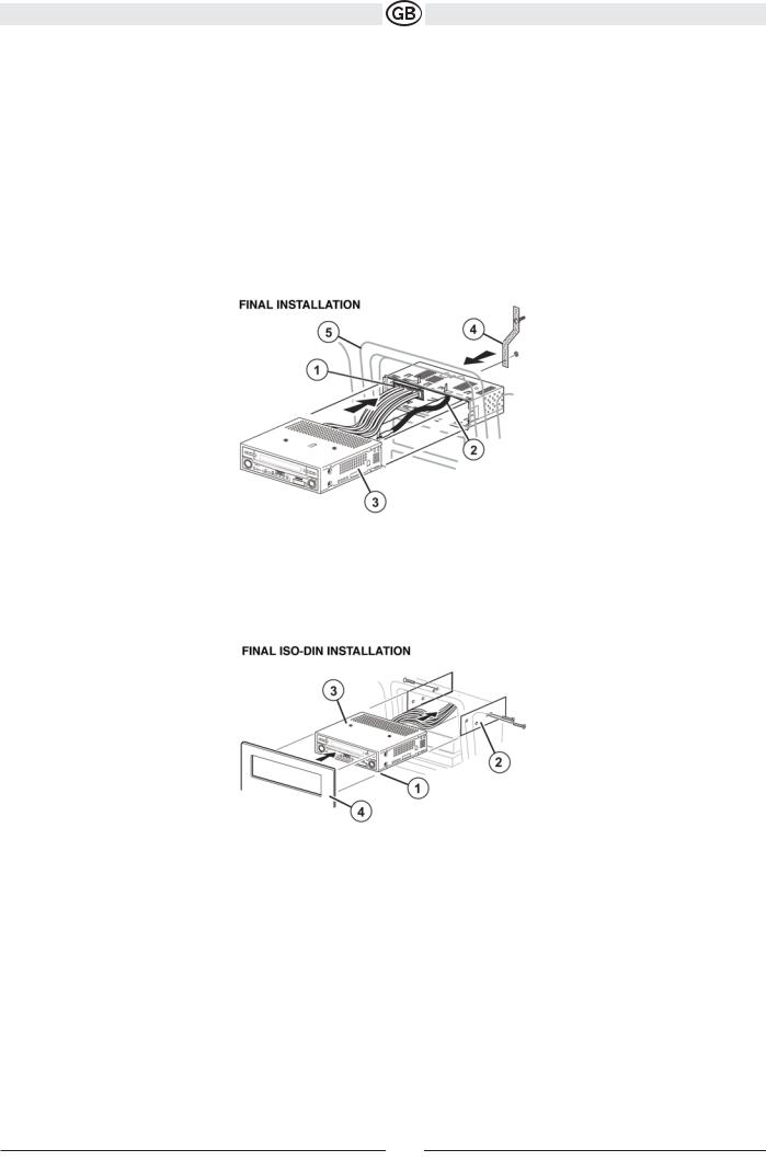
Final Installation
After completing the wiring connections, turn the unit on to confirm operation (ignition switch must be on). If unit does not operate, recheck all wiring until problem is corrected. Once proper operation is achieved, turn off the ignition switch and proceed with final mounting of the chassis.
1.Connect wiring adapter to existing wiring harness.
2.Connect antenna lead.
3. Carefully slide the radio into the half-sleeve, making sure it is right-side-up, until it is fully seated and the spring clips lock it into place
Subject to technical changes
59
NOTE:
For proper operation of the CD/DVD player, the chassis must be mounted within 20° of horizontal. Make sure the unit is mounted within this limitation.
4. Attach one end of the perforated support strap (supplied) to the screw stud on the rear of the chassis using the hex nut provided. Fasten the other end of the
perforated strap to a secure part of the dashboard either above or below the radio using the screw and hex nut provided. Bend the strap to position it as necessary.
CAUTION! The rear of the radio must be supported witht he strap to prevent damage to the dashboard from the weight of the radio or improper operation due tovibration.
5. Replace any items you removed from the dashboard.
Final ISO-DIN Installation
1.Remove trim ring.
2.Mount factory brackets on new radio using existing screws from old radio.
3.Slide radio chassis into dash opening and secure.
4.Reinstall dash panel.
Subject to technical changes
60

Important!
ANTI-THEFT FEATURE
The VME 9512 TS is equipped with an anti-theft feature requiring the user to enter a password upon initial power on. The default user password is 012345 (6 digits). To change the anti-theft and RATINGS protection password, perform the following steps:
1.Press the  SETUP button (31) on the remote control or touch the button on the screen to enter the “SETUP” menu.
2.Touch RATING to view the “RATING” sub-menu. The
small "lock" icon will be “unlocked”.
3. Enter a new 6-digit password and press ENTER. The "lock" icon will lock and the new anti-theft password will be set, as well as the password for RATING protection (see “Rating Sub-menu Features” on page 74).
Subject to technical changes
61
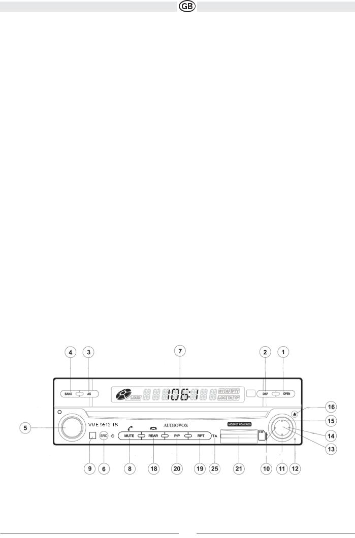
CONTROLS AND INDICATORS Button Operation
1. OPEN/CLOSE
Press to activate the automatic mechanical system and move the TFT monitor into viewing position. Press again to close the TFT.
2. DISP
With the TFT monitor open, press to cycle through information available on the TFT screen. With the TFT monitor closed, press and hold to view the clock.
In DVD Mode, press to view the top and bottom information bars. Press again to turn “Display Off”.
3. AS
Press to automatically store the first six strong stations in preset memory. Applies to current band only.
4. BAND
Press the BAND button to change the AM or FM band.
5. AUDIO
Rotate to adjust the volume. Press to enter and/or confirm audio settings.
6. SRC
Press to select playing mode.
7.LCD Display
8.MUTE
Press to silence the receiver. Press again to resume previous volume level.
BT Mode: Answer Bluetooth call.
NOTE: The VME 9512 TS features Softmute, which will allow the volume to increase or decrease gradually when the MUTE function is activated or deactivated.
9.IR Remote Control Receiver
10.(left joystick)
DVD/Disc Mode: Press once to play back the previous chapter/track. TUNER Mode: Press once to auto-search for the previous
available radio station.
MENU Mode: Press once to move the cursor to the left.
11. (down joystick)
DVD/Disc Mode: Press once for slow forward/slow reverse. TUNER Mode: Press to go down one frequency step. MENU Mode: Press once to move the cursor down.
NOTE: Only CINEMA and Standby are available for nonvideo sources. 12. Reset
Press to reset system settings to factory default (except the password and parental lock setting).
Subject to technical changes
62
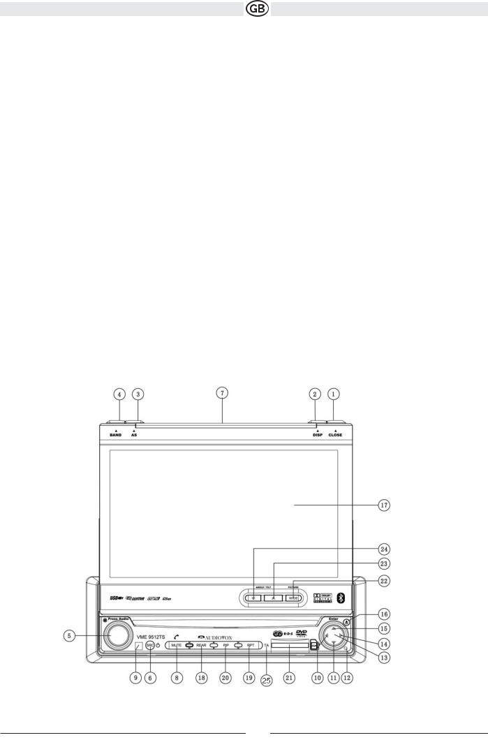
13.Pause/Play/Enter
Press to pause or resume playback or to confirm current selection. 14. (right joystick)
DVD/Disc Mode: Press once to enter the next chapter or track. TUNER Mode: Press once to auto-search the next available radio station. MENU Mode: Press once to move the cursor to the right.
15.(up joystick )DVD/Disc Mode: Press once for fast forward/fast reverse. TUNER Mode: Press to go up one frequency step.
MENU Mode: Press once to move the cursor up.
16.(  ) Press once for disc insertion/ejection.Press and hold to reset core mechanism position.
17.TFT Display
18.REAR
Select rear zone source. Allows front passengers to listen to the radio while rear passengers listen to a CD, MP3, WMA or watch DVDs.
BT Mode: Disconnect Bluetooth call.
19. RPT
Press to control repeat playback function.
20. PIP
Activate Picture In Picture feature.
21. SD Card Slot
Insert SD card for playback of media files.
22. WIDE
Press to adjust the display aspect of the picture to one of two settings: CINEMA, NORMAL or Standby (screen off)
NOTE: Only CINEMA and Standby are available for nonvideo sources.
Press and hold to adjust Brightness and Contrast.
23/24. ANGLE/TILT
Press to activate the tilt function. Press once to adjust the downward tilt angle of the screen one step at a time or press and hold to adjust the angle in a continuous motion up or down.
25. TA Long press to activate / deactivate the Traffic announcement
Subject to technical changes
63
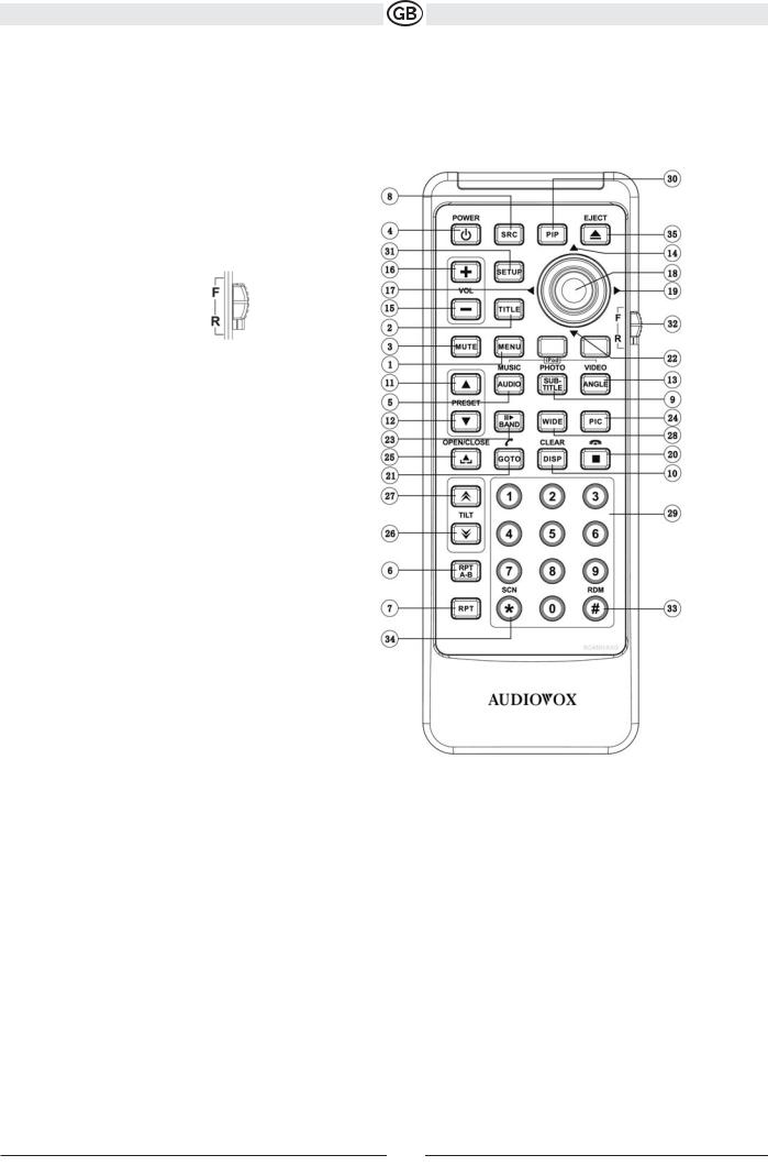
REMOTE CONTROL
The VME 9512 TS Remote controls both the front and rear zones. To switch from front to rear zone, move the F/R switch (32) located on the right side of the controller.
NOTE: Your remote control may differ slightly from the one pictured here. The above diagram is for illustrative purposes only.
Subject to technical changes
64

65
Subject to technical changes
 Loading...