


LCM7020PKG
®
ELECTRONICS CORP .
LCM7020PKG Two 7" Monitors with
Two Audio/Video Input Capability Mounted
in Vehicle Specific Headrests
POWER SOURCE W IDE MENU VOLUME
POW ERSOURCE WIDE PICTURE VOLUME
Installation and Operation Manual

IMPORTANT
An LCD panel and/or video monitor may be installed
in a motor vehicle and visible to the driver if the LCD
panel or video monitor is used for vehicle information, system control, rear or side observation or navigation. If the LCD panel or video monitor is used for
television reception, video or DVD play , the LCD panel
or video monitor must be installed so that these features will only function when the vehicle is in ‘park’
or when the vehicle’s parking brake is applied.
An LCD panel or video monitor used for television
reception, video or DVD play that operates when the
vehicle is in gear or when the parking brake is not
applied, must be installed to the rear of the driver’s
seat where it will not be visible, directly or indirectly,
to the operator of the motor vehicle.
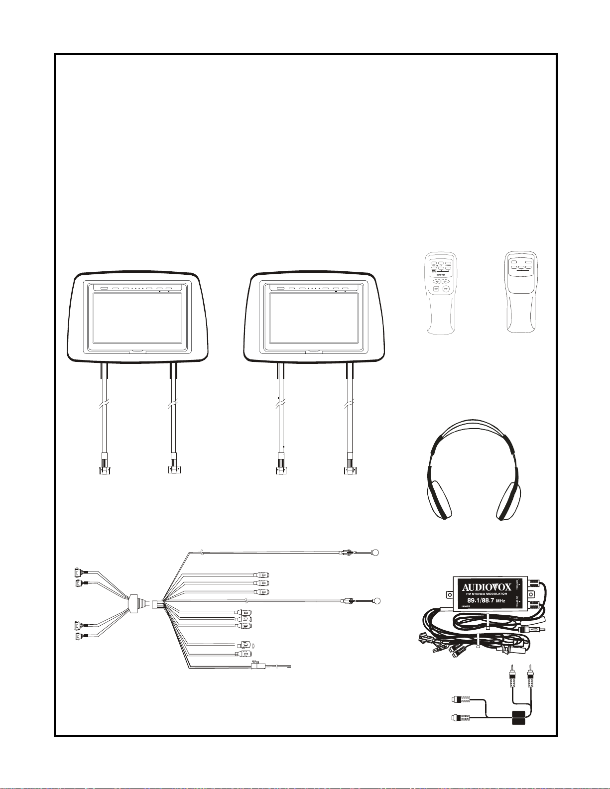
The Materials included in this package
S
S
S
1. LCM7020PKG System Monitor
(One Master-#LCM7020M, One Slave-#LCM7020S) (2pcs)
2. Master Remote Control Unit (MRCU)#136B3439 (1pc)
3. Slave Remote Control Unit (SRCU) #136B3440 (1pc)
4. System Main Cable (SMC) #1123277 (1pc)
5. Dual Frequency IR Headphone set (#IR2CHS) (2pcs)
6. FM Modulator package (#FMM100/IST2) (1set)
1.
Master Monitor
POWER SOURCE WIDE MENU
2.
lave M onitor
VOLUM E
POWER SOURCE WIDE PICTURE
VOLUME
3.
LCD
OURCE
POWER
+–
MENU/
ENTER
LAVE
5.
4.
6.
-1-
LCM7020PKG SYSTEM OVERVIEW
1) The LCM7020PKG is a versatile audio/video system which includes two monitors, that can accept
two Audio/V ideo inputs. A separate audio output is provided for connecting the FM Modulator to the
vehicle's radio.
2) The Master Monitor is comprised of a 7" TFT LCD monitor that allows the user to select from two
A/V sources (Not Supplied). The Master monitor has built-in infrared audio transmitter (CH A) for
use with the supplied two channel wireless headphones (CH A). The master monitor also has the
ability to select either audio source for output to the FM Modulator to allow audio playback through
the vehicle radio. The built in IR repeater circuitry enables the user to control the sources via
remote control.
(NOTE: The VCP functions on the master remote are for use with Audiovox products only.)
3) The slave monitor is identical to the Master Monitor, except that it can not select the audio for the
FM Modulator.
4) The monitors will show all of the functions including the FM selection (Master Only) with the comprehensive OSD.
5) The LCM7020PKG System supplies two IR Headphone sets (Audiovox IR2CHS). The headsets
have an A-B switch that allows the user's to select the audio from either the Master (CH A) or the
Slave (CH B).
6) Using different IR codes, the Master Monitor will only respond to the Master Remote Control unit
and the Slave monitor will respond only to the Slave Remote Control unit. Each operates independently of the other.
(NOTE: The IR Repeater in this system may not work with non-Audiovox components.)
7) There is a 1/8" headphone jacks on the LCM7020M & LCM7020S that can be used with any standard wired stereo headphones. These jacks are controlled by the volume up/down buttons on the
LCM7020M & LCM7020S remote control.
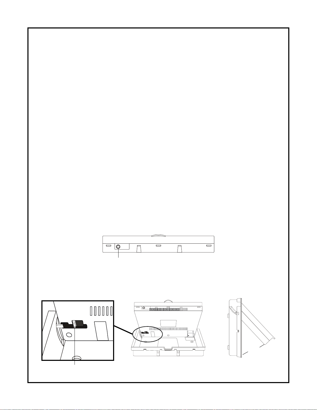
FRONT P ANEL
headphone jack
8) Pivot the screen until a comfortable viewing angle reached. The internal lock limits the screen to a
maximum adjustment of 30 degrees from closed position.
Internal Lock
30 degrees
-2-

VEHICLE PREPARATION:
1) Decide on the system configuration and the options that will be installed (i.e.what components,
VCP, DVD, TV Tuner , Video Game, FM Modulator , etc.).
2) Read the manuals and get familiar with the electrical requirements and connections.
3) Decide on the mounting locations and methods of mounting the products that will be connected to
the LCM7020PKG.
4) Prepare the vehicle by removing any interior trim necessary to gain access to the vehicle's wiring
as well as all areas where interconnecting wire harnesses will be located. (Refer to the Installation
Procedure). The mounting method, and the location will vary from vehicle to vehicle, so this manual
will only focus for the installation of the LCM7020PKG Master and Slave Monitors in the supplied
configuration. The best location for the LCM7020PKG System components is:
a. Monitors : Headrest (Vehicle specific)
b. FM Modulator: Near the car radio with the ON/OFF switch mounted on the
dash board near the driver.
c. System Main Cable: Under either seat where monitors are located.
5) Locate an accessory power source (+12VDC present when the ignition key is in the accessory and
run positions. 0VDC should be present, when the ignition key is in the OFF position). Generally,
these wires can be found at the ignition switch or fusebox. (NOTE: Ensure that the accessory
power is fused at the source. Failure to do so may result in vehicle wiring damage.)
6) Run the wiring harnesses throughout the vehicle as necessary. (Refer to the Wiring Diagrams on
page 7, as well as the wiring instructions for the individual components and accessory options
being installed). Be sure, that all the wiring is protected from sharp edges and is routed in such a
manner that it will not be pinched, when it is fully installed. Be sure to leave enough slack in the
wiring at each component to allow sufficient working room. Be sure to leave enough slack in the
monitor cables to allow the headrest to move up or down.
7) Remove all the A/V system components from their packaging and then place them in the vehicle at
their respective locations.
8) Install the Headrests:
a. Remove vehicle’s original Headrests.
b. Hold the LCM7020PKG Headrest above the seat and insert the two cables into the
headrest support tube holes. Make sure that the headrest is in the correct position (Dis-
play facing the rear).
c. Route the cables through the seat back and out the bottom of the seat.
d. Place the Headrest support tubes into the support tube holes while pulling the cables to
remove the slack. Be sure to leave enough slack in the monitor cables to allow the
headrest to move up or down.
e. Slide a few inches of each cable through the Black Shrink Sleeve (see
f . Carefully remove Clear Shrink Tubing making sure not to damage wires inside.(see
g. Separate and straighten all of the wires.
h. Carefully insert each of the Terminal Pins into the Terminal Connector making sure that
each color wire is placed into the matching color connector hole. (see
i. Slide the
9) Connect all the components together (electrically) and verify that the proper operation of all the system
functions. NOTE: This is best done BEFORE the components are permanently mounted.
10) After verifying the proper operation of the system, proceed to mount each component.
1 1 ) When all the components are mounted, re-check the entire system to be sure it is functioning correctly.
Make sure that no wiring was pinched, or connected improperly during the final installation.
Black Shrink Sleeve down over the wires and apply heat (hot air).
2)
1)
3)
-3-
 Loading...