


FRS-1000F

FRS/ WeatherFRS/ Weather
FRS/ WeatherFRS/ Weather
FRS/ Weather
Model:Model:
Model:Model:
Model:
FRS-1000 FRS-1000
FRS-1000 FRS-1000
FRS-1000
Base Station With NOAA Weather AlertBase Station With NOAA Weather Alert
Base Station With NOAA Weather AlertBase Station With NOAA Weather Alert
Base Station With NOAA Weather Alert
OwnerOwner
OwnerOwner
Owner
’s Man’s Man
’s Man’s Man
’s Man
ualual
ualual
ual
Customer Service/Service
1-800-290-6650
© 2001 Audiovox Electronics Corp., Hauppauge, NY 11788

NEVER ATTEMPT T O CHARGE ALKALINE OR DRY CELL BATTERIES.
WHEN RECHARGING, USE ONL Y THE RECHARGEABLE BATTERIES
SUPPLIED WITH YOUR TRANSCEIVER. USE OF OTHER BATTERIES
WILL CAUSE DAMAGE TO YOUR FRS-1000 WEA THER RADIO TRANS-
CEIVER. OTHER TYPES OF BATTERIES MAY BURST CAUSING PER-
SONAL INJURY.
A VOID INSTALLING THE FRS-1000 TRANSCEIVER IN AN AREA WHERE
IT MAY BE SUBJECTED FOR PROLONGED PERIODS OF TIME TO DI-
RECT SUNLIGHT OR TEMPERATURES BELOW -4° F (-20° C) OR
ABOVE 140 ° F (60° C).
KEEP THE ANTENNA A T LEAST 1 INCH (2.5 cm) AWAY FROM YOUR
HEAD AND BODY. DO NOT USE YOUR FRS-1000 RADIO TRANS-
CEIVER WITH A DAMAGED ANTENNA.
Family Radio Service:
The Family Radio Service (FRS) 2-way base (fixed) station “transceiver”
(“transmitter and receiver”) radio has been designed for family and friends
to keep in touch without the need for a license.
It provides safety and convenience indoors for two-way radio operation
between home base and other mobile FRS units, and operates on Family
Radio Service designated frequencies.
The FCC has established the license free, short -range two- way radio service
for family and individual recreational use.
The optimal range for this 2-way radio is approximately 2 miles in open
areas; less in areas with buildings, dense foliage, and mountains.
CAUTION
2
3
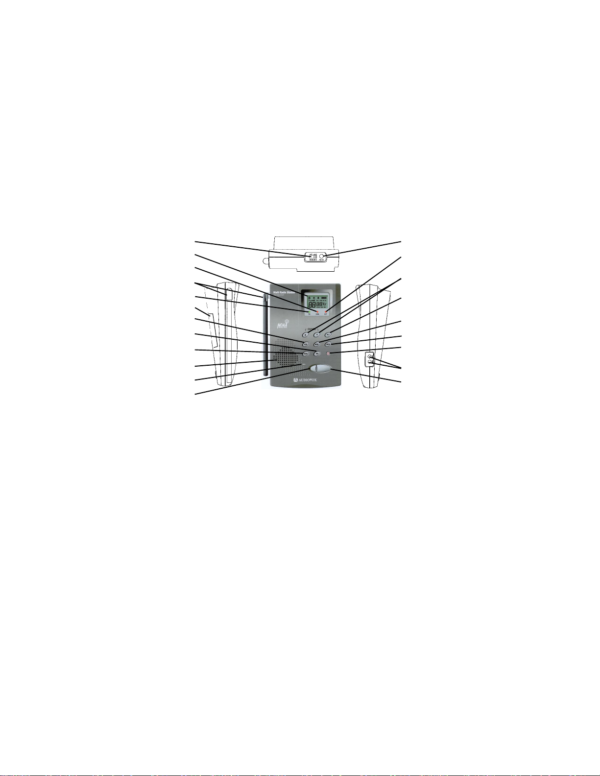
1. Battery CHARGE On/Off Switch
2. Liquid Crystal Display (LCD)
3. Alert (ALT) LED (Red)
4. Antenna (Retractable)
5. Transmit LED (Green)
6. Battery Door
7. Voice-Operated Transmission
(VOX) Button
8. Weather/FRS Button
9. SCAN/Lock Button
10. Built-in Speaker
11. Built-in Microphone
Model FRS-1000
12. CALL Button
13. DC12V Power Jack
14. Charging (CHG.) LED (Red)
15. Up/Down Channel/Volume Buttons
16. Weather Alert Button
17. MODE Button
18. LCD Backlight/Monitor (L/MON)
Button
19. Power On/Off and Function Set
Button
20. External Speaker(SPK)/Micro-
phone (MIC) Jacks
21. Push-To-Talk (PTT) Button
15
6
18
8
20
5
4
21
10
11
2
17
9
7
12
19
16
14
13
1
3
4
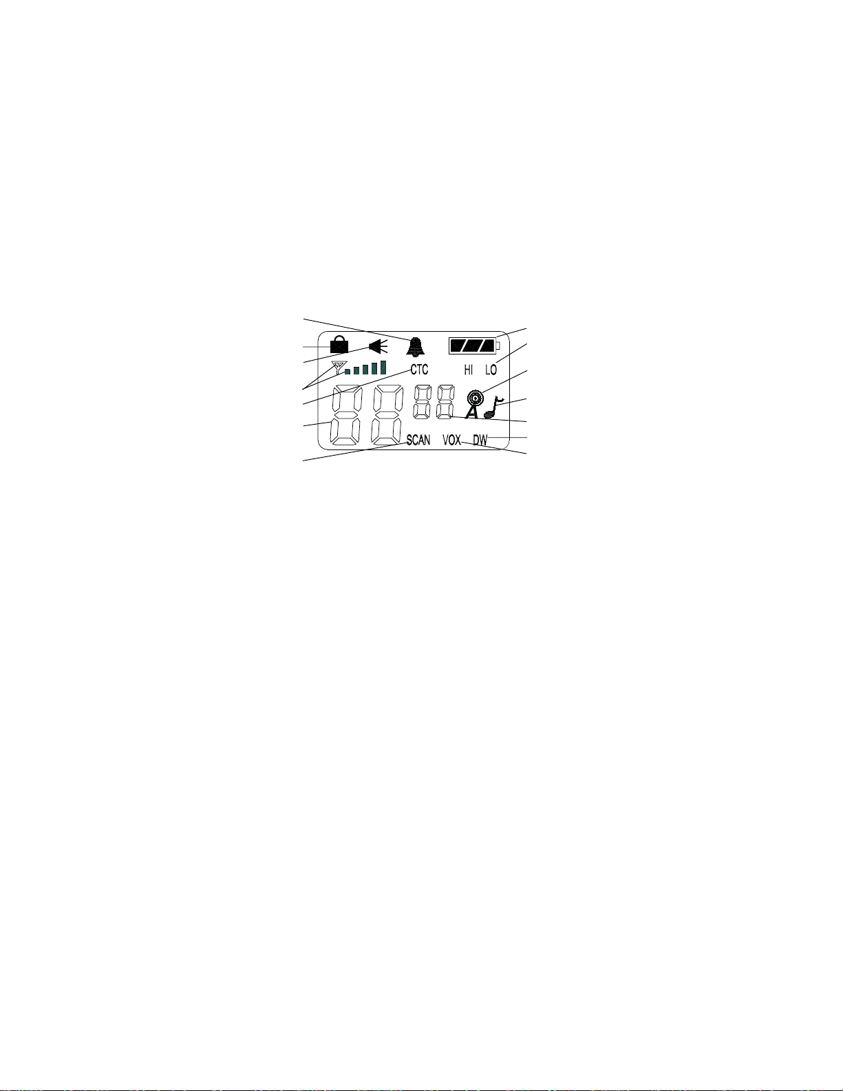
Model FRS-1000 DISPLAY
1. Button (Key) Tone Beep On/Off Indicator: This icon appears
when the beep key tone is on, and disappears when tone is not
in use.
2. Key Lock Indicator: Icon appears when keypad is locked. This
function disables keys such as channel up/down and MODE.
3. Monitor Indicator: Icon appears when the Monitor (L/MON)
button is pressed and the channel monitor function is activated.
4. Signal Strength Indicator: Icon appears when a signal is being
received. The icon consists of five bars to indicate the received signal
level. The icon also represents transmit signal power when
transmitting.
5. Continuous Tone Coded Squelch System (CTCSS) Indicator:
Icon appears when the CTCSS tone function is active.
6. Large Segment Display: Indicates the FRS channel number in
use.
7. Scan Indicator: This function allows the user to scan a channel
and/or a tone code every .5 second to search for a valid signal.
8. Battery Level Indicator: Icon indicates the battery charge level.
9. HI/LO Indicators: Appropriate icon appears when the transmit
power is set to desired output power.
12
11
10
13
14
7
8
6
4
5
3
2
1
9

5
10. Weather Mode Indicator: Icon appears steady when weather
mode is active; it flashes when weather alert is active in the FRS
mode.
11. Roger Beep Tone Indicator: Icon appears when the roger beep
tone is enabled, signifying transmission has been terminated. Icon
disappears when tone is disabled.
12. Small Segment Display: Displays the CTCSS tone option for a
given channel from (01-38).
13. Dual Watch Mode Indicator: Icon appears when dual watch mode
is active.
14. Voice Activated Transmission (VOX) Indicator: This function
allows hands-free conversation. The icon appears when the VOX
mode is activated.
Powering the transceiver:
The primary power source for Your FRS-1000 base station is the AC wall
adapter. The FRS-1000 is also supplied with a battery back-up, should you
experience loss of household current. The FRS-1000 will automatically switch
to battery back-up when AC power is interrupted. The rechargeable
batteries, Part Number FRSRBAT, are charged in the radio transceiver
using the AC power adapter, which is also supplied with the unit.
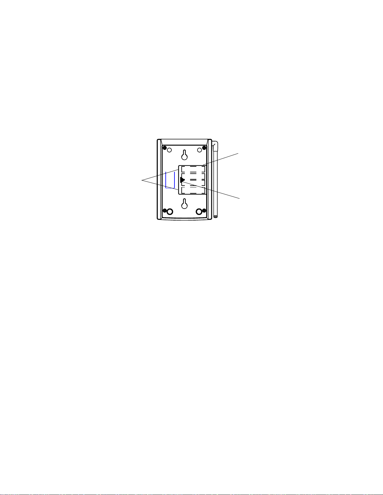
Installing the Back-Up Batteries:
The four AA batteries are installed in the compartment at the right rear of
the transceiver; the compartment is fitted with a removable cover. Install
the batteries as follows:
1.Press down with the thumb at the arrow, and slide the battery cover off
the side of the unit.
2. Insert the four AA rechargable batteries, Part Number FRSRBAT,
provided. (Alternate positive ends (+) as shown in battery compartment
layout.) Replace the cover.
6
The following guidelines will improve performance and provide longer
operating times for the FRS-1000:
1. Do not mix old and new batteries.
2. Do not mix alkaline, standard (carbon-zinc) or rechargeable
(Ni-MH)batteries.
3. If the unit is not to be used for an extended period of time, remove the
batteries. Old or leaking batteries can cause damage to the unit and will
void the warranty.
Charging FRS-1000 Batteries P/N FRSRBA T :
The rechargeable batteries, Part Number FRSRBAT, supplied with the
unit, are charged by connecting the AC Adapter plug to the DC12V jack on
the top of the unit, and setting the CHARGE switch to the ON position. Use
only the AC Wall Adapter, Part Number FRS1-AD, that is supplied with the
base unit. The CHG. LED indicator below the LCD display lights
red
during
battery charge operation.
BATTERY
INSTALLATION
POLARITY
+
+
-
-
BATTERY
COMPARTMENT
COVER
BATTERY
COMPARTMENT
COVER ARROW

The battery charge indicator icon displays the battery charge level when the
AC adpter is unplugged. When the AC adapter is connected and in use, the
indicator icon will indicate a full charge as shown below.
Full Battery - three segments are illuminated.
Low Battery - one segment is illuminated.
Approximately 20–24 hours are required to fully charge the batteries. The
red LED charging indicator (14) will light whenever the batteries are
charging. A flashing red LED charging indicator denotes batteries are not
installed. You must set the CHARGE switch to the OFF position, when
using any batteries other than the ones provided. Failure to do this may
cause damage to batteries resulting in personal injury and/or damage to
the unit.
Caution: The charging adapter is intended for use with the supplied
rechargeable Ni-MH batteries Part Number FRSRBAT. Do not
attempt to recharge any other type batteries.
7
CHARGE
ON/OFF
SWITCH
AC
ADAPTER
ADAPTER
PLUG
BASE
UNIT
DC12V
JACK

8
NOTE:
To switch between FRS and Weather Band modes, momentarily press the
FRS/WX button. To differentiate between operating modes, look for HI or
LO indication below the battery power level indicator when in FRS mode.
In Weather Band mode, these indications are not present. Refer to the
appropriate section of this manual for detailed operating instructions
for each mode.
FRS-1000 OPERA TIONAL MODES
CHANNEL SELECT
(WX/MODE/CH)
WEA THER BAND
BUTTON BEEP
(WX/MODE,MODE/
On/oF)
CHANNEL
SELECT
CALL
SELECT
FRS BAND
CTCSS
SELECT
POWER
SELECT
DUAL
WATCH
ROGER
BEEP
KEY TONE
 Loading...