


®

 CCS-100
ELECTRONIC CRUISE CONTROL INSTALLATION MANUAL
INDEX |
|
|
Page |
1.CruiseControlInstallation:..................................................... |
1 |
PartsList........................................................................... |
2 |
ThrottleConnections......................................................... |
3 |
Wiring............................................................................... |
4 |
2.ControlSwitchInstallation...................................................... |
8 |
Troubleshooting............................................................... |
9 |
3.MagnetKitInstallation............................................................. |
12 |
SpeedSensorInstallation................................................ |
13 |
4.Warranty................................................................................... |
16 |
MANUAL PREPARED AND PROVIDED BY LITEON AUTOMOTIVE CORPORATION

HOW THE CRUISE WORKS
The Cruise Module makes "decisions" based upon speed,tachometer, and brake signal information. The control circuit interprets digital speed information from the car's engine control module (VSS) or Magnet Kit and ignition coil output. Brake information comes from the red and purple wires connected to the vehicle's brake switch. Disengagement and no-engagement decisions are based on the monitored information.
An integral part of the cruise is the 'over rev.' protection circuit. It's function is to monitor engine R.P.M. and disengage the cruise control when the clutch is applied or the transmission shift lever is moved in to neutral. When a sudden rise in R.P.M. is detected, the decision to disengage is made for 'over rev' protection, the blue wire must be attached to the negative side of the ignition coil. A noise suppressor 'in series' with the blue wire keeps excessive electrical noise from "fooling" the cruise into disengaging. For this reason make sure all cruise control wiring is at least 1 ft. away from all electromagnetic sources such as: ignition wires, alternator, regulator, and all high current carrying conductors.
NOTE : If your vehicle is not listed in the enclosed reference manual, the Magnet Kit must be utilized. Additional available options: CCS-202 Vacuum Reservoir and CCS-204 Ford adaptor.
WARNING : WHEN TESTING WIRES, USE ONLY A LOGIC PROBE OR VOLT / OHM METER. DO NOT USE A TEST LIGHT, AS THESE CAN CAUSE DAMAGE TO THE ECM OR MAY ACTIVATE THE AIRBAG!
WARNING : DO NOT ATTEMPT TO ROAD TEST ON JACK STANDS OR A LIFT !
CAUTION : BEFORE DRILLING ANY HOLES, BE SURE THAT NO COMPONENTS WILL BE DAMAGED AFTER THE DRILL PENETRATES THE SURFACE.
CAUTION : DO NOT MOUNT OR ROUTE WIRING HARNESSES OR KIT COMPONENTS ON OR NEAR ANY HOT, SHARP, OR MOVING SURFACES WITHIN THE VEHICLE.
NOTE : IF YOU DO NOT FEEL CONFIDENT THAT YOU CAN SAFELY INSTALL THE CRUISE CONTROL BY YOURSELF, THEN WE RECOMMEND THAT YOU HAVE IT INSTALLED BY A QUALIFIED PROFESSIONAL.
Required Tools |
|
|
|
1. |
Digital Volt OHM meter or logic probe |
4. |
Pliers |
2. |
Drill with the following size bits : 1/4" & 1/2" |
5. |
Side cutter pliers |
3. |
#2 Phillips screwdriver |
6. |
Small wrench or socket set |
It is important that you read and fully understand this entire instruction manual before proceeding with the installation. Pay close attention to all cautions and warnings contained in this manual for a safe and trouble free installation.
-1-

PARTS LIST
Servo Assembly |
M6 external tooth |
Dash Mounted control switch |
Tie Straps |
1/2" rubber bulkhead |
|||
( 1 ) |
star washer |
|
( 1 ) |
|
|
( 10 ) |
grommet |
|
( 3 ) |
|
|
ACC |
|
|
( 1 ) |
|
|
ON |
CRUISE |
RES |
|
|
|
|
|
OFF |
CONTROL |
SET |
|
|
|
|
|
AUDIOVOX |
CST |
|
|
|
|
- 1 - |
- 2 - |
|
- 3 - |
|
|
- 4 - |
- 5 - |
Convoluted tubing |
Vacuum hose reducing |
Assorted Vacuum |
|
Vacuum Hose - Short |
Vacuum Hose - Long |
||
( 1 ) |
nipple |
T - Connectors |
|
( 1 ) |
( 1 ) |
||
|
( 1 ) |
|
|
|
|
|
|
- 6 - |
- 7 - |
|
- 8 - |
|
|
- 9 - |
- 10 - |
Main Wiring Harness |
Fused wire with switch |
Scotch lock connectors |
Female T- tap terminal |
“L” Bracket |
|||
( 1 ) |
connector |
|
( 4 ) |
|
|
( 1 ) |
( 1 ) |
|
( 1 ) |
|
|
|
|
|
|
- 11 - |
- 12 - |
|
- 13 - |
|
|
- 14 - |
- 15 - |
Adjustable cable |
Assorted tube clamps |
Parallel throttle cable |
|
GM style threaded |
Bead chain |
||
mounting bracket assy. |
(4) |
|
clamps |
|
|
snap in cable anchor |
( 1 ) |
( 1 ) |
|
|
( 1 ) |
|
|
( 1 ) |
|
- 16 - |
- 17 - |
|
- 18 - |
|
|
- 19 - |
- 20 - |
Cotter pin |
Ford snap on throttle |
Bead chain coupling |
|
Bead chain coupling |
Bead chain eyelet |
||
( 1 ) |
adaptor |
|
sleeves |
|
|
( 2 ) |
connector |
|
( 1 ) |
|
( 2 ) |
|
|
|
( 1 ) |
- 21 - |
- 22 - |
|
- 23 - |
|
|
- 24 - |
- 25 - |
GM throttle clip |
3 bead connector |
Throttle mounting |
|
Throttle wire loop |
Barrel wire adaptor |
||
( 1 ) |
( 1 ) |
bracket with locking |
|
( 1 ) |
( 1 ) |
||
|
|
|
washer |
|
|
|
|
- 26 - |
- 27 - |
|
- 28 - |
|
|
- 29 - |
- 30 - |
M6 hex nuts |
M6 x 5/8" long |
M6 x 3/4" long hex |
Slotted head shoulder |
M5 Phillips hex head |
|||
( 3 ) |
hex head bolt |
washer head sheet |
|
bolt with lock washer |
bolt with hex nut |
||
|
( 3 ) |
metal screw |
|
|
and hex nut |
( 1 ) |
|
|
|
|
( 4 ) |
|
|
( 1 ) |
|
|
|
|
|
|
|
||
- 31 - |
- 32 - |
|
- 33 - |
|
|
- 34 - |
- 35 - |
|
|
|
-2- |
|
|
|
|
PROGRAMMING THE SERVO ASSEMBLY
To ensure that the cruise control operates smoothly and safely in your vehicle, the servo assembly must be programmed. In order to properly program the servo assembly, you will need to know the number of cylinders, the type of transmission (manual or automatic), if your vehicle is equipped with a Vehicle Speed Sensor (VSS), and if so, the number of Pulses Per Mile ( PPM ), also if the cruise control switch is the open or closed circuit style. The dash mount control switch supplied is the open circuit style switch. SW6 should be set to OFF.
Refer to the enclosed reference manual for information of VSS and PPM that applies to your vehicle. If there is no VSS signal in your particular vehicle then the Magnet Kit must be used. Mount one magnet to the drive shaft if the vehicle is rear wheel drive and set PPM to 2000. Mount 2 magnets to the drive shaft at 180° apart if the vehicle is front wheel drive and set PPM to 2000. Note: When using magnets set Dip Switch #3 to "ON". The sensitivity settings, control the amount of vacuum needed to keep the set speed constant. Remove the ( 2 ) screws securing the plastic cover on the back of the servo assembly to gain access to the dip switches. DIP SWITCH PROGRAMMING TABLE: Follow the chart below to program the servo assembly.
|
PPM |
|
SW1 |
SW2 |
SW3 |
SW4 |
SW5 |
SW6 |
SW7 |
|
|
|
|
|
|
|
|
|
|
2,000 |
|
OFF |
OFF |
|
|
|
|
|
|
4,000 |
|
ON |
OFF |
|
|
|
|
|
|
5,000 |
|
OFF |
ON |
|
|
|
|
|
|
8,000 |
|
ON |
ON |
|
|
|
|
|
|
|
SPEED SIGNAL |
|
|
|
|
|
|
|
|
|
TACH ONLY |
|
|
OFF |
|
|
|
|
|
|
VSS or MAGNETS |
|
|
ON |
|
|
|
|
|
|
SENSITIVITY |
|
|
|
|
|
|
|
|
|
LOW |
(LIGHT VEHICLES W/HIGH HORSE POWER) |
ON |
OFF |
|
|
|||
|
MEDIUM (MOST VEHICLES) |
|
|
OFF |
OFF |
|
|
||
|
HIGH (LOW POWER VEHICLES/HEAVY VEHICLES) |
OFF |
ON |
|
|
||||
|
CONTROL SWITCH |
|
|
|
|
|
|
|
|
|
NORM. CLOSED |
|
|
|
|
|
ON |
|
|
|
NORM. OPEN |
|
|
|
|
|
OFF |
|
|
|
TACH SOURCE SELECT |
|
|
|
|
|
|
|
|
|
ECM |
|
|
|
|
|
|
|
OFF |
|
COIL |
|
|
|
|
|
|
|
ON |
* When changing dip switch setting, make sure the 10-pin connector is unplugged from module.
MANUAL / AUTOMATIC TRANSMISSION SELECT
WHEN INSTALLING THIS KIT INTO VEHICLES THAT HAVE A MANUAL TRANSMISSION, YOU MUST REMOVE THE BLACK JUMPER CONNECTOR LOCATED TO THE LEFT SIDE OF DIP SWITCH #1. NOTE: If the vehicle is a manual transmission and does not have a VSS wire, the cruise will operate from tach signal only. Program dip switch #1 and #2 for 4000 PPM and move dip switch #3 to OFF position.
|
|
|
|
|
|
|
ON |
|
|
|
|
|
|
|
|
|
|
|
||
LED |
|
|
|
|
|
OFF |
|
|
|
|
|
|
|
|
|
|
|
|||
|
|
|
|
1 2 |
3 |
|
4 |
5 |
6 |
7 |
|
|
|
|||||||
|
|
|
|
|
|
|
||||||||||||||
JUMPER |
|
|
|
|
|
|
|
|
|
|
||||||||||
|
|
|
|
|
|
|
|
|
|
|
|
|
|
|
|
|
|
|
|
|
|
|
|
|
|
|
|
|
|
|
|
|
|
|
|
|
|
|
|
||
|
|
|
|
|
|
|
|
|
|
|
|
|
|
|
|
|
|
|
|
|
|
|
|
|
|
|
|
|
|
|
|
|
|
|
|
|
|
|
|
|
|
#1 - BROWN - IGNITION POWER |
|
|
|
|
|
|
|
|
|
|
|
|
|
|
|
#10 - BLUE - TACH. |
||||
#2 - GREY - SPEED |
|
|
|
|
|
|
|
|
|
|
|
|
|
|
|
#9 - BLACK - GROUND |
||||
#3 - RED - BRAKE |
|
|
|
|
|
|
|
|
|
|
|
|
|
|
|
#8 - GREEN - SET |
||||
#4 - PURPLE - BRAKE |
|
|
|
|
|
|
|
|
|
|
|
|
|
|
|
#7 - (NOT USED) |
||||
#5 - (NOT USED) |
|
|
|
|
|
|
|
|
|
|
|
|
|
|
|
#6 - YELLOW - RESUME |
||||
|
|
|
|
|
|
|
|
|
|
|
|
-3- |
|
|
|
|
|
|
||
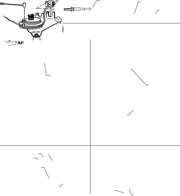
UNDER HOOD INSTALLATION
Connecting the Cruise Control Cable to the Throttle
NOTE: Prior to attaching servo cable to throttle, locate an accessible area to mount the cruise control servo, but do not mount it. Leave the servo in this area (unmounted) and route cable to throttle attachment area.
CAUTION: Attach the cruise control cable so that it parallels the existing throttle cable as nearly as possible.
Choose a mounting method from the figures below:
FIG. 1
The bead chain and servo cable end must be inserted into the bead chain connector. Then the bead chain coupling sleeve must slide over bead chain connector to insure that the end will not hang in the connector.
Bead Chain |
Attachment area for |
|||
Coupling Sleeve (#23) |
||||
securing cable |
||||
|
|
|
||
|
|
|
Cable |
|
|
|
Bead Chain Coupling (#24) |
||
|
|
|||
|
|
|||
Determine a suitable point on the throttle linkage to mount the cable connector. The mounting point chosen should have between
1-1/2" to 2" total linkage travel. It must operate smoothly by hand. There should be at least 5 beads between the throttle connector and servo cable end. The cable must pull in a straight line from throttle linkage. Some vehicles that do not have enough total linkage travel have to be connected at the accelerator pedal.
FIG. 2 |
|
|
SNAP-ON THROTTLE ARM MOUNT |
FIG. 3 |
CLAMP-ON THROTTLE ARM MOUNT |
|
Existing Snap-On Throttle Arm On Vehicle |
||||||
|
|
|
||||
Carburetor |
|
|
|
|
Cable Must Be within 20° of |
|
|
|
|
|
|||
|
|
|
|
|
same angle as Throttle Rod |
|
|
|
|
|
|
20° |
|
|
|
|
Bead Chain Eyelet |
|
|
|
|
|
|
Connector (#25) |
|
|
|
Pull off Throttle Arm and Insert Bead Chain Connector between it |
|
Bead Chain Eyelet |
||||
and Carburetor Arm. Be sure additional thickness of adaptor does |
|
|||||
|
Connector (#25) |
|||||
not bind linkage. |
|
|||||
|
|
|||||
|
|
|
|
|
|
|
FIG. 4 |
|
|
WIRE LOOP FOR PULLEY |
FIG. 5 |
WIRE BARREL FOR PULLEY |
|
|
|
Rubber Ring |
|
|||
|
|
|
|
|
||
|
|
|
Throttle Wire Loop |
Barrel Wire Adaptor |
||
|
|
|
(#30) |
|
||
|
(#29) |
|
||||
|
|
|
||||
|
|
|
Throttle Cable |
|
|
|
FIG. 6 |
3 BEAD CONNECTOR |
FIG. 7 |
FORD LINKAGE ADAPTOR |
|||||
|
|
|||||||
Double fold to shorten |
|
|
|
|
|
Cotter Pin (#21) locks Bead |
|
|
3 Bead Connector |
|
|
|
|
|
|
||
|
|
Crimp with pliers |
Chain to Linkage Adaptor |
|
||||
(#27) |
|
|
|
|||||
|
|
|
|
|
||||
|
|
|
|
|
|
|
|
|
Bend to clear Throttle Cable |
|
|
|
|||||
Throttle Arm |
|
|
|
|
|
|
|
|
|
|
|
|
|
Throttle Clip |
|
|
|
|
|
|
|
|
|
|
|
|
|
(#26) |
Bead Chain |
|
|
||||
|
Throttle Cable |
|
|
|||||
|
(#20) |
|
Snap-on Throttle Adaptor (#22) |
|||||
|
|
|
|
|
|
|
||
|
|
|
|
|
|
-4- |
|
|
 Loading...