


AS 9075

Model AS 9075
Installation Manual
Remote Start Upgrade Module
Installation Instructions
This Unit Is Intended For Installation In Vehicles With
12 Volt Negative Ground Electrical Systems,
Gasoline or Diesel With True Tach Reference
And Automatic Transmissions Only.
Kit Contents
AS-9075 Control Module
(1) - Multi Pin Input/Output Harness
(1) - Six Pin Power Harness
(1) - Four Pin Auxiliary Harness
(1) - Three Pin I/O Harness
(2) - 30 Amp In-line Fuse Holders With Fuses
(1) - Control Switch / Programming Switch
(1) - Ring Terminal
(4) - 1/2" Long Screws
(1) - Pin Switch
(1) - Remote Start Warning Label
(1) - Literature Package
1

The AS-9075 Remote Start/Keyless Entry System is designed to be used with Automatic Transmission
Vehicles Only! The unit provides a selectable ignition control that allows a 10 second output for glow plug
preheat whichmaybe required for certain diesel vehicles, (see selectable feature #5). If the diesel engine has
a instant fire, (no glow plug preheat system), feature #5 should remain in the default Gasoline mode setting.
For diesel applications, consult your dealer for the type of ignition system used in your particular vehicle.
Regardless of the vehicle, Gasoline or Diesel, for every installation, the vehicle MUST HAVE a Tach Signal
Output, and an Automatic Transmission.
INSTALLATION OF THE MAJOR COMPONENTS:
CONTROL MODULE:
Select a mounting location inside the passenger compartment (up behind the dashboard). The mounting
location selected must be within 24" of the ignition switch wiring harness to allow connection of the 6-pin
main wiring harness.
Be certain that the chosen location will not interfere with proper operation of the vehicle. Avoid mounting the
module to or routing the wiring around the steering shaft/column, as the module or wiring may wrap around or
block the steering wheel preventing proper control of the vehicle. Secure the module in the chosen location
using cable ties or screws as necessary.
Do Not Mount The Module In The Engine Compartment, as it is not waterproof.
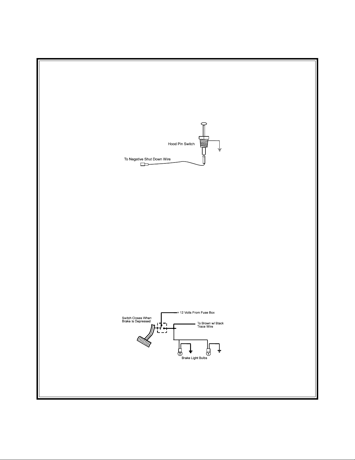
HOOD PIN SWITCH:
The pin switch included in this package is required for the safety shut down of the remote start unit. If the
vehicle is being worked on, this hood switch prevents the remote start activation even if the RF command to
start is issued. This switch MUST be installed in all applications Failure to do so may result in personal
injury or property damage. Mount the switch in an area under the hood that is away from water drain paths.
If necessary, the included brackets may be used to move the switch away from rain gutters or allow
mounting to the firewall behind the hood seal. In either case the switch must be set up to allow the hood door
to depress the switch at least 1/4 inch when the hood is closed and fully extended when the hood is opened.
For direct mounting, a 1/4 inch hole must be drilled. Carefully check behind the chosen location to insure the
drill will not penetrate any existing factory wiring or fluid lines. Drill a 1/4" hole in the desired location and
thread the pin switch into it using a 7/16" nut driver or deep well socket. If using the mounting bracket, first
secure the bracket to the desired location and secure the pin switch in the pre-threaded mounting bracket
hole.
PROGRAM SWITCH / CONTROL SWITCH:
Select a mounting location that is within reach of the ignition switch, as this switch, in combination with the
ignition switch and brake, will be used to program the selectable features of the system. It is suggested that
the switch be mounted to the lower dash panel in the driver's area. Inspect behind the chosen location to
insure that adequate clearance is allowed for the body of the switch, and also that the drill will not penetrate
any existing factory wiring or fluid lines. Drill a 1/4" hole in the desired location and mount the switch by
passing it through the panel from the underside. Secure the switch using the nut, star washer, and on/off face
plate. It is best to oriented the switch to allow the on position to be up toward the driver and the off position
to be down or away from the driver. Route the switch wires toward the control module.
The AS-9075 is to be used in vehicles with AUTOMATIC TRANSMISSIONS only! Although this Remote
Start unit is a sophisticated system with many advanced features, IT MUST NOT be installed into a vehicle
with a manually operated transmission. Doing so may result in serious personal injury and property damage.
IMPORTANT!
DO NOT PLUG THE SIX PIN MAIN POWER HARNESS OR THE MULTI PIN INPUT / OUTPUT HARNESS
INTO THE CONTROL MODULE UNTIL ALL CONNECTIONS TO THE VEHICLE HAVE BEEN MADE.
AFTER SELECTING YOUR TARGET WIRES AS DEFINED BELOW, DISCONNECT THE NEGATIVE
BATTERY CABLE FROM THE VEHICLE BATTERY PRIOR TO MAKING ANY CONNECTIONS.
2
Remote Start Connection
WIRING THE 6 PIN MAIN POWER HARNESS:
RED w/ WHITE Trace Wire: + 12 volts Battery 1 Source
Connect this wire toa+12VDCconstant source found at the vehicle's ignition switch using the 30 Amp fuse
and holder provided. This wire provides power for the control circuit as well as the ignition 1 and ignition 2
relays.
RED Wire: + 12 Volts Battery 2 Source
Connect this wire toa+12VDCconstant source found at the vehicle's ignition switch using the 30 Amp fuse
and holder provided, but NOT the same vehicle wire as used by the battery 1 source. Most vehicles have
more than one battery source supplying power to the ignition switch. Separate feed wires must be used for
the Red and Red/White wires. If your vehicle does not have two battery feed wires at the ignition switch then
it is possible to connect both wires to the vehicle's battery. This wire provides power for the start relay and the
accessory relay.
IMPORT ANT!
It is the responsibility of the installing technician to determine the load factor of the vehicles electrical circuits
when the vehicle is running and to adequately fuse the two power wires based on that load. If the vehicle,
running under load with the air conditioner, heater blower motor, and accessories exceed 24 Amps continu-
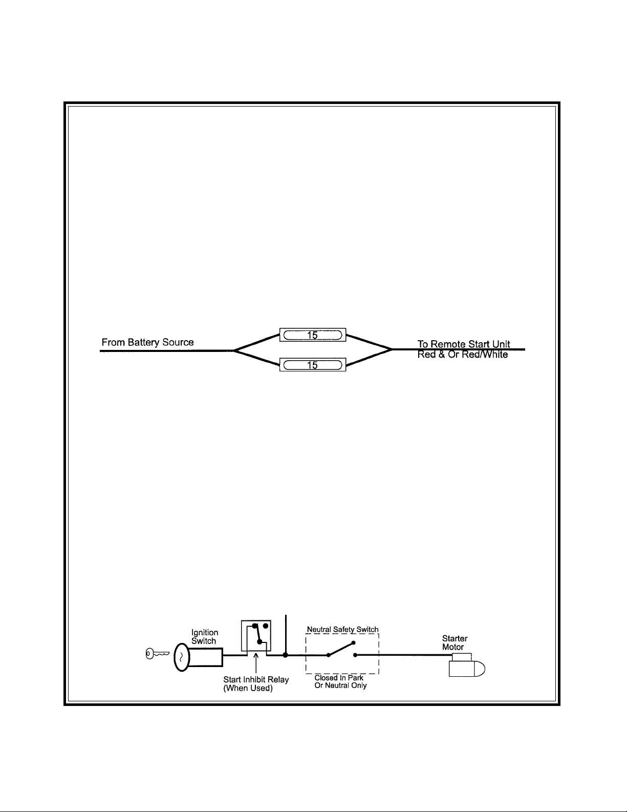
ous, we recommend that two fuses be used in combination on each power wire as shown below. For
additional information see Tech Update issued 9/30/96.
YELLOW Wire: Starter Output
Careful consideration for the connection of this wire must be made to prevent the vehicle from
starting while in gear. Understanding the difference between a mechanical and an electrical Neu-
tral Start Switch will allow you to properly identify the circuit and select the correct installation
method. In addition you will realize why the connection of the safety wire is required for all
mechanical switch configurations.
Failure to make this connection properly can result in personal injury and property damage.
In all installations it is the responsibility of the installing technician to test the remote start unit and assure
that the vehicle cannot start via RF control in any gear selection other than park or neutral.
In both mechanical and electrical neutral start switch configurations, the connection of the Yellow wire will be
made to the low current start solenoid wire of the ignition switch harness. This wire will have +12 volts when
the ignition switch is turned to the start (crank) position only. This wire will have 0 volts in all other ignition
switch positions.
NOTE: This wire must be connected to the vehicle side of the starter cut relay (when used). For the electrical
neutral switch configuration, this connection must be made between the starter inhibit relay,
( when used ) and the neutral safety switch as shown in the following diagram.
Failure to connect this wire to the ignition switch side of the of the neutral safety switch can result in personal
injury and property damage.
SEE NEUTRAL START SAFETY TEST FOR FURTHER DETAILS.
3

BLUE Wire: Ignition 1 Output
Connect this wire to the ignition 1 wire from the ignition switch. This wire will show +12 volts when the ignition
key is turned to the to the "ON" or "RUN" and the "START" or CRANK" positions, and will have 0 volts when
the key is turned to the "OFF" and "ACCESSORY" positions.
For Diesel Applications, this wire must be connected to the ignition circuit that powers the glow plugs if the
vehicle requires glow plug pre-heating. (See selectable feature #5)
GREEN Wire: Ignition 2 Output
Connect this wire to the ignition 2 wire from the ignition switch. This wire will show + 12 volts when the
ignition key is turned to the "ON" or "RUN" position and is some cases the "START" or CRANK" position.
This wire will show 0 volts when the key is turned to the "OFF" and "ACCESSORY" positions.
NOTE: See programming information concerning this wire to allow output during the "START" mode.
VIOLET Wire: Accessory Output
Connect this wire to the Accessory wire from the ignition switch. This wire will show + 12 volts when the
ignition switch is turned to the "ACCESSORY" or "ON" and "RUN" positions, and will show 0 volts when the
key is turned to the "OFF" and "START" or "CRANK" positions.
WIRING CONNECTIONS: 12 Pin Input / Output Harness
Black Wire: Chassis Ground Source
Connect the Black wire to a known vehicle ground source or to a solid clean metal part of the chassis. Be
certain to remove any paint or grease and secure this wire with a self taping screw and ring terminal.
BLACK w/WHITE Tracer Wire: Control Switch
The Black w/ White tracer wire provides ON-OFF control of the Remote Starter.
When the Black w/ White wire is switched to a full time ground, the AS-9075 Remote Start Module is operative. When
4
WIRING THE 6-PIN MAIN POWER HARNESS
OFF
ACCESSORY ON/RUN START
+ 12 VOLTS IN SWITCH POSITION INDICATED
MAY BE + 12 VOLTS IN SWITCH POSITION INDICATED
* THIS CIRCUIT IS NOT ALWAYS REQUIRED FOR INSTALLATION
ACC
IGN 1
BAT 2
BAT 1
STAR T
IGN 2
*IGN 3*
SEE *WIRING THE
ACCESSORY CONNECTOR
LT. BLUE WIRE
P
U
R
P
L
E
B
L
U
E
R
E
D
R
E
D
/
W
H
I
T
E
Y
E
L
L
O
W
G
R
E
E
N
the Black w/ White wire is at open circuit through the control switch, the remote starter is disabled.
Connect the Black w/ White tracer wire to one of the wires from the back of the previously mounted control switch.
Connect the remaining wire of the control switch to chassis ground. Always try to mount the switch so that the ON
position is in an upward or toward the driver direction.
GREY Wire: Negative Inhibit Input 1
Connect the GREY wire to the previously mounted hood pin switch provided . This wire will be routed through the
fire wall into the engine compartment. It is necessary to use an existing grommet when passing wires through the
fire wall to prevent short circuiting. This is an important safety feature of AS-9075, and failure to use this feature can
result in serious injury. Route the wire to the pin switch and connect it using the bullet connector provided.
GREY w/ BLACK Tracer Wire: Negative Inhibit Input 2
Any time the grey w/ black tracer wire is grounded, the Remote Starter will stop operating, even if the signal is received
from the transmitter.
If the brake light switch in the vehicle switches ground to the brake light circuit, connect the Grey w/ Black trace wire
to the output of the brake light switch. If the brake light switch in the vehicle switches +12 Volts, do not use the Grey
w/ Black wire; see Brown w/ Black tracer wire.
BROWN Wire: Positive Inhibit Input 1
Any time + 12 Volts is applied to the Brown wire, the Remote Starter will stop operating, even if the signal is received
from the transmitter.
If the vehicle has a factory installed hood pin switch, and that switch provides + 12 Volts to an under hood light, the
Brown wire can be connected to the existing pin switch.
BROWN w/ BLACK Tracer Wire: Positive Inhibit Input 2
Any time + 12 Volts is applied to the Brown w/ Black tracer wire, the Remote Starter will stop operating, even if the
signal is received from the transmitter. If the brake light switch in the vehicle switches + 12 Volts to the brake light
circuit, connect the Brown w/ Black trace wire to the output of the brake light switch. If the brake light switch in the vehicle
switches ground, do not use the Brown w/ Black wire; see Grey w/ Black tracer wire.
Note: The Brown/Black wire is used for programming, if the brake switch in the vehicle switches ground, a normally
open push-button switch must be added. During the program sequence, when the brake pedal is pressed
and released, this switch will be used in it's place.
If the installation of this switch is necessary, connect one end of the normally open push button switch to the Brown/
Black wire, and connect the other end of the switch to a fused + 12 volt source.
Brake Switch Positive Shutdown Detail
YELLOW w/ BLACK Tracer Wire: + 12 Volt Alarm By - Pass Output
NOTE: YOU MUST DISCONNECT THE IGNITION INPUT OF THE ALARM FROM ANY OTHER WIRE THAT IT IS
PRESENTLY CONNECTED TO IN THE VEHICLE.
This wire provides a 500mA + 12 Volt transistorized output when the ignition key is turned to the “ON” position, and
0 Volts when the ignition key is “OFF” and when the vehicle is running under the control of the remote starter.
5
 Loading...