


 Loading...
555-230-223 January 1996
DEFINITY® Communications System
Generic 3 Installation, Administration,
and Maintenance of CallVisor® ASAI
Over the DEFINITY LAN Gateway
Copyright© 1993 AT&T
All Rights Reserved
Printed in USA
Notice
While reasonable effort was made to ensure that the information in this document was complete and accurate at the time of printing, AT&T cannot assume responsibility for any errors. Changes and/or corrections to the information contained in this document may be incorporated into future issues.
Your Responsibility for Your System’s Security
Toll fraud is the unauthorized use of your telecommunications system by an unauthorized third party, for example, persons other than your company’s employees, agents, subcontractors, or persons working on your company’s behalf. Note that there may be a risk of toll fraud associated with your telecommunications system, and if toll fraud occurs, it can result in substantial additional charges for your telecommunications services.
You and your system manager are responsible for the security of your system, such as programming and configuring your equipment to prevent unauthorized use. The System Manager is also responsible for reading all installation, instruction, and system administration documents provided with this product in order to fully understand the features that can introduce risk of toll fraud and the steps that can be taken to reduce that risk. AT&T does not warrant that this product is immune from or will prevent unauthorized use of common-carrier telecommunication services or facilities accessed through or connected to it. AT&T will not be responsible for any charges that result from such unauthorized use.
AT&T Corporate Security
Whether or not immediate support is required, all toll fraud incidents involving AT&T products or services should be reported to AT&T Corporate Secuirty at 1 800 821-8235. In addition to recording the incident, AT&T Corporate Security is available for consultation on security issues, investigation support, referral to law enforcement agencies, and educational programs.
AT&T Fraud Intervention
If you suspect you are are being victimized by toll fraud and you need technical support or assistance, call the GBCS Technical Service Center Toll Fraud Intervention Hotline at 1 800 643-2353.
Federal Communications Commission (FCC) Statement
This equipment generates, uses, and can radiate radio-frequency energy and, if not installed and used in accordance with the instruction manual, may cause interference to radio communications. It has been tested and found to comply with the limits for a Class A computing device pursuant to Subpart J of Part 15 of FCC Rules, which are designed to provide reasonable protection against such interference when operated in a commercial environment.
Operation of this equipment in a residential area is likely to cause interference, in which case the user at his or her own expense will be required to take whatever measures may be required to correct the interference.
Trademarks
AUDIX, DEFINITY, and CallVisor are registered trademarks of AT&T.
UNIX is a registered trademark of Novell in the United States and other countries, licensed exclusively through X/Open Company Limited.
Ordering Information
Call: AT&T GBCS Publications Fulfillment Center
Voice 1 800 457-1235
Fax 1 800 457-1764
International Voice: 317 361-5353
International Fax: 317 361-5355
Write: AT&T GBCS Publications Fulfillment Center
P.O. Box 4100
Crawfordsville, IN 47933
Order: Document No. AT&T 555-230-223
Issue 1, January 1996
Published by
GBCSystems Product Documentation Development Group AT&T Bell Laboratories
Middletown, NJ 07748-1998
Contents
|
About This Book |
iii |
|
|
|
Purpose |
iii |
|
|
||
|
|
Intended Audience |
iii |
|
|
||
|
|
Prerequisite Knowledge |
iv |
|
|
||
|
|
How this Book is Organized |
iv |
|
|
||
|
|
Documentation Conventions |
v |
|
|
||
1 |
|
Related Documents |
v |
|
|||
Introduction |
1-1 |
||
|
|
Overview of CallVisor ASAI Over the DEFINITY |
|
|
|
|
|
|
|
LAN Gateway |
1-1 |
|
|
Upgrading Your Existing System |
1-5 |
|
|
||
2 |
|
Security Considerations |
1-5 |
|
|||
Installation |
2-1 |
||
|
|
Prerequisites |
2-1 |
|
|
||
|
|
Hardware Installation |
2-7 |
|
|
||
3 |
|
Initial Administration |
2-29 |
|
|||
System Administration |
3-1 |
||
|
|
Getting Started |
3-1 |
|
|
||
|
|
Moving Around the System |
3-3 |
|
|
||
|
|
List of Screens |
3-6 |
|
|
||
4 |
|
Field Names and Descriptions |
3-7 |
|
|||
Maintenance |
4-1 |
||
|
|
Repair Orientation |
4-1 |
|
|
||
A |
|
Maintenance Procedures |
4-13 |
|
|||
Appendix A: PBX Carrier Configuration |
|
||
|
|
Worksheets |
A-1 |
i
Contents
|
|
Worksheet A-1: Port Slot Assignments (Before |
|
|
|
|
|
|
|
Carrier Arrangement) |
A-2 |
|
|
Worksheet A-3: Port Slot Locations for the DEFINITY |
|
|
|
|
|
|
|
LAN Gateway System Assembly |
A-4 |
B |
Appendix B: Supported Terminals and |
|
|
|
|
Modems/Option Settings |
B-1 |
|
|
Worksheet B-1: Terminals/Modems |
B-2 |
|
|
||
C |
|
Option Settings |
B-3 |
|
|||
Appendix C: Ordering Information |
C-1 |
||
|
|
Complete System |
C-1 |
|
|
||
D |
|
Primary Equipment |
C-2 |
|
|||
Appendix D: Troubleshooting Procedures |
D-1 |
||
|
|
Bringing up the DEFINITY LAN Gateway System |
D-2 |
|
|
||
|
|
Solving Terminal Connection Problems |
D-3 |
|
|
||
E |
|
Solving TCP/IP Connection Problems |
D-4 |
|
|||
Appendix E: Sample Customer Configurations |
E-1 |
||
|
|
Example 1. Secure LAN with Defaults |
E-2 |
|
|
||
|
|
Example 2. Secure LAN, No Defaults |
E-3 |
|
|
||
F |
|
Example 3. Multiple Secure LANs |
E-5 |
|
|||
Appendix F: Returning the Application to its |
|
||
|
|
Original State |
F-1 |
G |
Appendix G: Project Manager Worksheet |
G-1 |
|
GL |
|
Worksheet G-1: Gather Networking Information |
G-2 |
|
|||
Glossary |
GL-1 |
||
ii
Contents
IN |
Index |
IN-1 |
iii
Figures
1 Introduction
1-1. |
DEFINITY LAN Gateway System Assembly |
1-3 |
2 Installation
2-1. |
DEFINITY LAN Gateway System in a Switch Carrier 2-2 |
|
2-2. |
DEFINITY LAN Gateway External Connections |
2-5 |
2-3. |
Connecting the Adapter Cables Rear-Panel View |
2-9 |
2-4. |
DEFINITY LAN Gateway System Assembly |
2-11 |
2-5. |
DEFINITY LAN Gateway System LCD Display |
2-12 |
2-6. |
Alarm Board Cable Connections |
2-14 |
2-7. |
104A Mounting Block |
2-16 |
2-8. |
Installing a Terminal via Direct Connection |
2-19 |
2-9. |
Installing a Terminal via Direct Connection |
|
|
(DC Switch Only) |
2-19 |
2-10. |
Connecting a Terminal to the MFB via Modem |
2-21 |
2-11. |
Connecting a Terminal to the MFB via ADUs |
2-23 |
2-12. |
Connecting a Terminal to the MFB via 7400 |
|
|
Data Sets |
2-25 |
2-13. |
Tape Cartridge (Removable Medium) |
2-42 |
4 Maintenance
4-1. |
DEFINITY LAN Gateway System Assembly |
4-3 |
4-2. |
LCD Status Mode Display |
4-5 |
4-3. |
System Initialization and Shutdown Flow |
|
|
(Replacement to be Supplied) |
4-9 |
4-4. |
Available Terminal Connections to a DEFINITY |
|
|
LAN Gateway System |
4-11 |
4-5. |
Top View of DEFINITY LAN Gateway System |
4-13 |
4-6. |
Unlock Retaining Pin |
4-15 |
4-7. |
ST566ON Drive Jumper Settings |
4-16 |
4-8. |
M2ST/N50 Tape Drive Jumpers |
4-17 |
iv
Tables
3 |
System Administration |
|
|
|
3-1. |
Function Keys |
3-4 |
4 |
Maintenance |
|
|
|
4-1. |
System Capacities, Requirements, and Limitations |
4-2 |
|
4-2. |
System States |
4-6 |
|
4-3. |
Maintenance Terminal Hookups |
4-12 |
B |
Appendix B: Supported Terminals and |
|
|
|
Modems/Option Settings |
|
|
|
B-1. |
Terminal Option Settings |
B-3 |
C |
Appendix C: Ordering Information |
|
|
|
C-1. |
Identifiers for Complete System |
C-1 |
|
C-2. |
Identifiers for Primary Hardware and Software |
C-2 |
|
C-3. |
Identifiers for Peripheral Equipment |
C-5 |
v
Screens
2 |
Installation |
|
|
|
2-1. |
Change Circuit-Packs |
2-30 |
|
2-2. |
List Configuration |
2-30 |
|
2-3. |
Add Station |
2-31 |
|
2-4. |
Main Menu |
2-33 |
|
2-5. |
This Host |
2-34 |
|
2-6. |
Main Menu |
2-35 |
|
2-7. |
Ping Host Screen |
2-37 |
|
2-8. |
Results of Pinging the DEFINITY LAN Gateway |
2-38 |
|
2-9. |
Results of Pinging the Client |
2-39 |
3 |
System Administration |
|
|
|
3-1. |
Main Menu |
3-7 |
|
3-2. |
Login/Password Administration |
3-9 |
|
3-3. |
Add Logins |
3-11 |
|
3-4. |
Change Passwords |
3-13 |
|
3-5. |
TCP/IP Administration |
3-15 |
|
3-6. |
This Host |
3-16 |
|
3-7. |
Local Host Table |
3-18 |
|
3-8. |
Add Host |
3-20 |
|
3-9. |
Network Routing Information |
3-22 |
|
3-10. |
Network Routing Daemon |
3-23 |
|
3-11. |
Default Gateway |
3-25 |
|
3-12. |
Network Routing Table |
3-27 |
|
3-13. |
Network Routing Table — Add Routes |
3-29 |
|
3-14. |
Brouter Administration |
3-31 |
|
3-15. |
Maintenance (Main Menu) |
3-35 |
|
3-16. |
Removable Media Operations |
3-36 |
|
3-17. |
Set System Time and Date |
3-37 |
|
3-18. |
Reset System |
3-40 |
|
3-19. |
System Logs |
3-42 |
|
3-20. |
Security Logs |
3-43 |
|
3-21. |
Login Attempt Log |
3-44 |
|
3-22. |
Client Access Logs |
3-45 |
|
3-23. |
DEFINITY LAN Gateway Reset Log |
3-46 |
|
3-24. |
Command Logs |
3-47 |
vi
Screens
3-25. |
Ping Host |
3-48 |
3-26. |
Port Status/Control |
3-49 |
3-27. |
Message Collection Period |
3-53 |
vii

About This Book
Purpose
This book covers the CallVisor® ASAI DEFINITY® LAN Gateway system that provides Adjunct Switch Application Interface (ASAI) functionality using an Ethernet transport. Its purpose is to explain the tasks involved in installing, administering, and maintaining a DEFINITY LAN Gateway system.
Intended Audience
This book is aimed at the following personnel:
System administrators
Telecommunications managers
Management Information System (MIS) managers
Local Area Network (LAN) managers
AT&T services personnel
This book is also helpful to any individual who needs to understand how CallVisor ASAI over the DEFINITY LAN Gateway operates.
Issue 1 January 1996 ix
A out This Book
Prerequisite Knowledge
Anyone administering ASAI over the DEFINITY LAN Gateway should possess basic knowledge of DEFINITY system administration. (It is assumed the user of this guide can administer ASAI links.) In addition, some knowledge of Transport Connection Protocol/Internet Protocol (TCP/IP) is recommended.
How this Book is Organized
This book has the following chapters and appendices:
Chapter 1, Introduction |
Provides an overview of CallVisor ASAI Over |
|
the DEFINITY LAN Gateway as well as helpful |
|
information for using the system |
Chapter 2, Installation |
Details the tasks involved in installing the |
|
system |
Chapter 3, Administration |
Details the screens used to administer and |
|
maintain the system |
Chapter 4, Maintenance |
Details activities for keeping the system |
|
operational |
Appendix A, PBX Carrier |
Contains planning information for installing the |
Configuration Worksheets |
system |
Appendix B, Supported |
Contains helpful information for choosing |
Terminals and Modems/ |
peripheral equipment and setting terminal |
Option Settings |
options |
Appendix C, Ordering |
Contains information for ordering system |
Information |
components |
Appendix D, Troubleshooting |
Contains problem-solving procedures related to |
Procedures |
Chapter 4, Maintenance |
Appendix E, Sample |
Contains three sample configurations and |
Customer Configurations |
instructions for administering them |
Appendix F, Returning |
Provides instructions for returning the |
the Application to its |
application to its original state |
Original State |
|
Appendix G, Project |
Contains a worksheet necessary for system |
Manager Worksheet |
installation |
x Issue 1 January 1996

About This Book
Glossary |
Defines terms and acronyms used in the guide |
Index |
Provides help in locating information in the guide |
|
quickly and easily |
Documentation Conventions
The following conventions are used in this document:
The full title of the product described in this document is CallVisor ASAI Over the DEFINITY LAN Gateway. It is sometimes shortened to ‘‘DEFINITY LAN Gateway’’ in this guide.
Terminal keys that you press are shown in curved-edge boxes. For example, an instruction to press the return, carriage return, or equivalent key is shown in this document as:
Press Return .
Function keys appearing on the bottom of the screens are also shown in curved-edge boxes in the text.
Information that is displayed on your terminal screen — including screen displays, field names, and prompts — is shown in the following typeface:
The Password: prompt will appear.
Information that you enter from your keyboard is shown in the following typeface:
Type Yes or No at the prompt.
Related Documents
AT&T Adjunct/Switch Application Interface Specification (ASAI), 555-025-203
The ASAI Specification document provides a detailed description of the ASAI Reference Model. The Reference Model contains all the capabilities available with ASAI.
AT&T DEFINITY Communications System Generic 3 CallVisor ASAI Planning
Guide, 555-230-222
This manual provides planning and implementation information for CallVisor ASAI.
DEFINITY Communications System Generic 3 CallVisor ASAI Protocol
Reference, 555-230-221
This document provides detailed protocol information regarding the DEFINITY Communications System Generic 3 CallVisor Adjunct/Switch Application Interface (ASAI). Issue 4.0 also contains information about the TCP/IP protocol
Issue 1 January 1996 xi
A out This Book
used for transporting messages in CallVisor ASAI Over the DEFINITY LAN Gateway. This document is the companion to the following document (555-230-220).
DEFINITY Communications System Generic 3 CallVisor ASAI Technical
Reference, 555-230-220
This document provides a detailed functional description of CallVisor ASAI for the Generic 3 switch. Issue 4.0 also describes the TCP/IP protocol used for transporting messages in CallVisor ASAI over the DEFINITY LAN Gateway.
DEFINITY Communications System Generic 3 Feature Description, 555-230-204
The Feature Description serves as an overall reference for the planning, operation, and administration stages of the Generic 3 switch.
DEFINITY Communications System Generic 3 V4 Implementation, 555-230-655
This document describes the implementation of the Generic 3 V4 switch.
xii Issue 1 January 1996
Introduction |
1 |
|
Overview of CallVisor ASAI Over the
DEFINITY LAN Gateway
CallVisor ASAI over the DEFINITY LAN Gateway is a communications interface that provides the functionality of the Adjunct/Switch Application Interface (ASAI) using an Ethernet transport instead of a Basic Rate Interface (BRI) transport. It is supported by DEFINITY Communications System Generic 3V4, and by Generic G3V2 and Generic 3V3 (except for Generic 3VS) after a field maintenance release has been loaded.
The DEFINITY LAN Gateway system (ED-1E546-70) is composed of the system assembly and a software application. The system assembly is a Multi-Function Board (TN2208) and an Alarm Board (TN2170) inserted into a DEFINITY carrier. The software application serves as an ISDN brouter of ASAI messages through a TCP ‘‘tunnel’’ via 10BaseT Ethernet.
The ASAI-Ethernet transport option can either replace or supplement BRI. For example, an ASAI-Ethernet link may replace an ASAI-BRI link if more throughput is desired for the same client application. Or, the ASAI-Ethernet transport option may be used in addition to the ASAI-BRI transport option if a client application is being added to the system and the customer does not want to disturb an existing client application.
Because the DEFINITY LAN Gateway requires its own administrative information (not found on DEFINITY), it is necessary to administer the system assembly (TN2170 and TN2208) as well as the DEFINITY switch. For the system assembly to work with the LAN, the proper TCP/IP parameters must be set up, and information about the clients who will use the ASAI-Ethernet service must be administered on the system assembly.
Issue 1 January 1996 1-1

Introduction
CallVisor ASAI Over the DEFINITY LAN Gateway is provided with a default set of administered parameters, but customers can also administer the LAN parameters and client information to conform to their networks.

 NOTE 1:
AT&T support services for the DEFINITY LAN Gateway system will not troubleshoot a customer LAN. If the customer LAN is experiencing difficulties, customers should follow the escalation path supplied by their LAN provider.

 NOTE 2:
DEFINITY switch administration of ASAI does not change when using CallVisor ASAI over the DEFINITY LAN Gateway.
Depending on the system setup desired, customers can configure and administer the DEFINITY LAN Gateway system in several ways:
Using telnet over TCP/IP
Using a dumb terminal dedicated to the DEFINITY LAN Gateway circuit pack
Using the RS-232 port of a PC or host attached to the DEFINITY LAN Gateway circuit pack.
A menu-driven interface offers ease of administration, and help screens are available if assistance is needed. In addition, security features explained in this chapter help guard against unauthorized access.
System Hardware
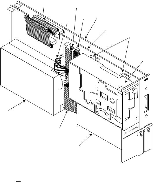
The application for the ASAI-Ethernet interface is supported by a system assembly, a ‘‘sandwich’’ of the two boards mentioned previously, the TN2208 (Multi-Function Board) and the TN2170 (Alarm Board). Figure 1-1 shows the DEFINITY LAN Gateway system assembly.
1-2 Issue 1 January 1996
Introduction
Disk drive
I2C |
SCSI |
|
|
bus cable |
bus cable |
|
|
|
|
Tie |
Multi-Function board |
|
|
(TN2208) |
|
|
Power |
wrap |
|
|
|
||
|
cable |
|
|
|
|
|
Alarm board |
|
|
|
(TN2170) |
Retaining pins
Tape drive (without cover)
AT&T
 ENTER/YES
 BACK NEXT /NO
SCSI bus cable
Power supply
Figure 1-1. DEFINITY LAN Gateway System Assembly

 NOTE:
NOTE:
The system assembly is also used to support DEFINITY AUDIX®. However, the components are populated differently for DEFINITY LAN Gateway and for DEFINITY AUDIX, so the hardware is not interchangeable. Be careful not to confuse a DEFINITY LAN Gateway system assembly with a DEFINITY AUDIX system assembly when installing or upgrading system software for either product.
Issue 1 January 1996 1-3
Introduction
The DEFINITY LAN Gateway system assembly can be distinguished from the DEFINITY AUDIX system assembly by the ‘‘TN’’ codes on the circuit packs and by a DEFINITY LAN Gateway label. The DEFINITY AUDIX system assembly uses TN566 (not shipped on new systems), TN566B, TN567, and TN2169 or TN2170. The DEFINITY LAN Gateway system assembly uses TN2170 and TN2208.
The TN2170 circuit pack supports a hard disk, Ethernet controller, and removable media. It also supports a serial port, an additional analog modem port, and remote maintenance hardware.
The TN2208 circuit pack supports a 32Mhz 486SLC Central Processing Unit (CPU) with 16MB of fixed (non-socketed) memory. It has 2 serial ports and a user interface/Liquid Crystal Display (LCD) panel. Naturally, it also has an interface to DEFINITY call control and switching fabric.
System Software
The software that provides the DEFINITY LAN Gateway application on the system assembly comes preloaded on the system when it is shipped from the factory. It is also supplied on removable media that can be reinstalled or used to upgrade an existing system.
The function of the software is to act as a mapper (or brouter) for ASAI messages. It links an ISDN network (DEFINITY call control) to a TCP/IP network (computer client) by moving ASAI messages back and forth from Q.921 synchronous data frames to TCP/IP Ethernet packets. It also associates computer clients (by their TCP/IP network addresses) to physical ports on DEFINITY that are administered as ASAI extensions.
This mapping provides a virtual point-to-point connection between a particular computer client and an associated port on DEFINITY. This arrangement continues to support the ASAI ability to sense when a particular computer client connection is lost and send an alarm. It also provides a more secure environment by fixing the addresses of the clients that may receive
DEFINITY LAN Gateway service.
1-4 Issue 1 January 1996

Introduction
Upgrading Your Existing System
If you want to have CallVisor ASAI over the DEFINITY LAN Gateway in a non-supported switch, you must upgrade it with a field maintenance release of G3V4 software. Contact the Technical Service Center at 1 800 248-1234 for more information. (You will be prompted for your Social Security Number and 4-digit PIN.)
If you attempt to upgrade from a pre-G3V4 switch, you must remove the translations (assuming you had the TN2208 circuit pack aliased as a BRI circuit pack in the pre-G3V4 switch).
!WARNING:
If you upgrade your system yourself, follow these precautions:
To prevent damage to the DEFINITY LAN Gateway system assembly, make sure that you have connected the system assembly adapter cables to the port connectors on the back of the switch (see Step 2 in Task 5: Install the DEFINITY LAN Gateway System Assembly in Chapter 2) before you insert the system assembly in the switch carrier.
You can install the system assembly in the switch when the switch is powered on or off. When the assembly is inserted in the slots of the switch carrier, it will automatically power up, run diagnostics, and boot. To avoid a disk crash, never remove the assembly without first completing the shutdown procedure to shut down the DEFINITY LAN Gateway system (and allowing the disk to completely spin down).
For the same reason, do not cycle the power on the switch (for example, during switch acceptance tests) once the system assembly is inserted unless you have first shut down the DEFINITY LAN Gateway system. Refer to the maintenance screens in Chapter 3 for the shutdown procedure.
Security Considerations
Toll fraud is the unauthorized use of a company’s telecommunications system by an unauthorized third party. DEFINITY LAN Gateway offers the following security features to help prevent toll fraud and protect against unauthorized users gaining access to the system and learning the content of calls:
Password protection — The system requires administrators to provide a password before access is granted. Also, when the system is installed, default passwords are changed to help guard against unauthorized access.
Audit trail — DEFINITY LAN Gateway provides selective logging of an audit trail of operations carried across the interface. Users can view a set of Security Logs to learn such information as failed login attempts,
Issue 1 January 1996 1-5
Introduction
unauthorized client access attempts, time of Multi-Function Board resets, and commands executed from Administration/Maintenance screens.
This system does not support an encrypted/secured protocol; therefore, it is possible for a criminal hacker to ‘‘spoof’’ the system by reverse engineering the protocol and then ‘‘impersonating’’ a valid DEFINITY LAN Gateway client.
This is more likely to occur if the hacker has physical access to the Ethernet LAN or to a system attached to the Ethernet LAN that supports the DEFINITY LAN Gateway. Customers are encouraged to help protect the system and reduce the possibility of toll fraud occurring by attaching the system assembly and its clients to an isolated, physically secure Ethernet (not connected to any other Ethernet).
1-6 Issue 1 January 1996

Installation |
2 |
|
This chapter consists of three sections:
Prerequisites
Hardware Installation
Initial Administration

 NOTE:
NOTE:
This chapter is for AT&T services personnel. Normally, AT&T installs the DEFINITY LAN Gateway system. However, the customer is responsible for DEFINITY switch administration during installation. Customers may want to read this chapter to understand what AT&T services personnel will be doing during installation to facilitate a productive visit.
If the system is already installed, proceed to Chapter 3, ‘‘System
Administration.’’
Prerequisites
This section provides prerequisites for installing a DEFINITY LAN Gateway system. These include:
Task 1: Verify the selected site
Task 2: Gather required tools
Task 3: Review safety considerations
Task 4: Verify components and connectivity.
Before beginning the installation, make sure you have completed these prerequisites. Each is detailed in the remainder of this section.
Issue 1 January 1996 2-1
Installation
Task 1: Verify the Selected Site

 NOTE:
NOTE:
Defining the system requirements and ensuring that the site meets these requirements are the responsibility of the Project Manager and the customer and must be completed before you install the DEFINITY LAN Gateway system. However, the guidelines are listed here so that you are aware of these requirements.
Verify that the site selected for the DEFINITY switch and the DEFINITY LAN Gateway system provides the following:
A DEFINITY Generic 3V4 switch, or DEFINITY Generic 3V4 software that incorporates a field maintenance upgrade for G3V2/V3.
For a DEFINITY LAN Gateway system being installed in an existing switch, five contiguous slots in a switch carrier to house the DEFINITY LAN Gateway system (slots 16 to 20 in Figure 2-1 that follows). (See Appendix A for carrier worksheets.)
AT&T AT&T AT&T AT&T |
AT&T AT&T AT&T |
AT&T AT&T AT&T AT&T AT&T AT&T |
. |
. |
. |
. |
. |
. |
. |
. |
. |
. |
. |
. |
. |
. |
6 . |
. |
. |
. |
. |
. |
. |
. |
. |
. |
. |
. |
. |
. |
. |
. |
. |
. |
. |
. |
. |
. |
. |
. |
. |
. |
. |
. |
3 . |
. |
. |
. |
. |
. |
. |
. |
. |
. |
. |
. |
. |
. |
1 . |
. |
. |
. |
. |
. |
. |
. |
. |
. |
. |
. |
. |
. |
. |
. |
. |
. |
. |
. |
. |
. |
. |
. |
. |
. |
. |
. |
D . |
. |
. |
. |
. |
. |
. |
. |
. |
. |
. |
. |
. |
. |
A . |
. |
. |
. |
. |
. |
. |
. |
. |
. |
. |
. |
. |
. |
T |
A |
M |
Z |
|
|
|
A |
L |
F |
1 |
|
|
|
P |
B |
B |
0 |
|
|
|
E |
|
|
|
|||
|
|
|
0 |
|
|
|
|
|
|
C |
|
|
|
|
|
|
A |
|
|
|
|
|
|
P |
|
|
|
D |
T |
T |
P. |
. |
||
I |
N |
N |
B |
6 . |
||
S |
2 |
2 |
|
. |
||
K |
L |
|
|
3 . |
||
|
1 |
2 |
A |
|
|
1 .. |
|
7 |
0 |
|
|
||
|
N |
|
|
D . |
||
|
0 |
8 |
K |
|
|
B . |
|
|
|
||||
|
|
|
|
|
|
|
|
B |
|
POWER |
TONE- |
EXPN |
|
|
|
|
|
|
|
|
|
|
|
|
|
|
|
|
|
|
|
|
|
|
|
|
|
|
|
|
|
|
|
|
|
|
|
|
|
|
|
|
|
|
|
|
|
|
|
|
|
|
|
|
|
POWER UNIT |
|||||
|
POWER UNIT |
UNIT |
CLOCK |
INTFC |
|
|
|
|
|
|
|
|
|
|
|
|
|
|
|
|
|
|
|
|
|
|
|
|
|
|
|
|
|
|
|
|
|
|
|
|
|
|
|
|
|
|
|
|
|
|
|
|
|
|
|
|
|
|||||||
|
|
|
SERVICE |
1 |
|
2 |
|
3 |
|
4 |
|
5 |
|
6 |
|
7 |
|
8 |
|
9 |
|
10 |
11 |
|
|
12 |
13 |
14 |
15 |
16 |
17 |
18 |
19 |
20 |
||||||||||||||||||||||||||||||
|
|
|
|
|
|
|
|
|
|
|
|
|
|
|
|
|
|
|
|
|
|
|
|
|
|
|
|
|
|
|
|
|
|
|
|
|
|
|
|
|
|
|
|
|
|
|
|
|
|
|
|
|
|
|
|
|
|
|
|
|
|
|
|
|
|
|
|
|
TOP WHITE |
|
|
|
|
|
|
|
|
|
|
|
|
|
|
|
|
|
|
|
|
|
|
|
|
|
PURPLE SLOTS |
|
|
|
|
|
|
|
|
|
|
|
|
|
|
|
|
|
|
|
|
|
|
|
|
|
|
||||||||
|
|
|
BOTTOM PURPLE |
|
|
|
|
|
|
|
|
|
|
|
|
|
|
|
|
|
|
|
|
|
|
|
|
|
(PORT SLOTS) |
|
|
|
|
|
|
|
|
|
|
|
|
|
|
|
|
|
|
|
|
|
|
|
|
|
|
|||||||||
|
|
|
|
|
|
|
|
|
|
|
|
|
|
|
|
|
|
|
|
|
|
|
|
|
|
|
|
|
|
|
|
|
|
|
|
|
|
|
|
|
|
|
|
|
|
|
|
|
|
|
|
|
|
|||||||||||
|
|
|
|
TWO SLOTS |
|
|
|
|
|
|
|
|
|
|
|
|
|
|
|
|
|
|
|
|
|
|
|
|
|
|
|
|
|
|
|
|
|
|
|
|
|
|
|
|
|
|
|
|
|
|
|
|
|
|
|
|||||||||
|
|
|
|
|
|
|
|
|
|
|
|
|
|
|
|
|
|
|
|
|
|
|
|
|
|
|
|
|
|
|
|
|
|
|
|
|
|
|
|
|
|
|
|
|
|
|
|
|
|
|
|
|
|
|
|
|
|
|
|
|
||||
Figure 2-1. DEFINITY LAN Gateway System in a Switch Carrier
A LAN connection available to the system prior to hookup. This connection to the LAN is provided by the customer for AT&T at an agreed-upon demarcation point.
Easy access for cabling
Good workspace for the system administrator and/or operators
Temperature range of 50 to 100 F (10 to 38 C), with the ideal range between 50 and 80 F
2-2 Issue 1 January 1996

Installation
Humidity range of 20% to 80%, noncondensing. In addition, make sure the site is secure and provides protection from excessive sunlight, heat, cold, chemicals, static electricity, magnetic fields, vibration, and grime.

 NOTE:
NOTE:
ASAI must be enabled on the DEFINITY Customer Options form for the system to be fully operational.
Task 2: Gather Required Tools
To install a DEFINITY LAN Gateway system, you need the following tools:
Narrow width, flat-blade screwdriver
1/4-inch nut driver (recommended)
Antistatic grounded wrist strap
Punch-down tool
Task 3: Review Safety Considerations
!WARNING:
Electronic equipment can be damaged by electrostatic discharge. Do not touch any electronic component unless you are properly grounded.
!DANGER:
Do not touch the switch backplane while installing the DEFINITY LAN Gateway system. The backplane contains dangerous voltages and current.
To prevent damage to the equipment and yourself, adhere to the following:
Make sure you are familiar with the procedures necessary to prevent electrostatic damage to the equipment.
Properly ground a wrist strap.
Place the grounded wrist strap on your bare wrist. (The wrist strap must contact your bare skin directly — do not wear it over your clothes.)
Do not remove the system assembly from the polyethylene bag until:
—Your wrist strap is on your wrist and properly grounded.
—You have made room in the switch carrier and you are ready to insert the system assembly in the carrier.
If you need to work on the system assembly — that is, disassemble it — place the assembly on a grounded antistatic work mat.
Issue 1 January 1996 2-3

Installation
Task 4: Verify Components and
Connectivity
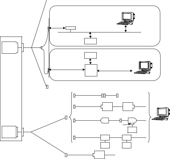
Study Figure 2-2 that follows to gain a general understanding of how the system assembly is to be connected. Some customer-furnished LAN equipment is included within the dotted lines in this figure. Helpful definitions for this equipment are as follows.
Balun (balanced/unbalanced) — An impedance matching transformer. Baluns are small, passive devices that convert the impedance of coaxial cable so that its signal can run on twisted-pair wiring. They are used often so that IBM 3270-type terminals, which traditionally require coaxial cable connection to their host computer, can run off twisted-pair. Baluns work for some types of protocols and not for others. There is often some performance degradation with baluns, and the signal cannot run as far on twisted wire as it can on coaxial cable.
10BaseT Hub — An Ethernet LAN that works on twisted pair wiring which looks and feels like telephone cabling. 10BaseT Ethernet LANs work on home runs in which the wire from each workstation snakes directly to the 10BaseT hub (like the wiring of a phone system). The advantages are twofold — first, if one machine crashes, it doesn’t bring down the whole network, and second, 10BaseT hubs often come with sophisicated management software.
2-4 Issue 1 January 1996
Installation
Switch
Alarm
Board
Multi-
Function
Board
ALB
Cable
MFB
Y
Cable
 (Not Used)
Telnet Management
Client
|
10BaseT |
|
|
|
|
|
(Twisted |
|
|
|
|
|
Pair) |
|
|
|
|
Balun |
|
|
|
|
|
|
Ethernet Coaxial Cable |
|
|
||
|
|
LAN |
DEFINITY LAN Gateway Client |
||
RJ45 |
|
Server |
|
|
|
|
|
|
|
|
|
|
|
LAN |
DEFINITY LAN Gateway Client |
||
|
|
Server |
|
|
Telnet Management |
|
|
|
|
|
Client |
|
10BaseT |
|
|
|
|
|
(Twisted Pair) |
10BaseT |
|
|
|
|
HUB |
|
|
|
|
|
|
|
|
|
|
|
TN2170 RS-232 |
|
|
|
|
|
|
|
Null Modem |
|
|
|
H600-258 G1 |
|
|
|
|
|
|
|
|
|
|
|
|
|
|
T/R |
Modem |
|
|
|
Modem |
||
|
Admin/Port B |
|
|
House |
|
|
|
|
|
|
|
|
|
|
Z3A4 Wiring |
Z3A1 |
|
|
|
|
|
Adapter |
Terminal |
|
|
|
|
|
|
|
|
|
|
Site- |
Power |
|
|
|
|
Supply |
|
|
|
|
|
Specific |
|
|
|
|
|
|
|
|
|
|
|
Connection |
7400B |
|
|
|
7400A |
||
|
|
|
Power |
|
Power |
|
|
|
Supply |
Supply |
|
|
Main/Port A |
|
|
|
|
|
G311 |
|
Modem |
T/R |
|
|
ED 1E434-11 |
|
|
|
|
|
|
|
|
|
|
|
|
AT&T Services Remote Access |
|||
NOTES: |
Software |
|
Demarcation Point |
||
— Installed by customer |
||
— Provided by AT&T |
||
— Maintained by customer |
||
— RJ45 connection |
||
The TN2170 can have similar |
||
using a D8W modular wall cord |
||
connections as on Admin/Port B. |
||
— Located on cross-connect field |
||
|
||
— Maximum distance - 25 feet from switch |
9600 baud modem |
|
|
|
Figure 2-2. DEFINITY LAN Gateway External Connections
Issue 1 January 1996 2-5

Installation
Refer to the diagrams in Tasks 6 and 7 in section 2 of this chapter, Hardware Installation, for additional connectivity details. Then compare the parts listed in Appendix C, ‘‘Ordering Information’’ with the actual parts you received to make sure that all required parts have been ordered and shipped correctly.

 NOTE:
NOTE:
The components listed in Appendix C are not the only equipment that can be used with the DEFINITY LAN Gateway system. Other terminals, PCs, and modems are also supported.
2-6 Issue 1 January 1996

Installation
Hardware Installation
This section describes the tasks needed to install the DEFINITY LAN Gateway system hardware and peripheral hardware.
The DEFINITY LAN Gateway system installation tasks are the same for all switch types. These tasks include:
Task 5: Install the DEFINITY LAN Gateway system assembly
Task 6: Connect the Alarm Board cables
Task 7: Install the terminal (optional)
Task 8: Connect the Maintenance Modem
Task 9: Finalize and test the hardware
Before beginning these tasks, refer to the following worksheets:
Appendix A, PBX Carrier Configuration Worksheets
A-1, Port Slot Assignments (Before Carrier Rearrangement)
A-2, Port Slot Assignments (For Carrier Rearrangement)
A-3, Port Slot Locations for the DEFINITY LAN Gateway System
Assembly
Appendix B, Supported Terminals and Modems/Option Settings
B-1, Terminals/Modems
Task 5: Install the DEFINITY LAN Gateway
System Assembly
This task is required for all installation scenarios.
!WARNING:
To prevent damage to the DEFINITY LAN Gateway system assembly, make sure that you (or the factory, for new switches) have connected the system assembly adapter cables to the port connectors on the back of the switch (as described in Step 3) before you insert the system assembly in the switch carrier.
You can install the system assembly in the switch when the switch is powered on or off. When the assembly is inserted in the slots of the switch carrier, it will automatically power up, run diagnostics, and boot. To avoid a disk crash, never remove the assembly without first completing the shutdown procedure to shut down the DEFINITY LAN Gateway system (and allowing the disk to completely spin down).
Issue 1 January 1996 2-7

Installation
For the same reason, do not cycle the power on the switch (for example, during switch acceptance tests) once the system assembly is inserted unless you have first shut down the DEFINITY LAN Gateway system. Refer to the maintenance screens in Chapter 3 for the shutdown procedure.
Slot and Carrier Restrictions
If rearrangement of circuit packs in the PBX is required to accommodate the system assembly, rearrange the packs as indicated on Worksheet A-2, Port Slot Assignments, before proceeding.
There is a maximum of one system assembly per Single Carrier Cabinet (SCC) or MultiCarrier Cabinet (MCC). This assembly occupies five slots and should be placed to the far right in the carrier. For thermal reasons, the system assembly should not be placed in MultiCarrier Cabinet C carrier position (top carrier position).
See Appendix A, ‘‘PBX Carrier Configuration Worksheets,’’ for detailed information on the rearrangement of circuit packs and slot restrictions.
DEFINITY LAN Gateway System Slots
The system assembly requires five contiguous port slots in the switch carrier. In this description, the five slots are referred to as the first through the fifth slot, with the understanding that they can be any five contiguous port slots. It is recommended that it be installed as far to the right as possible.
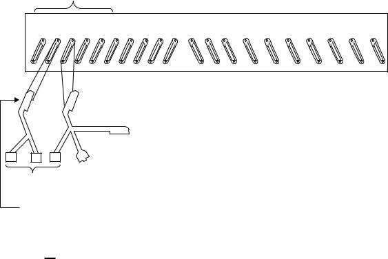
The slots are numbered from left to right on the front panel of the switch cabinet, and from right to left on the rear panel as shown in Figure 2-3, Connecting the Adapter Cables, Rear-Panel View. The five port slots are occupied by the DEFINITY LAN Gateway system assembly as follows:
The first and second slots are covered by the DEFINITY LAN Gateway disk and removable media and are not connected to the switch backplane or amphenol connectors.
The third slot is connected to the Alarm Board (ALB).
The fourth slot is connected to the Multi-Function Board.
The fifth slot remains vacant to provide added clearance and cooling for certain components on the Multi-Function Board.
2-8 Issue 1 January 1996
Installation
Example of
DEFINITY LAN Gateway Slots
5th 4th 3rd 2nd 1st
20 |
19 |
18 |
17 |
16 |
15 |
14 |
13 |
12 |
11 |
10 |
9 |
8 |
7 |
6 |
5 |
4 |
3 |
2 |
1 |
ALB Cable
(H600-353-G2)
Amphenol Connector (not used)
Female RJ45
Female
RS-232
MFB Y-Cable
(H600-352-G1)
Figure 2-3. Connecting the Adapter Cables Rear-Panel View

 NOTE:
NOTE:
If the DEFINITY LAN Gateway system was shipped in a new switch, skip to Step 7 of this task.
Installation Steps
Using Worksheet A-3, Port Slot Locations for the DEFINITY LAN Gateway System Assembly, follow the steps below to install the system assembly.
1.Remove any existing cables from the third and fourth slots of the five contiguous slots reserved for the DEFINITY LAN Gateway system. For example, if you are to install the DEFINITY LAN Gateway system in slots 7 through 11 of carrier A in the switch, remove the I/O cables from slots 8 and 9. (These are the two slots that provide connectivity to the DEFINITY LAN Gateway system circuit packs.)
2.Referring back to Figure 2-3 and to Steps 2a and 2b that follow, connect the DEFINITY LAN Gateway system assembly adapter cables to the port connectors on the back of the switch.
Issue 1 January 1996 2-9

Installation

 NOTE:
NOTE:
You must connect these adapter cables directly to the port connectors on the switch. If you install another cable between the switch and the cables, the DEFINITY LAN Gateway system will not operate correctly (either now or in the future).
a.Attach the male D-type amphenol connector on the Alarm Board (ALB) cable (the one with two amphenol connectors, one RJ45 LAN connector, and one 25-pin RS-232 connector) to the ALB (TN2170), the third slot of the five DEFINITY LAN Gateway system slots.
b.Attach the male D-type amphenol connector on the Multi-Function Board (MFB) Y-cable (the one with one amphenol and two RS-232 connectors) to the MFB (TN2208), the fourth slot of the five DEFINITY LAN Gateway system slots.

 NOTE:
NOTE:
If you are installing the DEFINITY LAN Gateway system in a DC-powered switch, perform the following steps to install the 116A isolating data interface. Otherwise, skip to Step 4.
3.Install the 116A isolating data interface.
a.Attach the male end of a null modem (supplied with the DEFINITY LAN Gateway system PEC) to the RS-232C connector on both PORT A and PORT B on the MFB Y-cable. Attach the male connector of the 116A to the other end of the null modem.
b.Attach the male end of another null modem to the RS-232 connector labeled RESERVED on the ALB Y-cable. Attach the male connector of the second 116A to the other end of the null modem.
4.Insert the system assembly (see Figure 2-4, DEFINITY LAN Gateway System Assembly) into the switch cabinet as follows:
Holding the system assembly by the outside edges of the faceplate, line up the Alarm Board and the Multi-Function Board with the bottom guides of the third and fourth slots, respectively, of the five reserved port slots in the switch carrier.
2-10 Issue 1 January 1996

Installation
Disk drive
I2C |
SCSI |
|
|
bus cable |
bus cable |
|
|
|
|
Tie |
Multi-Function board |
|
|
(TN2208) |
|
|
Power |
wrap |
|
|
|
||
|
cable |
|
|
|
|
|
Alarm board |
|
|
|
(TN2170) |
Retaining pins
Tape drive (without cover)
AT&T
 ENTER/YES
 BACK NEXT /NO
SCSI bus cable
Power supply
Figure 2-4. DEFINITY LAN Gateway System Assembly
!WARNING:
The DEFINITY LAN Gateway system will automatically boot when seated in the slots. Damage to the disk could occur if the assembly is removed while booting. Therefore, try to avoid the need to adjust or reinsert the assembly after the first attempt to insert it; make sure that the assembly is properly aligned in the slot, and then insert it with a single firm push.
Issue 1 January 1996 2-11
Loading...