


service overview
1Chapter
Service Overview
Carefully read through this chapter for a look at various components of the notebook and necessary cautions and tools before performing any service and repairs.
To provide the best service and support for the ASUS S96J Series, we have provided the below information for technicians from distributors and resellers to perform the complete notebook disassembly and assembly. But before performing the procedures, please be sure to read through the overview in this chapter for component overview,
cautions and tools to avoid any unwarranted damages to the notebook’s hardware.
The following chapter includes:
•S96J Overview
•Components
•Precautions
•Appropriate Tools
1-1
service overview
S96J Series Overview and Components
The ASUS S96 Series Notebook is a product combining the power of Intel® Pentium M CPU with uFC-PGA mobile system. In this section, an overview for the S96J, along with its components, will be presented.
O V E R V I E W
S96J Overview
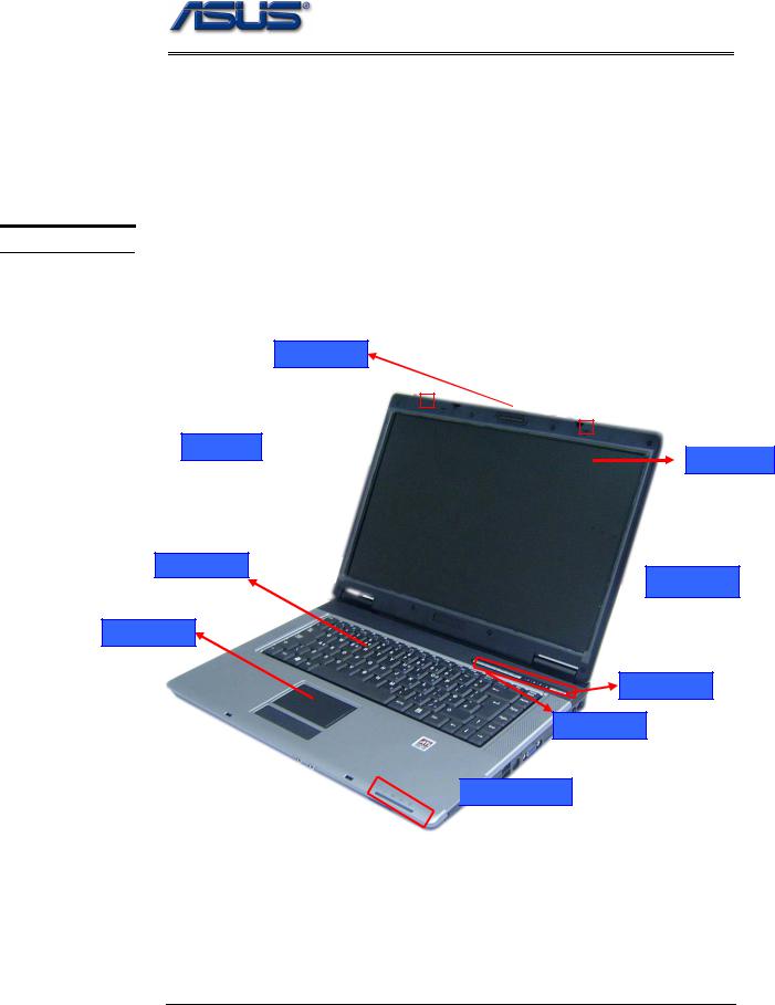
The illustrations below show the notebook’s overview from front view, right side view, left side view, and rear side view. Most of the parts will be discussed in this manual.
LCD Latch
MIC 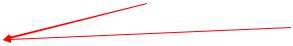
 LCD panel
Keyboard
 LCD Bezel
Touch Pad
Power switch
Instant Key
 LED Indicators
1 – 2
service overview
Audio jacks |
|
4 in 1 card reader |
|
|
|
Kensington |
Optical Drive Reader |
lock port |
IEEE 1394 |
|
TV-OUT Port |
|
Modem Port |
|
|
|
|
|
|
|
|
|
|
|
LAN Port |
PCI Express |
|
USB(2.0) |
|
VGA Port |
|
|
|
|
|
|
|
|
|
DC power input |
|
Air vents |
|
USB (2.0) |
|
|
|
|
|
Battery Module |
|||
|
|
|
|
|
|
|
|
|
|
|
|
|
|
1 - 3
C O M P O N E N T S
L C D
L C D
B R A C K E T S
I N V E R T E R
B O A R D
M O D U L E
L C D H I N G E
service overview
Components
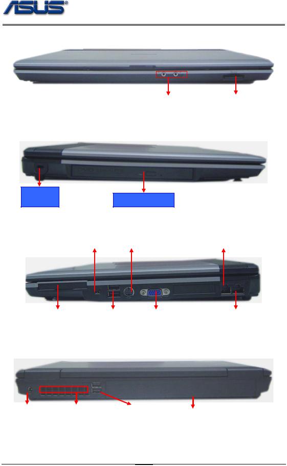
The illustrations below show the components of the S96J Series.
LCD Panel*
The illustration below shows the LCD display panel. The S96J Series notebook comes with 15.4” TFT LCD Panel.
LCD Bracket
The illustration below shows the LCD Bracket.
Inverter Board
The illustration below shows the inverter board, which is hidden underneath the lower edge of the LCD front bezel.
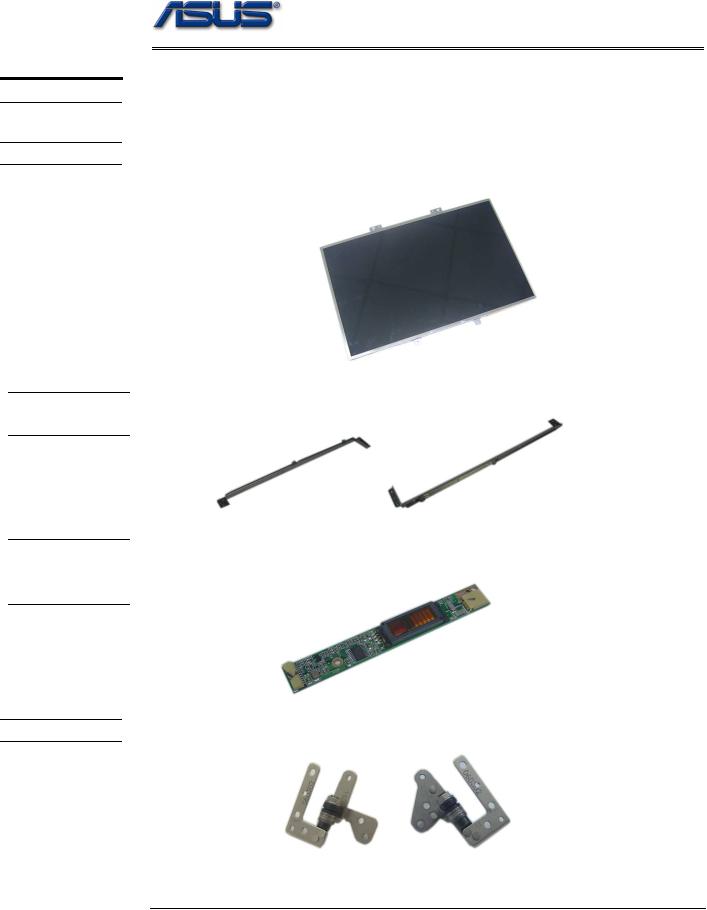
LCD Hinge
The illustration below shows the LCD Hinges.
1 - 4
L C D C A S E
K E Y B O A R D
T O P C A S E &
T O U C H P A D
service overview
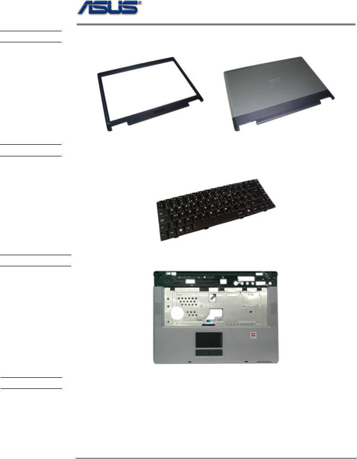
LCD Case
The illustration below shows the LCD case. Here is the LCD front cover, back cover.
Keyboard
The illustration below shows the keyboard plate. It can be exchanged with keyboard plates with different language layouts, such as U.S., German, Japanese, British, France and others.
Top Case Module
The illustration below shows the top case of the notebook..
Touch Pad Module
The illustration below shows the Touch Pad module.
1 - 5
B A T T E R Y
O P T I C A L
D R I V E
H D D B R A C K E T
service overview
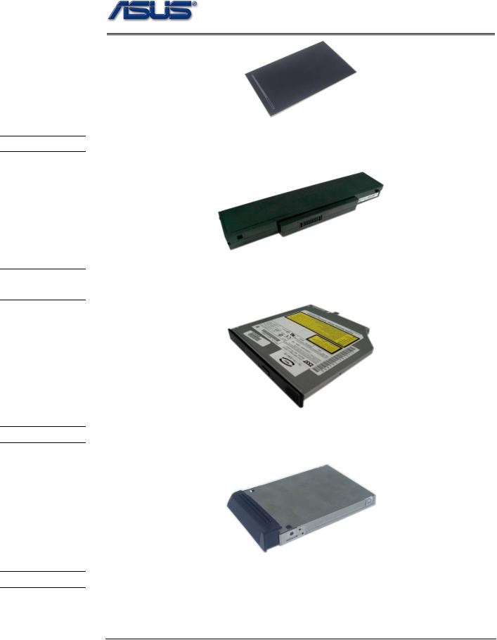
Battery Pack
The illustration below shows the battery pack of the notebook. It’s located at bottom of the notebook.
Optical Drive
The illustration below shows the Optical Drive
HDD Bracket
The illustration below shows the HDD Bracket.
H D D D R I V E
Hard Disk Drive
The illustration below shows the 2.5” industry-standard HDD with 9.5mm height.
1 - 6

C P U
C P U T H E R M A L
M O D U L E
C P U D O O R
service overview
uFC-PGA CPU Module
The illustration below shows the Intel uFC-PGA CPU Module, top and bottom views
CPU Thermal Module
The illustration below shows the thermal module for the CPU. It’s located on the top of CPU.
CPU door
The illustration below shows CPU door.
1 - 7
M E M O R Y
M O T H E R
B O A R D
M O D U L E
B O T T O M C A S E
K / B C O V E R
M O D U L E
service overview
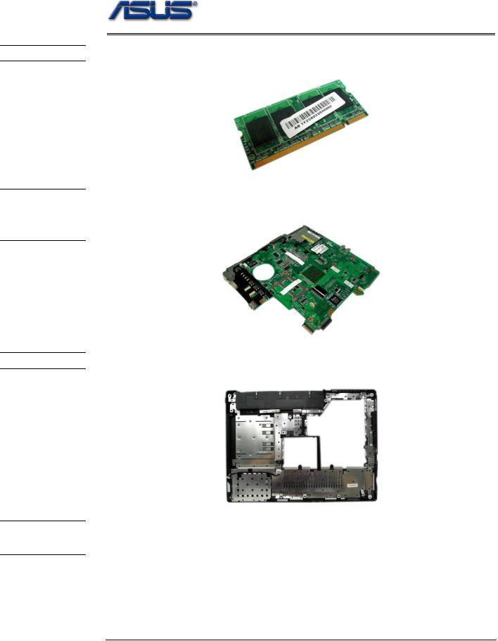
Memory Module
The illustration below shows the industry-standard 200pin SO-DIMM DDR SDRAM module for the notebook.
Motherboard Module
The illustration below shows the motherboard module of the notebook.
Bottom Case Module
The illustration below shows the bottom case module of the notebook. It include speaker sets
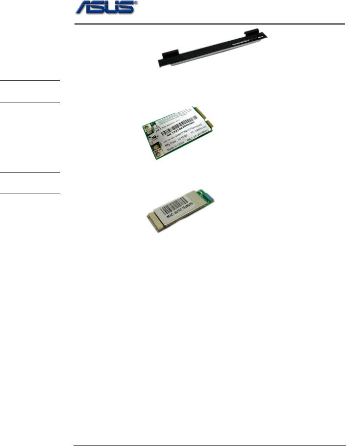
K/B Cover Module
The illustration below shows the keyboard cover.
1 - 8
W I R E L E S S L A N M O D U L E
B L U E T O O T H
M O D U L E
service overview
Wireless LAN Module
The illustration below shows the Wireless LAN Module of the notebook. It contains Wireless LAN Card.
Bluetooth Module
The illustration below shows the Bluetooth Module of the notebook.
1 - 9
C A U T I O N S
service overview
Service Overview
Please pay special attention to the cautions below to prevent any damages to the notebook and also please be sure to select the appropriate tools described in this section to perform any services desired.
Precautions
Before you perform any service and/or repair on the notebook, please follow the steps below first.
1.Be sure that the notebook is powered down.
2.Disconnect the AC plug from the notebook
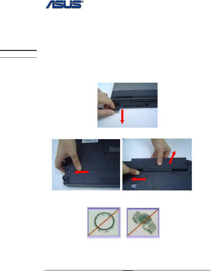
3. Turn the notebook over. Unlock and hold the latches, and remove the battery.
3.Remove all rings, watches and any other metal objects from your hands.
4.Always wear a ground strap on your hand to protect the notebook from static discharge.
1 - 10
T O O L S
C R O S S
S C R E W -
D R I V E R
F L A T H E A D
S C R E W -
D R I V E R
T W E E Z E R S
I N S E R T I O N
A N D
E X T R A C T I O N T O O L F O R
F P C
C O N N E C T O R
V A C U U M H A N D L I N G T O O L
service overview
Appropriate Tools
The illustrations below show the appropriate tools that should be used for the notebook’s service and repair.
Phillips-head Screwdriver
Use a Phillips-head screwdriver to fasten/remove the K- or B-typed screws.
Single-Slotted Screwdriver
Use a single-slotted screwdriver to lock/unlock the flexible cable connector locks
Tweezers
Use a pair of tweezers to remove/insert flexible cables.
Insertion and extraction tool for FPC connector
Use insertion and extraction tool for FPC connector to handle locking and unlocking of FPC connectors.
Vacuum Handling Tool
1 - 11

Disassembly procedure
2Chapter
Disassembly Procedure
Please follow the information provided in this section to perform the complete disassembly procedure of the notebook. Be sure to use proper tools described before.
ASUS S96J Series Notebook consists of various modules. This chapter describes the procedures for the complete notebook disassembly. In addition, in between procedures, the detailed disassembly procedure of individual modules will be provided for your service needs.
The disassembly procedure consists of the following steps:
•Battery Module
•HDD Module
•Memory Module
•WLAN Module
•CPU Module
•Optical Drive Module
•Keyboard Module
•Top Case Module
•Motherboard Module
•Bottom case Module
•LCD Module
2 - 1
B A T T E R Y
H D D
M O D U L E
H D D
M O D U L E R E M O V A L
Disassembly procedure
Battery Module
The illustration below shows how to remove the battery module.
1. Turn the notebook over. Unlock and hold the latch, and remove the battery.
3
2 |
1 |
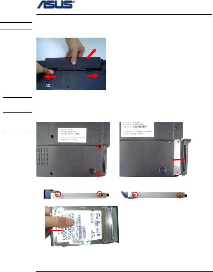
HDD Module
The illustrations below show how to remove the HDD module from the notebook.
Removing HDD Module
1. Remove 2 screws and take the HDD out.
2. Remove 4 screws to separate HDD from HDD housing
2 - 2
M E M O R Y M O D U L E
M E M O R Y R E M O V A L
Disassembly procedure
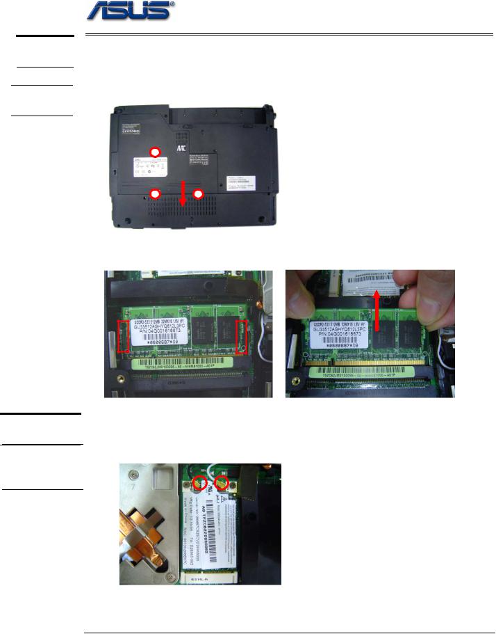
Memory Module
The illustration shows how to remove the memory module form the notebook.
Removing Memory module
1. Remove 3 screws and take the CPU door away.
2. Pull two Latches and pop the module up to a 45° angles, and then pulling out the module in that angle.
W L A N
M O D U L E
W L A N
M O D U L E R E M O V A L
WLAN Module
The illustrations below show how to remove the WLAN module from the notebook.
Remove WLAN module
1. Remove 2 Antenna cables from Wireless LAN Module
2 - 3
C P U M O D U L E
R E M O V A L
C P U
R E M O V A L
Disassembly procedure
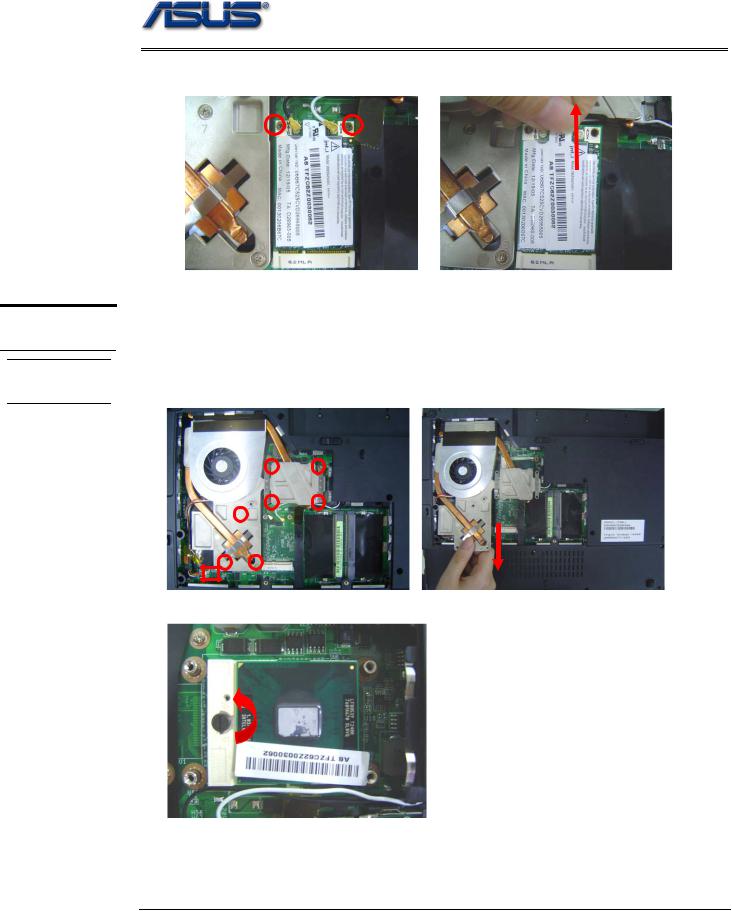
2. Remove 2 screws then take the WLAN module away.
CPU Module
The illustrations below show how to remove the CPU module from the notebook.
Removing CPU
1.Disconnect the FAN cable and remove 7 screws from 1 to 7, then take away the thermal module
3 2
1 4
7
5
6
2. Turn the non-removable screw here 180 degrees counter-clockwise to loosen the CPU.
2 - 4
Disassembly procedure
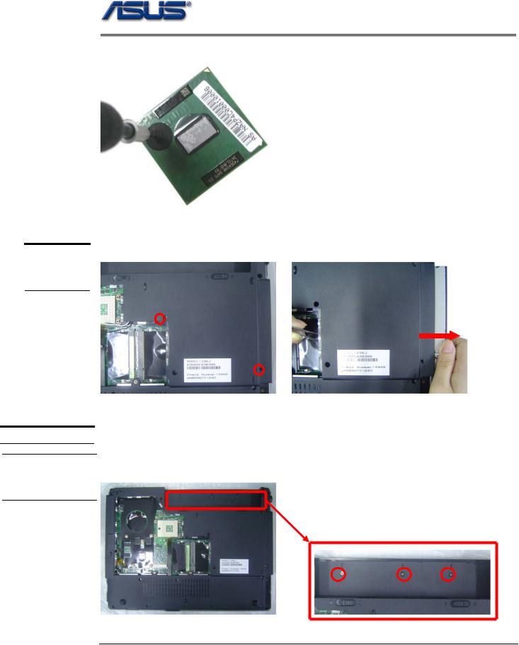
3. Squeeze the vacuum handling pump and use it to lift the CPU away.
O P T I C A L
D R I V E
R E M O V A L
K E Y B O A R D
I N D I C A T O R
C O V E R
R E M O V A L
Optical Drive Module
1. Move 2 screws here, and then pull the ODD module out slowly.
Keyboard Module
The illustration of below shows how to remove the keyboard
Removing Keyboard and indicator Cover
1. Remove 3 screws here, and then turn over the notebook.
2 - 5

Disassembly procedure
2. Unlock 9 indicator cover latches.
3. Take away indicator cover by hand
4.Pull out the keyboard forward and lay the keyboard on the front side then disconnect the FPC, then take away keyboard.
2 - 6
T O P C A S E M O D U L E
T O P C A S E M O D U L E
Disassembly procedure
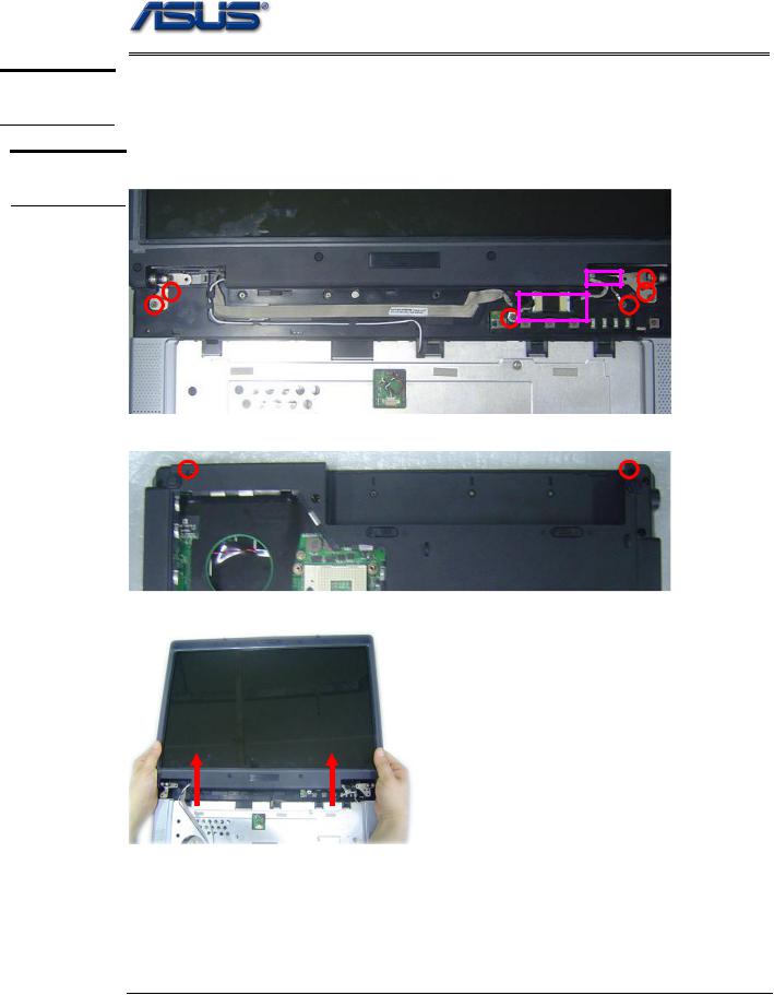
Top Case Module
The illustrations below show how to disassemble and remove the top case module of the notebook. The module contains the top case itself.
Removing top Case Module
1. Remove 6 screws here, and then disconnect the Coaxial & inverter cable.
2. Turn over the notebook, and then remove 2 screws here.
3. Separate the LCD module from the Top Case module
2 - 7
 Loading...