


RS162-E4/RX4
1U Rackmount Barebone Server
User Guide

E2667
First Edition V1.01
September 2006
Copyright 2006© ASUSTeK COMPUTER INC. All Rights Reserved.
No part of this manual, including the products and software described in it, may be reproduced, transmitted, transcribed, stored in a retrieval system, or translated into any language in any form or by any means, except documentation kept by the purchaser for backup purposes, without the express written permission of ASUSTeK COMPUTER INC. ("ASUS").
ASUS provides this manual "as is" without warranty of any kind, either express or implied, including but not limited to the implied warranties or conditions of merchantability or fitness for a particular purpose. In no event shall ASUS, its directors, officers, employees, or agents be liable for any indirect, special, incidental, or consequential damages (including damages for loss of profits, loss of business, loss of use or data, interruption of business and the like), even if ASUS has been advised of the possibility of such damages arising from any defect or error in this manual or product.
Specifications and information contained in this manual ae furnished for informational use only, and are subject to change at any time without notice, and should not be construed as a commitment by ASUS. ASUS assumes no responsibility or liability for any errors or inaccuracies that may appear in this manual, including the products and software described in it.
Product warranty or service will not be extended if: (1) the product is repaired, modified or altered, unless such repair, modification of alteration is authorized in writing by ASUS; or (2) the serial number of the product is defaced or missing.
Products and corporate names appearing in this manual may or may not be registered trademarks or copyrights of their respective companies, and are used only for identification or explanation and to the owners benefit, without intent to infringe.
Contents
Contents................................................................................................ |
i |
|
|
Federal Communications Commission Statement..................... |
v |
|
Canadian Department of Communications Statement.............. |
v |
|
Electrical Safety....................................................................... |
vi |
|
Operation Safety...................................................................... |
vi |
About this guide.................................................................................. |
vii |
|
1.Chapter 1: Product Introduction |
|
|
1.1 |
System package contents.......................................................... |
1-2 |
1.2 |
System specifications................................................................. |
1-3 |
1.3 |
Front panel features................................................................... |
1-5 |
1.4 |
Rear panel features.................................................................... |
1-5 |
1.5 |
Internal features......................................................................... |
1-6 |
1.6 |
LED information.......................................................................... |
1-7 |
|
1.6.1 Front panel LEDs.......................................................... |
1-7 |
|
1.6.2 HDD status LED........................................................... |
1-7 |
|
1.6.3 Rear panel LEDs........................................................... |
1-8 |
2.Chapter 2: Hardware setup |
|
|
2.1 |
Chassis cover.............................................................................. |
2-2 |
|
2.1.1 Remove the front cover.............................................. |
2-2 |
|
2.1.2 Removing the rear cover............................................. |
2-3 |
|
2.1.3 Install the rear cover.................................................... |
2-4 |
2.2 |
Install the CPU and heatsink....................................................... |
2-5 |
|
2.2.1 Installing a CPU............................................................ |
2-5 |
|
2.2.2 Install the CPU heatsink............................................... |
2-7 |
2.3 |
System memory......................................................................... |
2-8 |
|
2.3.1 Overview...................................................................... |
2-8 |
|
2.3.2 Memory configurations................................................ |
2-8 |
|
2.3.3 Installing a DIMM........................................................ |
2-10 |
|
2.3.4 Removing a DIMM....................................................... |
2-10 |
2.4 |
Hot-swap hard disk drives........................................................ |
2-11 |
2.5 |
Expansion slots......................................................................... |
2-13 |
|
2.5.1 Installing expenstion card.......................................... |
2-13 |
|
2.5.2 Reinstall the riser card............................................... |
2-14 |
|
2.5.3 Remove the expansion cards..................................... |
2-15 |
|
2.5.4 Installing the SAS expansion slot............................... |
2-15 |
ASUS RS162-E4/RX4 |
|

|
2.5.5 Install ZCR card (Optional)......................................... |
2-16 |
|
2.5.6 Configuring an expansion card................................... |
2-18 |
2.6 |
Cable connections.................................................................... |
2-20 |
|
2.6.1 Serial Port cable......................................................... |
2-21 |
2.7 |
SAS/SATA backplane cabling................................................... |
2-22 |
2.8 |
Remove components................................................................ |
2-23 |
|
2.8.1 System fans............................................................... |
2-23 |
|
2.8.2 Device fans................................................................ |
2-25 |
|
2.8.3 Device fan with dummy case..................................... |
2-25 |
|
2.8.4 Redundant PSU and Power backplabe board................ |
2-27 |
|
2.8.5 SAS/SATA2 Backpanel and Bridge Card.................... |
2-31 |
|
2.8.6 Optical drive.............................................................. |
2-34 |
|
2.8.7 Motherboard.............................................................. |
2-37 |
3.Chapter 3: Installation options |
|
|
3.1 |
Rackmount rail kit items............................................................. |
3-2 |
3.2 |
Rack rails assembly..................................................................... |
3-2 |
3.3 |
Attaching the rails to the rack................................................... |
3-3 |
3.4 |
Rackmounting the server........................................................... |
3-4 |
4.Chapter 4: Motherboard information |
|
|
4.1 |
Motherboard layout.................................................................... |
4-2 |
4.2 |
Jumpers...................................................................................... |
4-4 |
4.3 |
Connectors................................................................................. |
4-8 |
5.Chapter 5: BIOS information |
|
|
5.1 |
Managing and updating your BIOS.............................................. |
5-2 |
|
5.1.1 Creating a bootable floppy disk................................... |
5-2 |
|
5.1.2 Updating the BIOS using the Phoenix Phlash16 Utility..5-3 |
|
|
5.1.3 ASUS CrashFree BIOS 2 utility..................................... |
5-4 |
|
5.1.4 ASUS Update utility..................................................... |
5-6 |
5.2 |
BIOS setup program................................................................... |
5-9 |
|
5.2.1 BIOS menu screen...................................................... |
5-10 |
|
5.2.2 Menu bar.................................................................... |
5-10 |
|
5.2.3 Legend bar................................................................. |
5-11 |
|
5.2.4 Menu items................................................................ |
5-11 |
|
5.2.5 Sub-menu items......................................................... |
5-11 |
|
5.2.6 Configuration fields.................................................... |
5-11 |
ii
|
5.2.7 Pop-up window.......................................................... |
5-12 |
|
5.2.8 General help............................................................... |
5-12 |
5.3 |
Main menu................................................................................ |
5-13 |
|
5.3.1 System Date [Day xx/xx/xxxx]................................. |
5-13 |
|
5.3.2 System Time [xx:xx:xx]............................................. |
5-13 |
|
5.3.4 IDE Configuration....................................................... |
5-14 |
|
5.3.5 IDE Channel 0 Master/Slave SATA Port 1/2/3/4...... |
5-16 |
|
5.3.6 System Information................................................... |
5-17 |
5.4 |
Advanced menu........................................................................ |
5-19 |
|
5.4.1 Advanced Processor Options..................................... |
5-19 |
|
5.4.2 Chipset Configuration................................................ |
5-21 |
|
5.4.3 PCI Configuration....................................................... |
5-23 |
|
5.4.4 ICH USB Control Sub-Menu......................................... |
5-24 |
|
5.4.5 Peripheral Devices Configuration............................... |
5-25 |
|
5.4.6 ACPI Configuration..................................................... |
5-26 |
|
5.4.7 Power On Configuration............................................. |
5-27 |
|
5.4.8 Hardware Monitor...................................................... |
5-28 |
5.5 |
Server menu............................................................................. |
5-31 |
5.6 |
Security menu.......................................................................... |
5-34 |
5.7 |
Boot menu ............................................................................... |
5-36 |
|
5.7.1 Boot Device Priority................................................... |
5-36 |
|
5.7.2 Boot Features............................................................ |
5-37 |
5.8 |
Exit menu................................................................................. |
5-38 |
6.Chapter 6: RAID configuration |
|
|
6.1 |
Setting up RAID.......................................................................... |
6-2 |
|
6.1.1 RAID definitions........................................................... |
6-2 |
|
6.1.2 Installing hard disk drives............................................ |
6-3 |
|
6.1.3 Setting the RAID item in BIOS...................................... |
6-3 |
|
6.1.4 RAID configuration utilities.......................................... |
6-3 |
6.2 |
LSI Logic MPT Setup Utility ....................................................... |
6-4 |
|
6.2.1 Integrated Mirroring..................................................... |
6-4 |
|
6.2.2 Integrated Mirroring Enhanced..................................... |
6-8 |
|
6.2.3 Integrated Striping (IS) volume................................. |
6-10 |
|
6.2.4 Managing Arrays........................................................ |
6-13 |
|
6.2.5 Selecting a boot disk................................................. |
6-20 |
ASUS RS162-E4/RX4 |
iii |

6.2.6 Global_Properties...................................................... |
6-21 |
7 Chapter 7: Driver installation |
|
7.1 RAID driver installation............................................................... |
7-2 |
7.1.1 Creating a RAID driver disk.......................................... |
7-2 |
7.1.2 Installing the RAID controller driver............................. |
7-3 |
7.2 LAN driver installation.............................................................. |
7-12 |
7.2.1 Windows 2000/Server 2003..................................... |
7-12 |
7.2.2 Red Hat/SuSE Linux................................................... |
7-17 |
7.3 VGA driver installation.............................................................. |
7-18 |
7.3.1 Windows 2000/Server 2003..................................... |
7-18 |
7.4 Management applications and utilities installation................... |
7-21 |
7.4.1 Running the support CD............................................. |
7-21 |
7.4.2 Drivers menu.............................................................. |
7-21 |
7.4.3 Management Software menu..................................... |
7-22 |
7.4.4 Utilities menu............................................................. |
7-22 |
7.4.5 Contact information................................................... |
7-22 |
8.Appendix: Reference information |
|
A.1 Intel EM64T................................................................................ |
A-2 |
A.2 Enhanced Intel SpeedStep Technology (EIST)........................... |
A-2 |
A.2.1 System requirements.................................................. |
A-2 |
A.2.2 Using the EIST............................................................. |
A-3 |
A.3 PHLASH16.EXE and memory managers...................................... |
A-4 |
A.4 Specifications............................................................................. |
A-5 |
iv
Notices
Federal Communications Commission Statement
This device complies with Part 15 of the FCC Rules. Operation is subject to the following two conditions:
This device may not cause harmful interference, and
This device must accept any interference received including interference that may cause undesired operation.
This equipment has been tested and found to comply with the limits for a Class A digital device, pursuant to Part 15 of the FCC Rules. These limits are designed to provide reasonable protection against harmful interference in a residential installation. This equipment generates, uses and can radiate radio frequency energy and, if not installed and used in accordance with manufacturer's instructions, may cause harmful interference to radio communications. However, there is no guarantee that interference will not occur in a particular installation. If this equipment does cause harmful interference to radio or television reception, which can be determined by turning the equipment off and on, the user is encouraged to try to correct the interference by one or more of the following measures:
Reorient or relocate the receiving antenna.
Increase the separation between the equipment and receiver.
Connect the equipment to an outlet on a circuit different from that to which the receiver is connected.
Consult the dealer or an experienced radio/TV technician for help.
WARNING! The use of shielded cables for connection of the monitor to the graphics card is required to assure compliance with FCC regulations. Changes or modifications to this unit not expressly approved by the party responsible for compliance could void the user's authority to operate this equipment.
Canadian Department of Communications Statement
This digital apparatus does not exceed the Class A limits for radio noise emissions from digital apparatus set out in the Radio Interference Regulations of the Canadian Department of Communications.
This Class A digital apparatus complies with Canadian ICES-003.
ASUS RS162-E4/RX4
Safety information
Electrical Safety
Before installing or removing signal cables, ensure that the power cables for the system unit and all attached devices are unplugged.
To prevent electrical shock hazard, disconnect the power cable from the electrical outlet before relocating the system.
When adding or removing any additional devices to or from the system, ensure that the power cables for the devices are unplugged before the signal cables are connected. If possible, disconnect all power cables from the existing system before you add a device.
If the power supply is broken, do not try to fix it by yourself. Contact a qualified service technician or your dealer.
Operation Safety
Any mechanical operation on this server must be conducted by certified or experienced engineers.
Before operating the server, carefully read all the manuals included with the server package.
Before using the server, make sure all cables are correctly connected and the power cables are not damaged. If any damage is detected, contact your dealer as soon as possible.
To avoid short circuits, keep paper clips, screws, and staples away from connectors, slots, sockets and circuitry.
Avoid dust, humidity, and temperature extremes. Place the server on a stable surface.
This product is equipped with a three-wire power cable and plug for the user's safety. Use the power cable with a properly grounded electrical outlet to avoid electrical shock.
 Lithium-Ion Battery Warning
  CAUTION! Danger of explosion if battery is incorrectly replaced. Replace only with the same or equivalent type recommended by the manufacturer. Dispose of used batteries according to the manufacturer’s instructions.
CD-ROM Drive Safety Warning
CLASS 1 LASER PRODUCT
 Heavy System
  CAUTION! This server system is heavy. Ask for assistance when moving or carrying the system.
vi
About this guide
Audience
This user guide is intended for system integrators, and experienced users with at least basic knowledge of configuring a server.
Contents
This guide contains the following parts:
1.Chapter 1: Product Introduction
This chapter describes the general features of the server, including sections on front panel and rear panel specifications.
2.Chapter 2: Hardware setup
This chapter lists the hardware setup procedures that you have to perform when installing or removing system components.
3.Chapter 3: Installation options
This chapter describes how to install optional components into the barebone server.
4.Chapter 4: Motherboard information
This chapter gives information about the motherboard that comes with the server. This chapter includes the motherboard layout, jumper settings, and connector locations.
5.Chapter 5: BIOS information
This chapter tells how to change system settings through the BIOS Setup menus and describes the BIOS parameters.
6.Chapter 6: RAID configuration
This chapter tells how to change system settings through the BIOS Setup menus. Detailed descriptions of the BIOS parameters are also provided.
7 Chapter 7: Driver installation
This chapter provides instructions for installing the necessary drivers for different system components.
8.Appendix: Reference information
This appendix includes additional information that you may refer to when configuring the motherboard.
ASUS RS162-E4/RX4 |
vii |
Conventions
To make sure that you perform certain tasks properly, take note of the following symbols used throughout this manual.
WARNING: Information to prevent injury to yourself when trying to complete a task.
CAUTION: Information to prevent damage to the components when trying to complete a task.
IMPORTANT: Instructions that you MUST follow to complete a task.
NOTE: Tips and information to aid in completing a task.
Typography
Bold text |
Indicates a menu or an item to select. |
Italics |
Used to emphasize a word or a phrase. |
<Key> |
Keys enclosed in the less-than and greater-than |
|
sign means that you must press the enclosed |
|
key. |
|
Example: <Enter> means that you must press |
|
the Enter or Return key. |
<Key1+Key2+Key3> |
If you must press two or more keys |
|
simultaneously, the key names are linked with |
|
a plus sign (+). |
|
Example: <Ctrl+Alt+D> |
Command |
Means that you must type the command |
|
exactly as shown, then supply the required |
|
item or value enclosed in brackets. |
|
Example: At the DOS prompt, type the |
References |
command line: format A:/S |
|
Refer to the following sources for additional information, and for product and software updates.
1.ASUS Server Web-based Management (ASWM) user guide
This manual tells how to set up and use the proprietary ASUS server management utility.
2.ASUS websites
The ASUS websites worldwide provide updated information for all ASUS hardware and software products. Refer to the ASUS contact information.
viii
Chapter 1
This chapter describes the general features of the chassis kit. It includes sections on front panel and rear panel specifications.
Product introduction
1.1 System package contents
Check your system package for the following items.
Chassis |
ASUS R12 1U rackmount chassis |
Motherboard |
ASUS DSBF-DR12 motherboard |
Components |
1 x 700W redundant power supply |
|
1 x Slim optical drive |
|
4 x Hot-swap HDD trays |
|
1 x SAS/SATA2 backplanes (BP4LX-F14-R12) |
|
2 x CPU heatsink |
|
PCI riser card (PCI64-EXP-X8-R12 or PCI64E8-D-R12) |
|
Fornt I/O shield (FPB-AR14) |
|
Redundant power supply riser card (PSB700-R12) |
|
3 x Bridge card (BGB-R12) |
|
2 x Device fans (40mm x 28mm) |
|
5 x System fans (40mm x 56mm) |
|
1 x Airduct |
Cables |
AC power cable |
|
System cables |
|
Pre-connected device/power cables |
Accessories |
Rackmount rail kit |
|
RS162-E4/RX4 user guide |
|
RS162-E4/RX4 support CD (includes ASWM*) |
|
CA Anti-virus software CD |
|
R12 chassis ears (left, right) |
|
Bag of screws |
|
1 x Serial port cable module |
* ASUS System Web-based Management
1. Contact your dealer immediately if any of the items is damaged or missing.
2.The server not include floppy device. Please use external USB floppy
(optional) if needs to install any software or update BIOS.
1- |
Chapter 1: Product Introduciton |

1.2System specifications
The ASUS RS162-E4/RX4 is a 1U barebone server system featuring the ASUS DSBF-DR12 motherboard. The server supports dual Intel LGA771 Xeon processors with EM64T technology, plus other latest technologies through the chipsets onboard.
Chassis |
Rackmount 1U (R12) |
Motherboard |
ASUS DSBF-DR12 |
Chipset |
North Bridge: Intel® 5000P MCH |
|
South Bridge: Intel® ESB2E |
|
I/O Bridge: Intel® PXH-V |
CPU |
Supports Dual LGA771 sockets Intel® Xeon processors |
|
Supports Dual-Core Xeon Dempsey1066/Woodcrest1333 processor |
|
Supports Intel® Extended Memory 64-bit Technology (EM64T) |
|
Supports Enhanced Intel® SpeedStep Technology (EIST) |
Memory |
12 x 240-pin Fully Buffer DIMM (FBD) sockets support registered |
|
ECC DDRII-667/533 MHz memory modules |
|
Supports 256MB up to 48GB system memory |
LAN |
2 x Gigabit LAN (Intel® ESB2E supports) |
VGA |
ATI ES1000(RN50) VGA controller |
|
Supports 32MB display memory |
Storage |
LSI SAS1068 controller supports: |
|
- 8 x SAS drives, supports RAID 0, RAID 1, RAID 0+1 and RAID 1E |
|
configuration |
|
- Zero-Channel RAID card (optional) |
Expansion slots 1 x full-length 64-bit/133MHz 3V PCI-X slot (on a riser card)
1 x full-length PCI-Express x8 slot (on a riser card) 1 x half-length PCI-Express x8 slot (on a riser card)
1 x PCI-X slot for LSI 8300XLP ZCR Management Board
Front panel 4 x 3.5-inch hot-swappable SAS/SATA-II HDD bays 1 x Slim optical drive
2 x USB 2.0 ports Power switch Reset switch Location switch
LEDs: Power, HDD access, location, message, LAN 1, LAN 2 HDD LEDs: Status, activity
(continued on the next page)
ASUS RS162-E4/RX4 |
1- |
Rear panel |
1 x PS/2 keyboard port |
|
1 x PS/2 mouse port |
|
1 x Serial port* |
|
1 x VGA port |
|
2 x USB 2.0 ports |
|
2 x RJ-45 ports (with LEDs) |
|
1 x RJ-45 port, only for ASMB3** LAN management card (Optional) |
|
2 x Power connector (one for redundant, both with LEDs) |
Management |
ASUS Server Web-based Management (ASWM) |
Hardware |
Voltage, temperature, and fan speed monitoring |
monitors |
Automatic System Restart (ASR) feature |
Power supply |
700W redundant power supply, 100V~240V, 47Hz~63Hz*** |
Dimensions |
686mm (l) x 444mm (w) x 43.4mm (h) |
*This module for user install self (Refer to section 2.6.1).
**Only supports ASUS IPMI2.0 LAN management card.
***If you need second power supply for redundant, please contact your dealer immediately to upgrade.
Refer to "Chapter 4 Motherboard information" for details on the internal connectors.
1- |
Chapter 1: Product Introduciton |
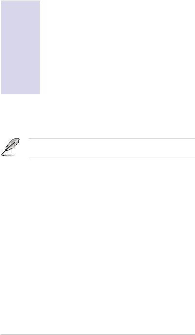
1.3 Front panel features
The barebone server displays a simple yet stylish front panel with easily accessible features. The power and reset buttons, LED indicators, location switch, optical drive, and two USB ports are located on the front panel.
Refer to section 1.6.1 Front panel LEDs for the LED descriptions.
Rack screw |
Hot-swap HDD bay 1-4 |
||||||||
|
|
|
|
|
|
Rack screw |
|||
|
|
|
|
|
|
||||
|
|
|
|
|
|
|
|
|
|
|
|
|
|
|
|
|
|
|
|
|
|
|
|
|
|
|
|
|
|
Optical drive |
HDD LED |
USB ports |
System button and LED |
|
|
HDD Access, LAN, Message LED |
|
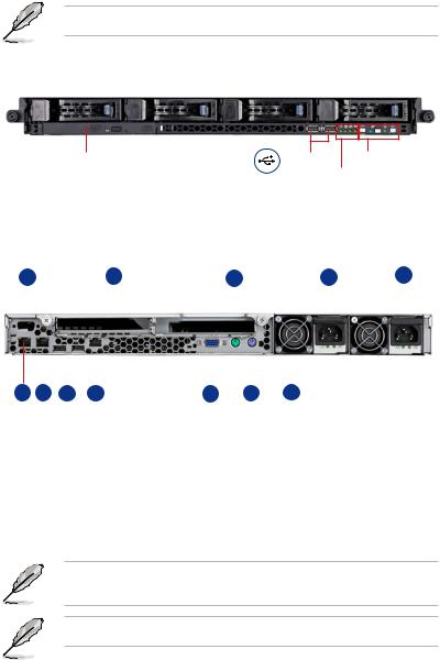
1.4 Rear panel features
The rear panel includes the expansion slot, system power socket, and rear fans. The middle part includes the I/O shield with openings for the rear panel connectors on the motherboard.
6 |
|
10 |
3 |
|
1 |
12 |
||||||||
|
|
|
|
|
|
|
|
|
|
|
|
|
|
|
|
|
|
|
|
|
|
|
|
|
|
|
|
|
|
|
|
|
|
|
|
|
|
|
|
|
|
|
|
|
|
|
|
|
|
|
|
|
|
|
|
|
|
|
|
|
|
|
|
|
|
|
|
|
|
|
|
|
|
|
|
|
|
|
|
|
|
|
|
|
|
|
|
|
|
|
8 |
9 |
5 |
11 |
7 |
4 |
2 |
1. |
Redundant AC power socket |
|
8. |
LAN port1 |
|||
2. |
Rear fans |
|
|
9. |
LAN port2 |
||
3. |
PS/2 mouse port |
|
10. |
2 x Expansion slots |
|||
4. |
PS/2 keyboard port |
|
11.LAN port3(Only supports ASUS |
||||
5. |
USB ports |
|
|
|
IMPI2.0 LAN management card) |
||
6. |
Serial port (for user install self) |
|
12.Second redundant AC power |
||||
7. |
VGA port |
|
|
|
socket (Optional) |
||
The ports for the PS/2 keyboard, PS/2 mouse, USB, VGA, and Gigabit LAN do not appear on the rear panel if motherboard is not present.
Refer to section 1.6.2 Rear panel LEDs for the LED descriptions.
ASUS RS162-E4/RX4 |
1- |

1.5 Internal features
The barebone server includes the basic components as shown.
2 2
4 |
4 |
1 |
7 |
3
5 |
6 |
8
|
9 |
10 |
|
11 |
12 |
|
13 |
|
|
|
|
1. |
PCI-X riser card bracket |
|
8. |
SAS/SATA-II backplane |
|
2. |
Power supply rear fans |
|
9. |
Hot-swap HDD tray 1(port0) |
|
3. |
ASUS DSBF-DR12 motherboard |
10.Hot-swap HDD tray 2(Port1) |
|||
4. |
Redundant power supply |
|
11.Hot-swap HDD tray 2(Port2) |
||
5. |
Device fans (40mm x 56mm) x 2 |
12.Hot-swap HDD tray 2(Port3) |
|||
6. |
System fans (40mm x 28mm) x 5 |
13.Slim optical drive |
|||
7. |
PCI-X and PCI-E riser card |
|
|
|
|
1- |
Chapter 1: Product Introduciton |
1.6 LED information
1.6.1 Front panel LEDs
|
|
|
|
|
|
|
HDD Access LED |
|
|
|
|
|
|
LAN2 LED |
|
|
Power LED |
|||
|
|
|
|
|||
LAN1 LED |
Location LED |
|||||
|
|
|
|
|
||
|
Message LED |
|||||
LED |
Display status |
Description |
Power LED |
ON |
System power ON |
|
|
|
HDD Access LED |
OFF |
No activity |
|
Blinking |
Read/write data into the HDD |
HDD Status access |
ON |
HDD is present |
|
OFF |
No HDD present |
Message LED |
OFF |
System is in normal condition; no incoming event |
|
ON |
ASWM detects a system problem; |
|
|
(Log in to ASWM to identify and resolve) |
Location LED |
OFF |
Normal status |
|
ON |
Location switch is pressed |
|
|
(Press the location switch again to turn off) |
LAN LEDs |
OFF |
No LAN connection |
|
Blinking |
LAN is transmitting or receiving data |
|
ON |
LAN connection is present |
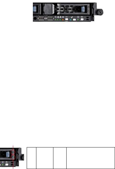
1.6.2 HDD status LED
HDD status LED 1
SCSI |
HDD LED |
status |
Description |
LDE1 |
GREEN |
ON |
SAS/SATA-II HDD power ON |
|
RED |
ON |
SASHDD failure |
|
RED/GREEN |
Blinking |
SAS RAID reset |
LDE2 |
GREEN |
Blinking |
Read/write data into the SAS HDD |
HDD status LED2
ASUS RS162-E4/RX4 |
1- |
1.6.3 Rear panel LEDs
SPEED LED
|
|
|
|
|
ACT/LINK LED |
|
|
|
|
|
|
|
|
|
|
|
|
ACT/LINK LED |
SPEED LED |
|
|
||
Status |
Description |
Status |
Description |
||
OFF |
No link |
OFF |
10Mbps connection |
||
Green |
Linked |
Orange |
100Mbps connection |
||
Blinking |
Linking |
Green |
1000Mbps connection |
||
1- |
Chapter 1: Product Introduciton |

Chapter 2
This chapter lists the hardware setup procedures that you have to perform when installing or removing system components.
Hardware Setup
2.1 Chassis cover
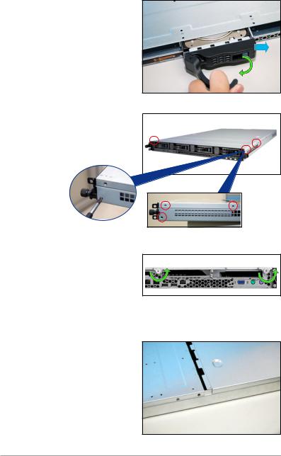
2.1.1 Remove the front cover
1.Push the blue button to the right side and pull the lever outward (see the figure) to remove the hard disk tary.
2.Remove the six screws (refer to the figure for the locations) on
the left and right sides of the front side of the top cover panel
3.Loosen the two screws that scure the top cover panel to the rear panel (refer to the figure for the locations). Please note that do not remove the screws when loosenning them.
4.Push the back cover panel backward until it is half inch away from the front side of the top cover panel.
2- |
Chapter 2: Hardware setup |
5.Push the front side of the top cover panel forward and lift it to expose the cable connectors and slots underneath.
6.Disconnect the LED cable from the connector on the module joint to the front panel.
7.Disconnect the optical drive cable and power cable.
8.Remove the front upper panel and set it aside.
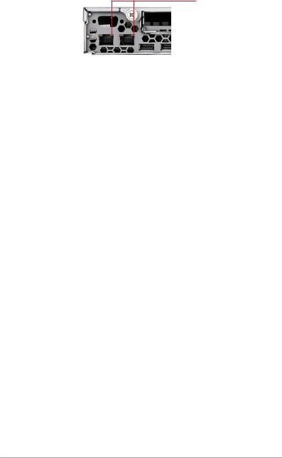
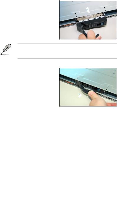
2.1.2Removing the rear cover
1. Loosen the two screws that |
|
screws |
||
|
|
|
|
|
fasten the upper panel cover to |
|
|
|
|
|
|
|
|
|
the real panel cover. Please note |
|
|
|
|
do not remove the screws when |
|
|
|
|
loosening them. |
|
|
|
|
ASUS RS162-E4/RX4 |
2- |

2.Push the back side of the top cover panel backward until it is half inch away from the front upper cover panel.
1/2 inch distance
3. Remove the back top cover panel.
2.1.3 Install the rear cover
Match the upper cover panel to the grooves on the left and right sides.
1.Locate the grooves (see the figure). Push the top cover panel toward the front panel.
2.Match the clips of the top cover panel with the grooves (see the figure), and then clinch. Leave a half inch distence between the front edge of the top cover panel and the real panel.
firmly clinched
match the clips and the grooves
3. Fasten the two screws as shown below.
screws
2- |
Chapter 2: Hardware setup |
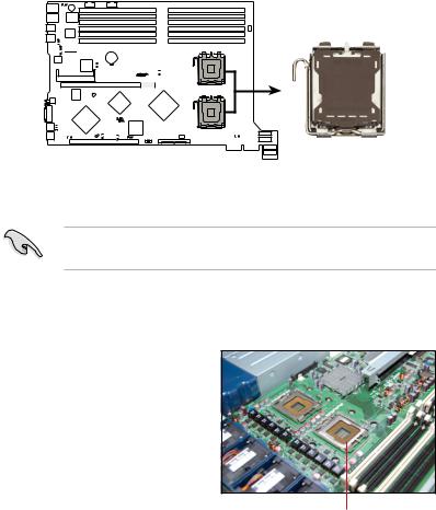
2.2 Install the CPU and heatsink
ASUS RS162-E4/RX4 sever system is powerd by the DSBF-DR12 sever board, which comes with two ZIF type LGA771 CPU sockets. Intel Xeon LGA771 CPU has a Dual-Core architecture with 2M L2 cache.
CPU1
DSBF-DR1 
CPU2
DSBF-DR1 CPU Socket 1
You can install one or two CPUs in this board. When installing only one CPU, please install it in socket 1.
2.2.1 Installing a CPU
To install a CPU:
1.Locate the CPU socket on the motherboard.
CPU1 socket
ASUS RS162-E4/RX4 |
2- |
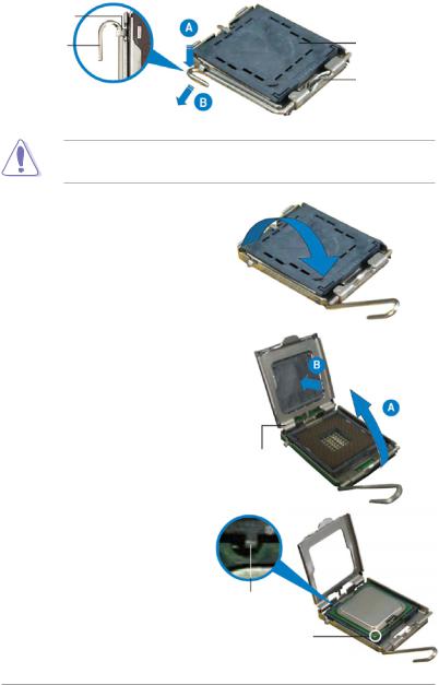
2.Press the load lever with your thumb (A), then move it to the left (B) until it is released from the retention tab.
Retention tab
Load lever |
PnP cap |
This side of the socket box should face yuo
To prevent damage to the socket pins, do not remove the PnP cap unless you are installing a CPU.
3.Lif e th e loa d leve r i n the direction of the arrow.
4.Lift the load plate with you thumb and forefinger (A), then push the PnP cap from the load plate window to remove (B).
5.Position the CPU over the socket, making sure that the gold triangle is on the bottom-left corner of the socket. The socket alignment key should fit into the CPU notch.
load plate
Alignment key Gold triangle mark
2- |
Chapter 2: Hardware setup |
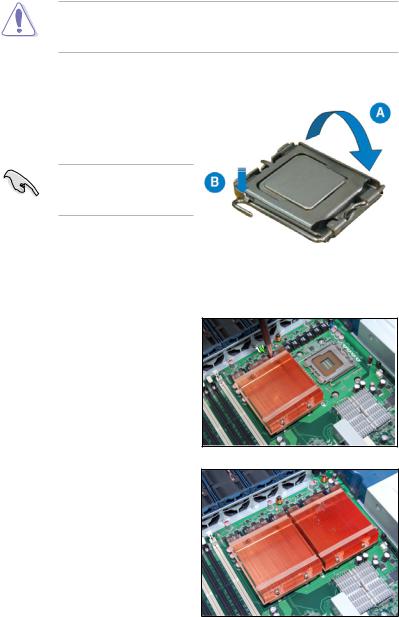
The CPU fits in only one correct orientation. DO NOT force the CPU into the socket to prevent bending the connectors on the socket and damaging the CPU!
6.Close the load plate (A), then push the load lever (B) until it snaps into the retention tab.
If you want to install a second CPU, follow the steps above.
2.2.2 Install the CPU heatsink
To install the CPU heatsink:
1.Put the heatsink on the installed CPU, match the screws with the screw holes on the board.
2.Fasten two screws at a time in a diagonal sequence, and then the other two.
3.Repeat step 1-2 to install the second CPU heatsink.
ASUS RS162-E4/RX4 |
2- |
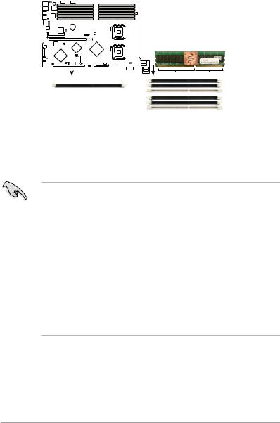
2.3 System memory
2.3.1 Overview
This sever board comes with twelve Double Data Tate 2 (DDR2) Dual Inline Memory Modules (DIMM) sockets, support 240-pin Ecc Registered FBD memory modules.
DSBF-DR1 |
 DIMM_
DIMM_
DIMM_ 1
 DIMM_ 0
 DIMM_
DIMM_  DIMM_ 1
  DIMM_ 0
DSBF-DR1
0-p n FB-DIMM sockets
128 Pins |
112 Pins |
|
DIMM_1 |
|
DIMM_11 |
|
DIMM_10 |
|
DIMM_0 |
|
DIMM_01 |
|
DIMM_00 |
2.3.2 Memory configurations
You may install 512MB, 1GB, 2GB and 4GB fully buffered Ecc registered 533/667 DDR2 DIMMs into the DIMM sockets.
1. Please install DIMMs with the same CAS latency. We recommend that you using DIMMs from the same company.
2.Please do not install SS and DS DIMMs together, otherwise the system might not boot properly.
3.We recommend that you install even number of DIMMs. If you install only one or singular number of DIMMs, or double FBD DIMMs, please install it on the white sockets (such as DIMM_00/DIMM_10).
4.Due to chipset resource allocation and the numbers of PCI devices installed, the system may detected less than 24GB system memory when you installed twelve 2GB DDR2 memory modules.
5.When you install three memory modules, the system is in unsymmetric dual-channel mode, and the system performance is in between the performances of single-channel and dual-channel modes.
2- |
Chapter 2: Hardware setup |
Rank population
|
|
|
|
|
|
|
|
|
|
|
|
|
|
|
|
|
|
|
|
|
|
|
|
|
|
|
|
|
|
|
|
|
|
|
|
|
|
|
|
|
|
|
|
|
|
|
00 DIMM |
|
|
01 DIMM |
|
02 DIMM |
|
10 DIMM |
|
|
11 DIMM |
|
12 DIMM |
|
|
20 DIMM |
|
|
21 DIMM |
|
2231 DIMM |
|
30 DIMM |
|
|
31 DIMM |
|
32 DIMM |
|
||||
|
MCH |
|
|
|
|
|
|
|
|
|
|
|
|
|
|
|
|
|
|||||||||||||||||||||
|
|
|
|
|
|
|
|
|
|
|
|
|
|
|
|
|
|
|
|
|
|
|
|
|
|
|
|
|
|
|
|
|
|
|
|
|
|
|
|
|
|
|
|
|
|
|
|
|
|
|
|
|
|
|
|
|
|
|
|
|
|
|
|
|
|
|
|
|
|
|
|
|
|
|
|
|
|
|
|
|
|
|
|
|
|
|
|
|
|
|
|
|
|
|
|
|
|
|
|
|
|
|
|
|
|
|
|
|
|
|
|
|
|
|
|
|
|
|
|
|
|
|
|
|
|
|
|
|
|
|
|
|
|
|
|
|
|
|
|
|
|
|
|
|
|
|
|
|
|
|
|
|
|
|
|
|
|
|
|
|
|
|
|
|
|
|
|
|
|
|
|
|
|
|
|
|
|
|
|
|
|
|
|
|
|
|
|
|
|
|
|
|
|
|
|
|
|
|
|
|
|
|
|
|
|
|
|
|
|
|
|
|
|
|
|
|
|
|
|
|
|
|
|
|
|
|
|
|
|
|
|
|
|
|
|
|
|
|
|
|
|
|
|
|
|
|
|
|
|
|
|
|
|
|
|
|
|
|
|
|
|
|
|
|
|
|
|
|
|
|
|
|
|
|
|
|
|
|
|
|
|
|
|
|
|
|
|
|
|
|
|
|
|
|
|
|
|
|
|
|
|
|
|
|
|
|
|
|
|
|
|
|
|
|
|
|
|
|
|
|
|
|
|
|
|
|
|
|
|
|
|
|
|
|
|
|
|
|
|
|
|
|
|
|
|
|
|
|
|
|
|
|
|
|
|
|
|
|
|
|
Channel |
|
|
|
|
|
|
|
|
|
|
|
|
|
|
|
|
|
|
|
|
|
|
|
|
|
|
|
|
|
|
|
|
|
|
||||
|
|
0 Slot |
|
1 Slot |
|
|
0 Slot |
|
1 Slot |
2 Slot |
|
|
0 Slot |
|
1 Slot |
2 Slot |
|
0 Slot |
|
1 Slot |
2 Slot |
|
|||||||||||||||||
|
|
|
|
|
|
|
|
2 Slot |
|
|
|
|
|
|
|
|
|||||||||||||||||||||||
|
|
|
|
|
|
|
|
|
|
|
|
|
|
|
|
|
|
|
|
|
|
|
|
|
|
|
|
|
|
|
|
|
|
||||||
|
|
|
|
|
|
|
|
|
|
|
|
|
|
|
|
|
|
|
|
|
|
|
|
|
|
|
|
|
|
|
|
|
|
||||||
|
|
|
|
|
|
|
|
|
Ch:0 |
|
|
|
|
Ch:1 |
|
|
|
|
|
Ch:2 |
|
|
|
|
Ch:3 |
|
|
||||||||||||
|
|
|
|
|
|
|
|
|
|
|
|
|
|
|
|
|
|
|
|
|
|
|
|
|
|
|
|
|
|
|
|
|
|
|
|||||
DIMM installation reference table |
|
|
|
|
|
|
|
|
|
|
|
|
|
|
|
|
|
|
|
||||||||||||||||||||
|
|
|
|
|
|
|
|
|
|
|
|
|
|
|
|
|
|
|
|
|
|
|
|
|
|
|
|
|
|
|
|
|
|
|
|
|
|
|
|
Numbers |
of |
Slots options |
|
|
|
|
|
|
|
|
|
|
|
|
|
|
|
|
|
|
|
|
|
|
|
|
|
|
|
|
|
|
|
||||||
DIMM |
|
|
|
|
|
|
|
|
|
|
|
|
|
|
|
|
|
|
|
|
|
|
|
|
|
|
|
|
|
|
|
|
|
|
|
|
|
|
|
1 |
|
DIMM_00 |
|
|
|
|
|
|
|
|
|
|
|
|
|
|
|
|
|
|
|
|
|
|
|
|
|
|
|
|
|
|
|
||||||
2 |
|
DIMM_00,DIMM_10 |
|
|
|
|
|
|
|
|
|
|
|
|
|
|
|
|
|
|
|
|
|
|
|
|
|
|
|
||||||||||
4 |
|
DIMM_00,DIMM_10,DIMM_20,DIMM_30 |
|
|
|
|
|
|
|
|
|
|
|
|
|
|
|
|
|||||||||||||||||||||
6 |
|
DIMM_00,DIMM_10,DIMM_20,DIMM_30,DIMM_01,DIMM_11 |
|
|
|
|
|
|
|||||||||||||||||||||||||||||||
8 |
|
DIMM_00,DIMM_10,DIMM_20,DIMM_30,DIMM_01,DIMM_11, |
|
|
|
|
|
|
|||||||||||||||||||||||||||||||
|
|
|
DIMM_21,DIMM_31 |
|
|
|
|
|
|
|
|
|
|
|
|
|
|
|
|
|
|
|
|
|
|
|
|
|
|
|
|||||||||
10 |
|
DIMM_00,DIMM_10,DIMM_20,DIMM_30,DIMM_01,DIMM_11, |
|
|
|
|
|
|
|||||||||||||||||||||||||||||||
|
|
|
DIMM_21,DIMM_31,DIMM_02,DIMM_12 |
|
|
|
|
|
|
|
|
|
|
|
|
|
|
|
|
||||||||||||||||||||
12 |
|
DIMM_00,DIMM_10,DIMM_20,DIMM_30,DIMM_01,DIMM_11, |
|
|
|
|
|
|
|||||||||||||||||||||||||||||||
|
|
|
DIMM_21,DIMM_31,DIMM_02,DIMM_12,DIMM_22,DIMM_32 |
|
|
|
|
|
|
||||||||||||||||||||||||||||||
•DIMMs in pair means two DIMMs with the same configuration.
•For better performance, same configuration DIMMs should be installed on the same slot number for each channel. For example, you may install the same type of DIMMs in DIMM_00, DIMM_10, DIMM_20, and DIMM_30.
ASUS RS162-E4/RX4 |
2- |
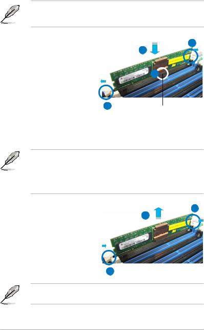
2.3.3 Installing a DIMM
To install a DIMM:
Unplug the power supply before adding or removing DIMMs or other system components. Failure to do so can cause severe damage to both the motherboard and the components.
1. |
Un l o c k a DI M M s o c k e t b y |
|
pressing the retaining clips |
|
outward. |
2. |
Align a DIMM on the socket |
|
such that the notch on the |
|
DIMM matches the break on the |
|
socket. |
3. |
Firmly insert the DIMM into the |
socket until the retaining clips |
1 |
|
|
snap back in place and the DIMM |
|
is properly seated. |
|
1
3
2
DDR2 DIMM notch
· A DDR2 DIMM is keyed with a notch so that it fits in only one direction. Do not force a DIMM into a socket to aviod damaging the DIMM.
·The DDR2 DIMM sockets do not support DDR DIMMs. DO not install DDR DIMMs to the DDR2 DIMM sockets.
2.3.4 Removing a DIMM |
1 |
|
|
1. S i m u l t a n e o u s l y p r e s s t g e |
2 |
retaining clips outward to unlock the DIMM.
2.Remove the DIMM from the socket.
1
Support the DIMM lightly with your fingers when pressing the retaining clips. The DIMM might get damaged when it flips out with extra force.
2-10 |
Chapter 2: Hardware setup |
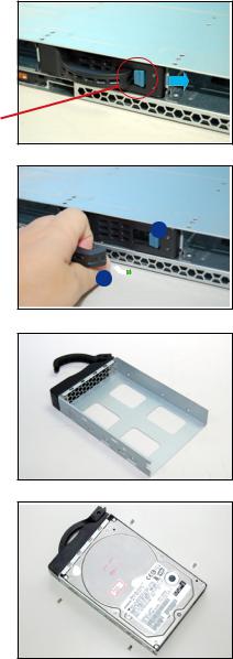
2.4 Hot-swap hard disk drives
To install a hot-swap HDD:
1.Release a drive tray by pushing the spring lock to the right, then pulling the tray lever outward. The drive tray ejects slightly after you pull out the lever.
retaining button
2.Firmly hold the tray lever and pull the drive tray out of the bay.
1
2
3.Take note of the drive tray holes. Each side has three holes to fit different types of hard disk drives. Use two screws on each side to secure the hard disk drive.
4.Place a hard disk drive on the tray, then secure it four screws.
ASUS RS162-E4/RX4 |
2-11 |
5.Cearfully insert the drive tray and push it all the way to the depth of the bay until just a small fraction of the tray edge prottrudes.
When installed, the SAS/SATA connector on the drive connects to the SAS/SATA connector on the backplane. Refer to the section 2.7 SAS/ SATA backplane cabling for more information.
6.Push the tary level until clicks, and secures the drive tray in place. The drive tray is correctly placed when its front edge aligns with the bay edge.
7.Refer step 1 to 6 if you wish to install a second , third and/or fourth drive.
2-12 |
Chapter 2: Hardware setup |
 Loading...