


 Loading...
RS160-E5
1U Rackmount Server
User Guide

E3694
First Edition V1
March 2008
Copyright © 2008 ASUSTeK COMPUTER INC. All Rights Reserved.
No part of this manual, including the products and software described in it, may be reproduced, transmitted, transcribed, stored in a retrieval system, or translated into any language in any form or by any means, except documentation kept by the purchaser for backup purposes, without the express written permission of ASUSTeK COMPUTER INC. (“ASUS”).
ASUS provides this manual “as is” without warranty of any kind, either express or implied, including but not limited to the implied warranties or conditions of merchantability or fitness for a particular purpose. In no event shall ASUS, its directors, officers, employees, or agents be liable for any indirect, special, incidental, or consequential damages (including damages for loss of profits, loss of business, loss of use or data, interruption of business and the like), even if ASUS has been advised of the possibility of such damages arising from any defect or error in this manual or product.
Specifications and information contained in this manual ae furnished for informational use only, and are subject to change at any time without notice, and should not be construed as a commitment by ASUS. ASUS assumes no responsibility or liability for any errors or inaccuracies that may appear in this manual, including the products and software described in it.
Product warranty or service will not be extended if: (1) the product is repaired, modified or altered, unless such repair, modification of alteration is authorized in writing by ASUS; or (2) the serial number of the product is defaced or missing.
Products and corporate names appearing in this manual may or may not be registered trademarks or copyrights of their respective companies, and are used only for identification or explanation and to the owners’ benefit, without intent to infringe.
ii

Contents
Contents....................................................................................................... |
iii |
Notices........................................................................................................ |
vii |
Safety information..................................................................................... |
viii |
About this guide.......................................................................................... |
ix |
Chapter 1: |
Product introduction |
|
|
1.1 |
System package contents............................................................ |
1-2 |
|
1.2 |
Serial number label....................................................................... |
1-2 |
|
1.3 |
System specifications.................................................................. |
1-3 |
|
1.4 |
Front panel features..................................................................... |
1-5 |
|
1.5 |
Rear panel features...................................................................... |
1-5 |
|
1.6 |
Internal features............................................................................ |
1-6 |
|
1.7 |
LED information............................................................................ |
1-7 |
|
|
1.7.1 |
Front panel LEDs............................................................. |
1-7 |
|
1.7.2 |
LAN (RJ-45) LEDs........................................................... |
1-7 |
|
1.7.3 |
HDD status LED.............................................................. |
1-8 |
Chapter 2: |
Hardware setup |
|
|
2.1 |
Chassis cover............................................................................... |
2-2 |
|
|
2.1.1 |
Removing the front cover................................................ |
2-2 |
|
2.1.2 |
Removing the rear cover................................................. |
2-4 |
|
2.1.3 |
Installing the top cover..................................................... |
2-5 |
2.2 |
Central Processing Unit (CPU).................................................... |
2-6 |
|
|
2.2.1 |
Installing the CPU............................................................ |
2-6 |
|
2.2.2 |
Installing the CPU heatsink and airduct........................... |
2-9 |
2.3 |
System memory.......................................................................... |
2-10 |
|
|
2.3.1 |
Overview........................................................................ |
2-10 |
|
2.3.2 |
Memory configurations.................................................. |
2-10 |
|
2.3.3 |
Memory mirroring and sparing technology.................... |
2-12 |
|
2.3.4 |
Installing a DIMM........................................................... |
2-14 |
|
2.3.5 |
Removing a DIMM......................................................... |
2-14 |
2.4 |
Hard disk drives.......................................................................... |
2-15 |
|
2.5 |
Expansion slot............................................................................ |
2-17 |
|
|
2.5.1 |
Installing an expansion card to the riser card bracket... |
2-17 |
|
2.5.2 |
Replacing the riser card (optional)................................. |
2-18 |
|
2.5.3 |
Reinstalling the riser card bracket................................. |
2-19 |
iii

Contents
|
2.5.4 |
Installing ASUS PIKE RAID card (optional)................... |
2-20 |
|
2.5.5 |
Configuring an expansion card...................................... |
2-21 |
2.6 |
Cable connections...................................................................... |
2-22 |
|
2.7 |
SATAII/SAS backplane cabling.................................................. |
2-23 |
|
2.8 |
Removable components............................................................ |
2-24 |
|
|
2.8.1 |
System fans................................................................... |
2-24 |
|
2.8.2 |
Power supply module.................................................... |
2-27 |
|
2.8.3 |
Optical drive................................................................... |
2-28 |
|
2.8.4 |
Motherboard.................................................................. |
2-31 |
Chapter 3: |
Installation options |
|
|
3.1 |
Rackmount rail kit items.............................................................. |
3-2 |
|
3.2 |
Rack rails assembly..................................................................... |
3-2 |
|
3.3 |
Attaching the rails to the rack..................................................... |
3-3 |
|
3.4 |
Rackmounting the server............................................................. |
3-4 |
|
Chapter 4: |
Motherboard Info |
|
|
4.1 |
Motherboard layout...................................................................... |
4-2 |
|
4.2 |
Jumpers |
......................................................................................... |
4-4 |
4.3 |
Internal connectors...................................................................... |
4-9 |
|
Chapter 5: |
BIOS setup |
|
|
5.1 |
Managing and updating your BIOS............................................. |
5-2 |
|
|
5.1.1 |
Creating a bootable floppy disk....................................... |
5-2 |
|
5.1.2 |
AFUDOS utility................................................................ |
5-3 |
|
5.1.3 |
ASUS CrashFree BIOS 3 utility....................................... |
5-6 |
5.2 |
BIOS setup program..................................................................... |
5-7 |
|
|
5.2.1 |
BIOS menu screen.......................................................... |
5-8 |
|
5.2.2 |
Menu bar......................................................................... |
5-8 |
|
5.2.3 |
Navigation keys............................................................... |
5-8 |
|
5.2.4 |
Menu items...................................................................... |
5-9 |
|
5.2.5 |
Sub-menu items.............................................................. |
5-9 |
|
5.2.6 |
Configuration fields.......................................................... |
5-9 |
|
5.2.7 |
Pop-up window................................................................ |
5-9 |
|
5.2.8 |
Scroll bar......................................................................... |
5-9 |
|
5.2.9 |
General help.................................................................... |
5-9 |
iv

Contents
5.3 |
Main menu................................................................................... |
5-10 |
|
|
5.3.1 |
System Time.................................................................. |
5-10 |
|
5.3.2 |
System Date]................................................................. |
5-10 |
|
5.3.3 |
Legacy Diskette A.......................................................... |
5-10 |
|
5.3.4 |
SATA1–6; PATA Master/Slave........................................ |
5-11 |
|
5.3.5 |
IDE Configuration.......................................................... |
5-13 |
|
5.3.6 |
System Information........................................................ |
5-14 |
5.4 |
Advanced menu.......................................................................... |
5-15 |
|
|
5.4.1 |
USB Configuration......................................................... |
5-15 |
|
5.4.2 |
CPU Configuration......................................................... |
5-17 |
|
5.4.3 |
Chipset.......................................................................... |
5-19 |
|
5.4.4 |
Onboard Device Configuration...................................... |
5-21 |
|
5.4.5 |
PCIPnP.......................................................................... |
5-22 |
5.5 |
Server menu................................................................................ |
5-23 |
|
|
5.5.1 |
ASF Support.................................................................. |
5-23 |
|
5.5.2 |
Remote Access Configuration....................................... |
5-23 |
5.6 |
Power menu................................................................................ |
5-25 |
|
|
5.6.1 |
ACPI 2.0 Support........................................................... |
5-25 |
|
5.6.2 |
ACPI APIC Support....................................................... |
5-25 |
5.7 |
Boot menu................................................................................... |
5-28 |
|
|
5.7.1 |
Boot Device Priority....................................................... |
5-28 |
|
5.7.2 |
Boot Settings Configuration........................................... |
5-29 |
|
5.7.3 |
Security.......................................................................... |
5-30 |
5.8 |
Exit menu..................................................................................... |
5-32 |
|
Chapter 6: |
RAID configuration |
|
|
6.1 |
Setting up RAID............................................................................ |
6-2 |
|
|
6.1.1 |
RAID definitions............................................................... |
6-2 |
|
6.1.2 |
Installing hard disk drives................................................ |
6-3 |
|
6.1.3 |
Setting the RAID item in BIOS......................................... |
6-3 |
|
6.1.4 |
RAID configuration utilities.............................................. |
6-3 |
6.2 |
LSI Software RAID Configuration Utility..................................... |
6-4 |
|
|
6.2.1 |
Creating a RAID 0 or RAID 1 set..................................... |
6-5 |
|
6.2.2 |
Creating a RAID 10 set................................................... |
6-11 |
|
6.2.3 |
Adding or viewing a RAID configuration........................ |
6-15 |

Contents
|
6.2.4 |
Initializing the logical drives........................................... |
6-18 |
|
6.2.5 |
Rebuilding failed drives................................................. |
6-23 |
|
6.2.6 |
Checking the drives for data consistency...................... |
6-25 |
|
6.2.7 |
Deleting a RAID configuration....................................... |
6-28 |
|
6.2.8 |
Selecting the boot drive from a RAID set...................... |
6-29 |
|
6.2.9 |
Enabling the WriteCache............................................... |
6-30 |
6.3 |
Intel® Matrix Storage Manager Option ROM Utility.................. |
6-31 |
|
|
6.3.1 |
Creating a RAID 0 set (Stripe)....................................... |
6-32 |
|
6.3.2 |
Creating a RAID 1 set (Mirror)....................................... |
6-34 |
|
6.3.3 |
Creating a RAID 10 set (Stripe + Mirror)....................... |
6-35 |
|
6.3.4 |
Creating a RAID 5 set (Parity)....................................... |
6-36 |
|
6.3.5 |
Deleting a RAID set....................................................... |
6-37 |
|
6.3.6 |
Resetting disks to Non-RAID......................................... |
6-38 |
|
6.3.7 |
Exiting the Intel® Matrix Storage Manager..................... |
6-38 |
Chapter 7: |
Driver installation |
|
|
7.1 |
RAID driver installation................................................................ |
7-2 |
|
|
7.1.1 |
Creating a RAID driver disk............................................. |
7-2 |
|
7.1.2 |
Installing the RAID controller driver................................. |
7-5 |
7.2 |
Intel® chipset device installation............................................... |
7-13 |
|
7.3 |
LAN driver installation............................................................... |
7-16 |
|
7.4 |
VGA driver installation............................................................... |
7-19 |
|
|
7.4.1 |
Windows® Server .......................................................... |
7-19 |
7.5 |
Management applications and utilities installation................. |
7-21 |
|
|
7.5.1 |
Running the support CD................................................ |
7-21 |
|
7.5.2 |
Drivers menu................................................................. |
7-21 |
|
7.5.3 |
Management Software menu........................................ |
7-22 |
|
7.5.4 |
Utilities menu................................................................. |
7-22 |
|
7.5.5 |
Contact information....................................................... |
7-22 |
vi

Notices
Federal Communications Commission Statement
This device complies with Part 15 of the FCC Rules. Operation is subject to the following two conditions:
•This device may not cause harmful interference, and
•This device must accept any interference received including interference that may cause undesired operation.
This equipment has been tested and found to comply with the limits for a Class
A digital device, pursuant to Part 15 of the FCC Rules. These limits are designed to provide reasonable protection against harmful interference in a residential installation. This equipment generates, uses and can radiate radio frequency energy and, if not installed and used in accordance with manufacturer’s instructions, may cause harmful interference to radio communications. However, there is
no guarantee that interference will not occur in a particular installation. If this equipment does cause harmful interference to radio or television reception, which can be determined by turning the equipment off and on, the user is encouraged to try to correct the interference by one or more of the following measures:
•Reorient or relocate the receiving antenna.
•Increase the separation between the equipment and receiver.
•Connect the equipment to an outlet on a circuit different from that to which the receiver is connected.
•Consult the dealer or an experienced radio/TV technician for help.
WARNING! The use of shielded cables for connection of the monitor to the graphics card is required to assure compliance with FCC regulations. Changes or modifications to this unit not expressly approved by the party responsible for compliance could void the user’s authority to operate this equipment.
Canadian Department of Communications Statement
This digital apparatus does not exceed the Class A limits for radio noise emissions from digital apparatus set out in the Radio Interference Regulations of the Canadian Department of Communications.
This Class A digital apparatus complies with Canadian ICES-003.
vii
Safety information
Electrical Safety
•Before installing or removing signal cables, ensure that the power cables for the system unit and all attached devices are unplugged.
•To prevent electrical shock hazard, disconnect the power cable from the electrical outlet before relocating the system.
•When adding or removing any additional devices to or from the system, ensure that the power cables for the devices are unplugged before the signal cables are connected. If possible, disconnect all power cables from the existing system before you add a device.
•If the power supply is broken, do not try to fix it by yourself. Contact a qualified service technician or your dealer.
Operation Safety
•Any mechanical operation on this server must be conducted by certified or experienced engineers.
•Before operating the server, carefully read all the manuals included with the server package.
•Before using the server, make sure all cables are correctly connected and the power cables are not damaged. If any damage is detected, contact your dealer as soon as possible.
•To avoid short circuits, keep paper clips, screws, and staples away from connectors, slots, sockets and circuitry.
•Avoid dust, humidity, and temperature extremes. Place the server on a stable surface.
This product is equipped with a three-wire power cable and plug for the user’s safety. Use the power cable with a properly grounded electrical outlet to avoid electrical shock.
Lithium-Ion Battery Warning
CAUTION! Danger of explosion if battery is incorrectly replaced.
Replace only with the same or equivalent type recommended by the manufacturer. Dispose of used batteries according to the manufacturer’s instructions.
CD-ROM Drive Safety Warning
CLASS 1 LASER PRODUCT
Heavy System
CAUTION! This server system is heavy. Ask for assistance when moving or carrying the system.
viii

About this guide
Audience
This user guide is intended for system integrators, and experienced users with at least basic knowledge of configuring a server.
Contents
This guide contains the following parts:
1.Chapter 1: Product Introduction
This chapter describes the general features of the server, including sections on front panel and rear panel specifications.
2.Chapter 2: Hardware setup
This chapter lists the hardware setup procedures that you have to perform when installing or removing system components.
3.Chapter 3: Installation options
This chapter describes how to install optional components into the barebone server.
4.Chapter 4: Motherboard information
This chapter gives information about the motherboard that comes with the server. This chapter includes the motherboard layout, jumper settings, and connector locations.
5.Chapter 5: BIOS information
This chapter tells how to change system settings through the BIOS Setup menus and describes the BIOS parameters.
6.Chapter 6: RAID configuration
This chapter tells how to change system settings through the BIOS Setup menus. Detailed descriptions of the BIOS parameters are also provided.
7Chapter 7: Driver installation
This chapter provides instructions for installing the necessary drivers for different system components.
ix
Conventions
To make sure that you perform certain tasks properly, take note of the following symbols used throughout this manual.
DANGER/WARNING: Information to prevent injury to yourself when trying to complete a task.
CAUTION: Information to prevent damage to the components when trying to complete a task.
IMPORTANT: Instructions that you MUST follow to complete a task.
NOTE: Tips and additional information to help you complete a task.
Typography
Bold text |
Indicates a menu or an item to select. |
Italics |
Used to emphasize a word or a phrase. |
<Key> |
Keys enclosed in the less-than and greater- |
|
than sign means that you must press the |
|
enclosed key. |
|
Example: <Enter> means that you must press |
|
the Enter or Return key. |
<Key1+Key2+Key3> |
If you must press two or more keys |
|
simultaneously, the key names are linked with |
|
a plus sign (+). |
|
Example: <Ctrl+Alt+D> |
Command |
Means that you must type the command |
|
exactly as shown, then supply the required |
|
item or value enclosed in brackets. |
|
Example: At the DOS prompt, type the |
|
command line: format A:/S |
References |
|
Refer to the following sources for additional information, and for product and software updates.
1.ASUS Server Web-based Management (ASWM) user guide
This manual tells how to set up and use the proprietary ASUS server management utility.
2.ASUS websites
The ASUS websites worldwide provide updated information for all ASUS hardware and software products. Refer to the ASUS contact information.
Chapter 1
This chapter describes the general features of the chassis kit. It includes sections on front panel and rear panel specifications.
ASUS RS160-E5
Product introduction
1-
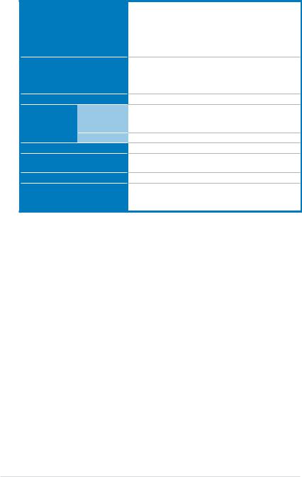
1.1System package contents
Check your system package for the following items.
Model Name |
RS160-E5 |
Chassis |
ASUS R10 1U Rackmount Chassis |
Motherboard |
ASUS DSAN-DX/RS160-E5 Server Board |
Component |
1 x 460W 80+ Single Power Supply |
|
1 x SATAII/SAS Backplane (ASUS BP4LX-R10) with 4 x SATA Cables |
|
4 x hot-swap HDD trays |
|
1 x Riser card (ASUS PCIE16X2-R10) with 1 x PCIe x8 slot and 1 x |
|
PCIe x16 slot |
|
1 x Front I/O Board (ASUS FPB-AR14) |
|
6 x System Fans (1 x 56mm; 5 x 28mm) |
|
1 x Air Duct |
Accessories |
2 x CPU Heatsinks (optional) |
|
1 x RS160-E5 User’s Guide |
|
1 x ASUS ASWM 2.0 User’s Guide |
|
1 x RS160-E5 Support CD (including ASWM*) |
|
1 x Bag of Screws |
|
1 x AC Power Cable |
|
1 x Fixed Rackmount Kit |
Optional Items CA eTrust Anti-virus Software CD
ASUS ASMB-iKVM Remote management card
ASUS PIKE 1064E SAS RAID card
*ASUS System Web-based Management
If any of the above items is damaged or missing, contact your retailer.
*The system does not include a USB floppy drive. You may have to use a USB floppy drive when creating a SATA RAID driver disk. Refer to Chapter 7 for details.
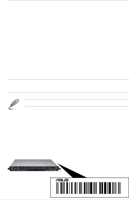
1.2Serial number label
Before requesting support from the ASUS Technical Support team, you must take note of the product’s serial number containing 12 characters such as xxxxxxxxxxxx. See the figure below.
With the correct serial number of the product, ASUS Technical Support team members can then offer a quicker and satisfying solution to your problems.
RS160-E5
xxxxxxxxxxxx
1-2 |
Chapter 1: Product introduction |
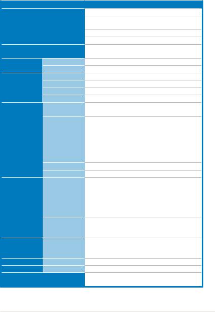
1.3System specifications
The ASUS RS160-E5 is a 1U barebone server system featuring the ASUS DSAN-DX/RS160-E5 server board. The server supports Intel® LGA771 Xeon® 5100 / 5200 / 5300 / 5400 Series processors with EM64T technology, plus other latest technologies through the chipsets onboard.
Model Name
Processor / System Bus
Core Logic
ASUS Features |
Smart Fan |
|
ASWM2.0 |
||
|
||
|
Total Slots |
|
Memory |
Capacity |
|
Memory Type |
||
|
||
|
Memory Size |
|
|
Total PCI/PCI-X/ |
|
|
PCI-E Slots |
Expansion Slots Slot Type
Additional Slot 1
Additional Slot 2
SATA Controller
Storage
SAS Controller
I = internal HDD Bays A or S will be
hot-swappable
Networking LAN
Graphic VGA
Auxiliary Storage FDD / CD / DVD
RS160-E5
2 x Socket LGA771
Intel® Xeon® 5100 / 5200 / 5300 / 5400 Series
processors
Quad-Core/Dual-Core
FSB 1333/1066 MHz EM64T
Intel® 5100 Memory Controller Hub (MCH)
Intel® ICH9R
√
√
6 (Dual-Channel)
Maximum up to 24GB
DDR2 533 / 667 Registered, ECC
512MB, 1GB, 2GB and 4GB
2
Default Riser Card:
1 x PCIe x16 slot (x8 link) (Full-Height/Half- Length) + 1 x PCIe x8 slot (x8 link) (Half-Height/
Half-Length)
Configuration Option:
1 x PCIe x16 slot (x16 link) (Full-Height/Half-
Length)
1 x SO-DIMM socket for optional ASMB3-iKVM
1 x Proprietary Slot for optional ASUS PIKE
Intel® ICH9R:
6 x SATA 300MB/s ports*
Intel Matrix Storage (for Windows only)
-Supports software RAID 0, 1, 5 & 10 LSI Mega RAID (for Windows and Linux):
-Supports software RAID 0, 1 & 10
Optional:
ASUS PIKE 1064E 4 port SAS RAID card - Supports firmware RAID 0, 1 & 1E
4 x Hot-swap HDD Bays
2 x Broadcom® BCM5721 PCI-E GbE LANs
XGI Z9S VGA Controller / 32MB DDRII SDRAM
1 x Slim-type Optical Device Bay
Options: No Device / DVD-ROM / DVD-RW
(continued on the next page)
ASUS RS160-E5 |
1-3 |
Onboard I/O
OS Support
Anti-virus Software
|
Out of Band |
Management |
Remote |
Solution |
Hardware |
|
Software |
Dimension (HH x WW x DD)
Net Weight Kg (CPU, DRAM & HDD not includeed)
Power Supply
Environment
1 x External Serial Port
3 x RJ-45 ports (1 for incoming ASUS ASMB3-iKVM) 4 x USB 2.0 ports (Front x 2, Rear x 2)
1 x VGA port
1 x PS/2 keyboard port
1 x PS/2 mouse port
Windows® Server 2003 R2 Enterprise 32/64-bit RedHat® Enterprise Linux AS5.0 32/64-bit SuSE® Linux Enterprise Server 10.0 32/64-bit
(Subject to change without any notice)
CA® eTrust™ 7.1 anti-virus software (Optional)
ASMB3-SOL (Optional)
ASUS ASWM 2.0 and SNMP
600mm x 444mm x 43.6mm
18 Kg
460W 80+ Single Power Supply
Operation temperature: 10°C~35°C Non operation temperature: -40°C~70°C
Non operation humidity: 20%~90% (Non-condensing)
*Specifications are subject to change without notice.
1-4 |
Chapter 1: Product introduction |
1.4Front panel features
The barebone server displays a simple yet stylish front panel with easily accessible features. The power and reset buttons, LED indicators, optical drive, and two USB ports are located on the front panel.
Refer to section 1.7.1 Front panel LEDs for the LED descriptions.
Rack screw |
Hot-swap HDD bays |
Rack screw |
|||||
|
|
|
|
|
|
|
|
|
|
|
|
|
|
|
|
|
|
|
|
|
|
|
|
|
|
|
|
|
|
|
|
|
|
|
|
|
|
|
|
|
|
|
|
|
|
|
|
|
|
|
|
|
|
|
|
|
|
|
|
|
|
|
|
|
|
|
|
|
|
|
|
|
||
Optical drive |
USB ports |
|
|
|
|
|
|
|
Power |
|||||||
HDD Access LED |
|
|
|
|
|
|
|
|
|
|||||||
|
|
|
|
|
|
|
|
|
|
button |
||||||
|
|
|
|
|
||||||||||||
|
|
LAN2 LED |
|
|
|
|
|
|
|
|
|
|
||||
|
|
|
|
|
|
|
|
|
|
Power |
||||||
|
|
LAN1 LED |
|
|
|
|
|
|
|
|||||||
|
|
|
|
|
|
|
LED |
|||||||||
|
|
Message LED |
|
|
|
|
|
|
|
|||||||
|
|
|
|
|
|
|
|
|
|
|||||||
|
|
Reset button |
|
|
|
|
|
|
|
|
||||||
|
|
|
|
|
|
|
|
|
|
|||||||
|
|
Location LED |
|
|
|
|
|
|
|
|
||||||
|
|
|
|
|
|
|
|
|
|
|||||||
|
|
Location switch |
|
|
|
|
|
|
|
|
||||||
|
|
|
|
|
|
|
|
|
|
|||||||
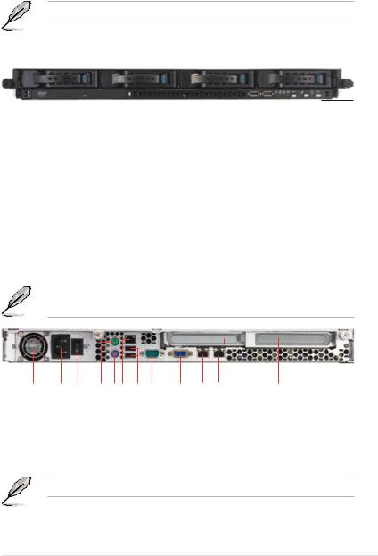
1.5Rear panel features
The rear panel includes the expansion slots, system power socket, and rear fans.
The middle part includes the I/O shield with openings for the rear panel connectors on the motherboard.
The ports for the PS/2 keyboard, PS/2 mouse, USB, VGA, serial port, and Gigabit LAN do not appear on the rear panel if motherboard is not present.
fansupplyPower |
connectorcordPower |
switchsupplyPower |
port mouse PS/2
port keyboard PS/2
port* LAN
portSerial portsUSB |
portVGA |
port2 LAN port1 LAN |
Expansion |
|
slots |
*This port is for incoming ASUS ASMB3-iKVM controller card only.
ASUS RS160-E5 |
1-5 |
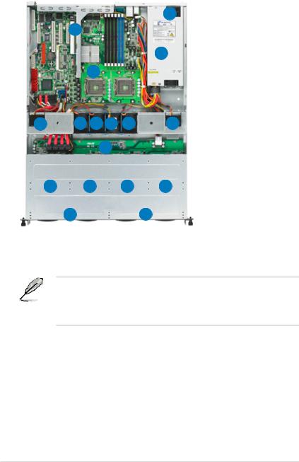
1.6Internal features
The barebone server includes the basic components as shown.
2
1
4
3
5 |
5 |
5 |
6 |
5 |
5 |
|
|
|
7 |
|
|
8 |
|
9 |
|
10 |
11 |
13 |
|
|
|
|
12 |
1.PCIe x16 and x8 slot Riser Card (at x8 link)
2.Power fans
3.ASUS DSAN-DX/ RS160-E5 server board
4.Power supply
5.5 x 4028 system fan
6.1 x 4056 system fan
7.SATAII/SAS backplane
8.Hot-swap HDD tray 1 -
Connects to SATA1 port
(Port 0)
9.Hot-swap HDD tray 2 - Connects to SATA2 port
(Port 1)
10.Hot-swap HDD tray 3 -
Connects to SATA3 port
(Port 2)
11.Hot-swap HDD tray 4 - Connects to SATA4 port (Port 3)
12.Front I/O board (hidden)
13.Slim-type optical drive bay - Connects to SATA5 port (Port 4)
• The barebone server does not include a floppy disk drive. Connect a USB floppy disk drive to any of the USB ports on the front or rear panel if you need to use a floppy disk.
•Only ASUS DVD-ROMs fit the optical drive bay.
1-6 |
Chapter 1: Product introduction |
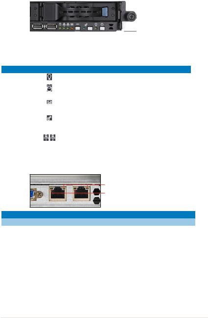
1.7LED information
1.7.1Front panel LEDs
|
|
|
|
|
|
|
|
|
|
|
|
|
|
|
|
|
|
|
|
|
|
|
|
|
|
HDD Access LED |
|
|
|
|
|
|
Power LED |
|||||
|
|
|
|
|
|
|||||||
|
|
|
|
|
|
|
|
|
Location LED |
|||
|
|
LAN2 LED |
|
|
||||||||
|
|
|
Message LED |
|||||||||
|
|
|
|
|
|
|
||||||
|
|
LAN1 LED |
|
|
|
|
|
|
||||
|
|
|
|
|
|
|
||||||
LED |
Icon Display status |
Description |
||||||||||
Power LED |
|
|
|
|
|
|
ON |
System power ON |
||||
HDD Access LED |
|
|
|
|
|
|
OFF |
No activity |
|
|||
|
|
|
|
|
Blinking |
Read/write data from/into the HDD |
||||||
|
|
|
|
|
|
|
||||||
Message LED |
|
|
|
|
|
|
OFF |
System is normal; no incoming event |
|
|||
|
|
|
|
|
Blinking |
ASWM indicates a HW monitor event |
||||||
|
|
|
|
|
|
|
||||||
|
|
|
|
|
|
|
|
OFF |
Normal status |
|
||
Location LED |
|
|
|
|
|
|
ON |
Location switch is pressed |
||||
|
|
|
|
|
|
|
|
|
|
(Press the location switch again to turn off) |
||
|
|
|
|
|
|
|
|
OFF |
No LAN connection |
|
||
LAN LEDs |
|
|
|
|
|
Blinking |
LAN is transmitting or receiving data |
|||||
|
|
|
|
|
|
|
|
ON |
LAN connection is present |
|||
1.7.2LAN (RJ-45) LEDs
SPEED LED
ACT/LINK LED
ACT/LINK LED |
|
SPEED LED |
|
Status |
Description |
Status |
Description |
OFF |
No link |
OFF |
10 Mbps connection |
GREEN |
Linked |
ORANGE |
100 Mbps connection |
BLINKING |
Data activity |
GREEN |
1 Gbps connection |
ASUS RS160-E5 |
1-7 |
1.7.3HDD status LED
HDD Status LED
HDD Activity LED
SATAII/SAS HDD LED Description
|
|
GREEN |
ON |
SATAII/SAS HDD power ON |
|
|
HDD |
RED |
ON |
SATAII/SAS HDD not present |
|
|
|
|
1. HDD has failed and should be |
|
|
|
Status |
|
|
swapped immediately (slow blinking, |
|
|
LED |
RED |
Blinking |
2 times/sec) |
|
|
|
|
|
2. RAID rebuilding (fast blinking, |
|
|
|
|
|
10 times/sec) |
|
|
HDD |
|
|
Read/write data from/into the SATAII/ |
|
|
Activity |
GREEN |
Blinking |
||
|
SAS HDD |
||||
|
LED |
|
|
|
|
When use ICH9R Intel Matrix Storage RAID, HDD LEDs will not work.
1-8 |
Chapter 1: Product introduction |

Chapter 2
This chapter lists the hardware setup procedures that you have to perform when installing or removing system components.
ASUS RS160-E5
Hardware setup
2-
2.1Chassis cover
2.1.1Removing the front cover
1.Use a Phillips screwdriver to remove the screw on each front end of the front cover.
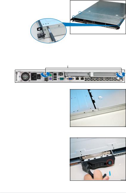
2.Loosen the two thumbscrews on the rear panel to release the rear cover from the chassis.
Thumbscrews
3.Firmly hold the front cover and slide it toward the front panel for about half an inch until it is disengaged from the chassis.
4.Released a drive tray by pushing the spring lock to the right. Then , firmly hold the tray level and pull all the drive trays out of the bay.
2-2 |
Chapter 2: Hardware setup |
5.Then push the front cover as arrow show.
6.Disconnect the LAN activity LED/ Locator LED cable and USB cable from the connectors under the front cover.
7.Disconnect the SATA cable and the power plug from the connectors on the back of the drive.
8.Leave the front cover aside.
ASUS RS160-E5 |
2-3 |
2.1.2Removing the rear cover
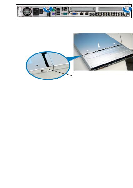
1.Loosen the two thumbscrews on the rear panel to release the top cover from the chassis.
Thumbscrews
2.Firmly hold the cover and slide it toward the rear panel for about half an inch until it is disengaged from the chassis.
1/2 inch distance
3.Lift the cover from the chassis.
2-4 |
Chapter 2: Hardware setup |
2.1.3Installing the top cover
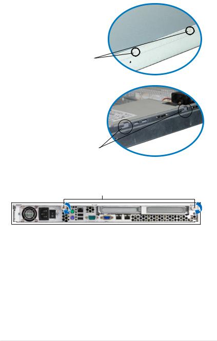
1.Position the cover on top of the chassis with the thumbscrews on the rear, and leaving a gap of about half an inch from the front panel.
Side markings
2.Make sure that the side markings on the cover (two on each side) are aligned to the grooves on the chassis.
Grooves
3.Slide the cover toward the front until it snaps in place.
4.Tighten the thumbscrews on the rear to secure the cover.
Thumbscrews
ASUS RS160-E5 |
2-5 |
2.2Central Processing Unit (CPU)
The motherboard comes with a surface mount LGA771 socket designed for the Intel® Xeon® Dual/Quad Core processor.
•Your boxed Intel® Xeon® LGA771 processor package should come with
installation instructions for the CPU and heatsink. If the instructions in this section do not match the CPU documentation, follow the latter.
•Upon purchase of the motherboard, make sure that the PnP cap is on the socket and the socket contacts are not bent. Contact your retailer
immediately if the PnP cap is missing, or if you see any damage to the PnP cap/socket contacts/motherboard components. ASUS will shoulder the cost of repair only if the damage is shipment/transit-related.
•Keep the cap after installing the motherboard. ASUS will process Return
Merchandise Authorization (RMA) requests only if the motherboard comes with the cap on the LGA771 socket.
•The product warranty does not cover damage to the socket contacts resulting from incorrect CPU installation/removal, or misplacement/loss/ incorrect removal of the PnP cap.
•If you install only one CPU, install the CPU to the CPU2 socket only. The system will not boot and the CPU warning LED will light up if a single CPU is installed on the CPU1 socket.
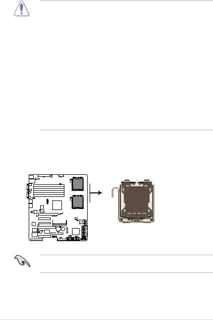
2.2.1Installing the CPU
To install a CPU:
1.Locate the CPU socket on the motherboard.
DSAN-DX
CPU1

CPU2

DSAN-DX CPU LGA771
Before installing the CPU, make sure that the socket box is facing towards you and the load lever is on your left.
2-6 |
Chapter 2: Hardware setup |
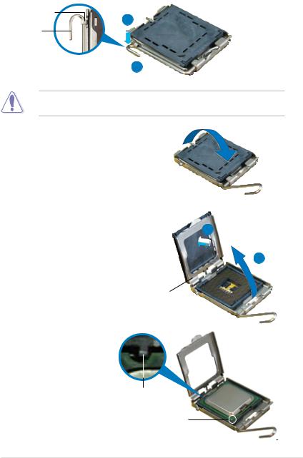
2.Press the load lever with your thumb (A), then move it to the left (B) until it is released from the retention tab.
Retention tab
A
Load lever
|
|
|
PnP cap |
B |
|
||
|
|
||
|
|
||
This side of the socket |
|||
|
|
box should face you. |
|
To prevent damage to the socket pins, do not remove the PnP cap unless you are installing a CPU.
3.Lift the load lever in the direction of the arrow to a 135º angle.
4.Lift the load plate with your thumb and forefinger to a 100º angle (A), then push the PnP cap from the load plate window to remove (B).
B
A
Load plate
5.Position the CPU over the socket, making sure that the gold triangle is on the bottom-left corner of the socket. The socket alignment key should fit into the CPU notch.
Alignment key
Gold triangle mark
ASUS RS160-E5 |
2-7 |
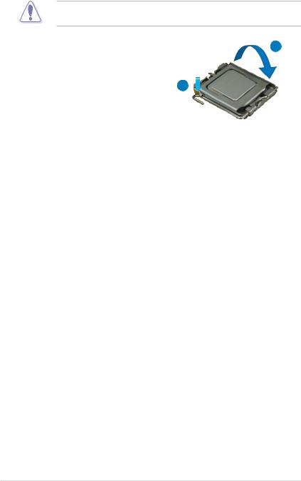
The CPU fits in only one correct orientation. DO NOT force the CPU into the socket to prevent bending the connectors on the socket and damaging the CPU!
A
6. Close the load plate (A), then push the load lever (B) until it snaps into the retention tab.
B
2-8 |
Chapter 2: Hardware setup |

2.2.2Installing the CPU heatsink and airduct
To install the CPU heatsink:
1.Carefully place the heatsink on top of the installed CPU.
2.Twist each of the four screws with a Philips (cross) screwdriver just enough to attach the heatsink to the motherboard. When the four screws are attached, tighten them one by one to completely secure the heatsink.
To install the airduct:
1.Position the airduct on top of the heatsink.
2.Carefully lower the airduct until it fits in place.
ASUS RS160-E5 |
2-9 |
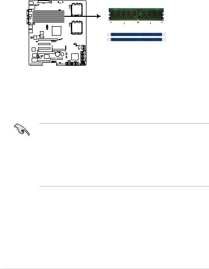
2.3System memory
2.3.1Overview
The motherboard comes with six (6) Double Data Rate 2 (DDR2) Dual Inline
Memory Modules (DIMM) sockets.
A DDR2 module has the same physical dimensions as a DDR DIMM but has a 240-pin footprint compared to the 184-pin DDR DIMM.
The figure illustrates the location of the DDR2 DIMM sockets:`
DSAN-DX
|
|
|
|
|
|
|
|
|
|
|
|
|
|
|
|
|
|
|
|
|
|
|
|
|
|
|
|
128 pins |
112 pins |
|
|
|
|
|
|
DIMM_B1
DIMM_A1
 DIMM_B2
 DIMM_A2
 DIMM_B3
 DIMM_A3
DSAN-DX 240-pin DDR2 DIMM sockets
2.3.2Memory configurations
You may install 512 MB, 1 GB, 2 GB, and 4 GB registered ECC DIMMs into the
DIMM sockets.
•For optimum compatibility, we recommend that you obtain memory modules from the same vendor. Refer to the Qualified Vendors List on the ASUS web site.
•This motherboard does not support memory modules made up of 128 Mb chips x16 memory modules.
•If you are installing only one memory module, install the module into the blue socket labeled DIMM_A1 or DIMM_B1. Installing into any other socket will not work.
2-10 |
Chapter 2: Hardware setup |
Rank population
A3 DIMM |
B3 DIMM |
A2 DIMM |
B2 DIMM |
A1 DIMM |
B1 DIMM |
MCH
DIMM installation reference table
No. of |
Slot/s to use |
DIMMs |
|
1 |
DIMM_B1 or DIMM_A1 |
2 |
DIMM_B1, DIMM_A1 |
4 |
DIMM_B1, DIMM_A1, DIMM_B2, DIMM_A2 |
6 |
DIMM_B1, DIMM_A1, DIMM_B2, DIMM_A2 |
|
DIMM_B3, DIMM_A3 |
• DIMMs in pair means two DIMMs with the same configuration.
• For better performance, same configuration DIMMs should be installed on the same slot number for each channel. For example, you may install the same type of DIMMs in DIMM_B1, and DIMM_A1.
ASUS RS160-E5 |
2-11 |
2.3.3Memory mirroring and sparing technology
The Intel® 5100MCH chipset supports the memory sparing technology. Refer to the below section:
Memory Sparing
At configuration time, a DIMM rank is set aside to replace a defective DIMM rank. When the error rate for a failing DIMM rank reaches a pre-determined threshold, the memory sparing function will issue an interrupt and initiate a spare copy. At the completion of the copy, the failing DIMM rank is disabled and the “spared” DIMM rank will be used in its place. Refer to section 5.4.3 Chipset and configure the options of Channel Rank Sparing or Channel 1 Rank Sparing to enable the memory sparing functions. The default BIOS setting is disabled.
• Each channel contains its own sparing engine and can be enabled or disabled separately.
•This motherboard does not support rank sparing across channels.
•The DIMM rank with the largest size will be assigned as spare rank. Data can only be copied from a smaller sized rank to a larger sized one.
•A DIMM can contain only one or two ranks. To support sparing function, a DIMM channel should contain at least two ranks.
•When sparing function is enabled, the usable memory size will reduce the size of the spare ranks.
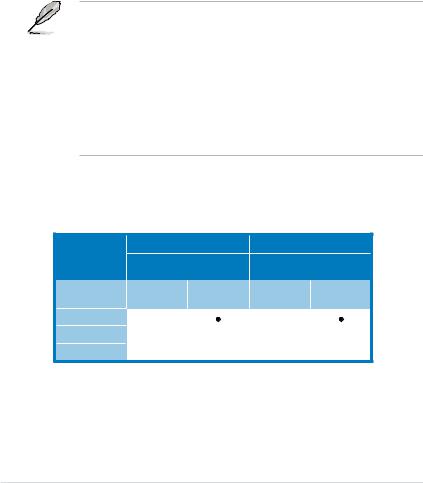
The following tables show memory configurations with Memory Sparing function in Channel A/B.
One DIMM per channel (two ranks)
Sparing
Memory space
Total Memory
Channel B |
Channel A |
||
DIMM_B1 |
DIMM_A1 |
||
(1024MB*2 Ranks) |
(1024MB*2 Ranks) |
||
Rank 0 |
Rank 1 |
Rank 0 |
Rank 1 |
(1024 MB) |
(1024 MB) |
(1024 MB) |
(1024 MB) |
|
|
|
|
1024 MB |
|
1024 MB |
|
|
2048 MB |
|
|
2-12 |
Chapter 2: Hardware setup |
Loading...