


Rampage III
GENE
Motherboard

E5934
Second Edition
July 2010
Copyright © 2010 ASUSTeK COMPUTER INC. All Rights Reserved.
No part of this manual, including the products and software described in it, may be reproduced, transmitted, transcribed, stored in a retrieval system, or translated into any language in any form or by any means, except documentation kept by the purchaser for backup purposes, without the express written permission of ASUSTeK COMPUTER INC. (“ASUS”).
Product warranty or service will not be extended if: (1) the product is repaired, modified or altered, unless such repair, modification of alteration is authorized in writing by ASUS; or (2) the serial number of the product is defaced or missing.
ASUS PROVIDES THIS MANUAL “AS IS” WITHOUT WARRANTY OF ANY KIND, EITHER EXPRESS OR IMPLIED, INCLUDING BUT NOT LIMITED TO THE IMPLIED WARRANTIES OR CONDITIONS OF MERCHANTABILITY OR FITNESS FOR A PARTICULAR PURPOSE. IN NO EVENT SHALL ASUS, ITS DIRECTORS, OFFICERS, EMPLOYEES OR AGENTS BE LIABLE FOR ANY INDIRECT, SPECIAL, INCIDENTAL, OR CONSEQUENTIAL DAMAGES (INCLUDING DAMAGES FOR LOSS OF PROFITS, LOSS OF BUSINESS, LOSS OF USE OR DATA, INTERRUPTION OF BUSINESS AND THE LIKE), EVEN IF ASUS HAS BEEN ADVISED OF THE POSSIBILITY OF SUCH DAMAGES ARISING FROM ANY DEFECT OR ERROR IN THIS MANUAL OR PRODUCT.
SPECIFICATIONS AND INFORMATION CONTAINED IN THIS MANUAL ARE FURNISHED FOR INFORMATIONAL USE ONLY, AND ARE SUBJECT TO CHANGE AT ANY TIME WITHOUT NOTICE, AND SHOULD NOT BE CONSTRUED AS A COMMITMENT BY ASUS. ASUS ASSUMES NO RESPONSIBILITY OR LIABILITY FOR ANY ERRORS OR INACCURACIES THAT MAY APPEAR IN THIS MANUAL, INCLUDING THE PRODUCTS AND SOFTWARE DESCRIBED IN IT.
Products and corporate names appearing in this manual may or may not be registered trademarks or copyrights of their respective companies, and are used only for identification or explanation and to the owners’ benefit, without intent to infringe.
ii

Contents
Notices....................................................................................................... |
viii |
Safety information....................................................................................... |
ix |
About this guide........................................................................................... |
x |
Rampage III GENE specifications summary............................................ |
xii |
Chapter 1: |
Product introduction |
|
|
1.1 |
Welcome!....................................................................................... |
1-1 |
|
1.2 |
Package contents......................................................................... |
1-1 |
|
1.3 |
Special features............................................................................ |
1-2 |
|
|
1.3.1 |
Product highlights............................................................ |
1-2 |
|
1.3.2 |
ROG Intelligent Performance & Overclocking features... |
1-3 |
|
1.3.3 |
ROG unique features....................................................... |
1-4 |
|
1.3.4 |
ASUS special features..................................................... |
1-5 |
Chapter 2: |
Hardware information |
|
|
2.1 |
Before you proceed...................................................................... |
2-1 |
|
2.2 |
Motherboard overview................................................................. |
2-7 |
|
|
2.2.1 |
Motherboard layout.......................................................... |
2-7 |
|
2.2.2 |
Layout contents............................................................... |
2-8 |
|
2.2.3 |
Placement direction......................................................... |
2-9 |
|
2.2.4 |
Screw holes..................................................................... |
2-9 |
2.3 |
Central Processing Unit (CPU).................................................. |
2-10 |
|
|
2.3.1 |
Installing the CPU.......................................................... |
2-10 |
|
2.3.2 |
Installing the CPU heatsink and fan.............................. |
2-13 |
|
2.3.3 |
Uninstalling the CPU heatsink and fan.......................... |
2-14 |
2.4 |
System memory.......................................................................... |
2-15 |
|
|
2.4.1 |
Overview........................................................................ |
2-15 |
|
2.4.2 |
Memory configurations.................................................. |
2-16 |
|
2.4.3 |
Installing a DIMM........................................................... |
2-22 |
|
2.4.4 |
Removing a DIMM......................................................... |
2-22 |
2.5 |
Expansion slots.......................................................................... |
2-23 |
|
|
2.5.1 |
Installing an expansion card.......................................... |
2-23 |
|
2.5.2 |
Configuring an expansion card...................................... |
2-23 |
|
2.5.3 |
Interrupt assignments.................................................... |
2-24 |
|
2.5.4 |
PCI slot.......................................................................... |
2-25 |
iii

Contents
|
2.5.5 |
PCI Express x4 slot . ...................................................... |
2-25 |
|
2.5.6 |
PCI Express 2.0 x16 slots ............................................. |
2-25 |
2.6 |
Jumper |
......................................................................................... |
2-27 |
2.7 |
Connectors.................................................................................. |
2-29 |
|
|
2.7.1 .................................................. |
Rear panel connectors |
2-29 |
|
2.7.2 ................................................... |
Audio I/O connections |
2-30 |
|
2.7.2 ........................................................ |
Internal connectors |
2-33 |
|
2.7.3 .......................................................... |
Onboard switches |
2-43 |
|
2.7.4 ........................................................................... |
ProbeIt |
2-45 |
2.8 |
Starting ......................................................up for the first time |
2-46 |
|
2.9 |
Turning ...........................................................off the computer |
2-47 |
|
|
2.9.1 .................................. |
Using the OS shut down function |
2-47 |
|
2.9.2 ............................ |
Using the dual function power switch |
2-47 |
Chapter 3: |
BIOS setup |
|
|
3.1 |
Managing and updating your BIOS............................................. |
3-1 |
|
|
3.1.1 |
ASUS Update utility......................................................... |
3-1 |
|
3.1.2 |
ASUS EZ Flash 2 utility................................................... |
3-4 |
|
3.1.3 |
ASUS CrashFree BIOS 3 utility....................................... |
3-5 |
3.2 |
BIOS setup program..................................................................... |
3-6 |
|
|
3.2.1 |
BIOS menu screen.......................................................... |
3-7 |
|
3.2.2 |
Menu bar......................................................................... |
3-7 |
|
3.2.3 |
Navigation keys............................................................... |
3-7 |
|
3.2.4 |
Menu items...................................................................... |
3-8 |
|
3.2.5 |
Submenu items................................................................ |
3-8 |
|
3.2.6 |
Configuration fields.......................................................... |
3-8 |
|
3.2.7 |
Pop-up window................................................................ |
3-8 |
|
3.2.8 |
Scroll bar......................................................................... |
3-8 |
|
3.2.9 |
General help.................................................................... |
3-8 |
3.3 |
Extreme Tweaker menu................................................................ |
3-9 |
|
|
3.3.1 |
Tuning Mode [Extreme OC]........................................... |
3-10 |
|
3.3.2 |
CPU Level Up [Auto]..................................................... |
3-10 |
|
3.3.3 |
Ai Overclock Tuner [Auto].............................................. |
3-10 |
|
3.3.4 |
CPU Ratio Setting [Auto]................................................ |
3-11 |
|
3.3.5 |
CPU Turbo Power Limit [Enabled].................................. |
3-11 |
iv

Contents
|
3.3.6 |
CPU Configuration.......................................................... |
3-11 |
|
3.3.7 |
BCLK Frequency [XXX].................................................. |
3-11 |
|
3.3.8 |
PCIE Frequency [XXX]................................................... |
3-11 |
|
3.3.9 |
DRAM Frequency [Auto]................................................. |
3-11 |
|
3.3.10 |
UCLK Frequency [Auto].................................................. |
3-11 |
|
3.3.11 |
QPI Link Data Rate [Auto]............................................. |
3-12 |
|
3.3.12 |
Memory Configuration Protect [Disabled]...................... |
3-12 |
|
3.3.13 |
DRAM Timing Control.................................................... |
3-12 |
|
3.3.14 |
EPU II Phase Control [Full Phase]................................ |
3-14 |
|
3.3.15 |
CPU Load-Line Calibration [Auto]................................. |
3-14 |
|
3.3.16 |
CPU Differential Amplitude [Auto].................................. |
3-14 |
|
3.3.17 |
IOH Voltage OCP [Enabled].......................................... |
3-14 |
|
3.3.18 |
DRAM Voltage OCP [Enabled]...................................... |
3-14 |
|
3.3.19 |
QPI Voltage OCP [Enabled]........................................... |
3-14 |
|
3.3.20 |
Extreme OV [Disabled].................................................. |
3-14 |
|
3.3.21 |
CPU Voltage Control [Absolute (VID)] .......................... |
3-15 |
|
3.3.22 |
CPU Voltage [Auto] ....................................................... |
3-15 |
|
3.3.23 |
CPU PLL Voltage [Auto]................................................ |
3-15 |
|
3.3.24 |
QPI/DRAM Core Voltage [Auto]..................................... |
3-15 |
|
3.3.25 |
IOH Voltage [Auto]......................................................... |
3-15 |
|
3.3.26 |
IOH PCIE Voltage [Auto]............................................... |
3-15 |
|
3.3.27 |
ICH Voltage [Auto]......................................................... |
3-15 |
|
3.3.28 |
ICH PCIE Voltage [Auto]................................................ |
3-15 |
|
3.3.29 |
DRAM Bus Voltage [Auto]............................................. |
3-16 |
|
3.3.30 |
DRAM REF Voltages..................................................... |
3-16 |
|
3.3.31 |
CPU Spread Spectrum [Auto]........................................ |
3-16 |
|
3.3.32 |
PCIE Spread Spectrum [Auto]....................................... |
3-16 |
|
3.3.33 |
CPU Clock Skew [Auto]................................................. |
3-16 |
|
3.3.34 |
IOH Clock Skew [Auto].................................................. |
3-16 |
3.4 |
Main menu................................................................................... |
3-17 |
|
|
3.4.1 |
System Time [xx:xx:xx].................................................. |
3-17 |
|
3.4.2 |
System Date [Day xx/xx/xxxx]....................................... |
3-17 |
|
3.4.3 |
Language [English]........................................................ |
3-17 |
|
3.4.4 |
SATA1–6......................................................................................... |
3-18 |

Contents
|
3.4.5 |
Storage Configuration.................................................... |
3-20 |
|
3.4.6 |
AHCI Configuration........................................................ |
3-21 |
|
3.4.7 |
System Information........................................................ |
3-22 |
3.5 |
Advanced menu.......................................................................... |
3-23 |
|
|
3.5.1 |
CPU Configuration......................................................... |
3-23 |
|
3.5.2 |
Chipset.......................................................................... |
3-26 |
|
3.5.3 |
Onboard Devices Configuration.................................... |
3-27 |
|
3.5.4 |
USB Configuration......................................................... |
3-29 |
|
3.5.5 |
PCIPnP.......................................................................... |
3-30 |
|
3.5.6 |
LED Control................................................................... |
3-31 |
|
3.5.7 |
iROG Configuration....................................................... |
3-32 |
|
3.5.8 |
ROG Connect................................................................ |
3-33 |
3.6 |
Power menu................................................................................ |
3-34 |
|
|
3.6.1 |
Suspend Mode [Auto].................................................... |
3-34 |
|
3.6.2 |
Repost Video on S3 Resume [No]................................. |
3-34 |
|
3.6.3 |
ACPI 2.0 Support [Disabled].......................................... |
3-34 |
|
3.6.4 |
ACPI APIC Support [Enabled]....................................... |
3-35 |
|
3.6.5 |
EuP Ready [Disabled].................................................... |
3-35 |
|
3.6.6 |
APM Configuration........................................................ |
3-35 |
|
3.6.7 |
Hardware Monitor.......................................................... |
3-37 |
3.7 |
Boot menu................................................................................... |
3-40 |
|
|
3.7.1 |
Boot Device Priority....................................................... |
3-40 |
|
3.7.2 |
Boot Settings Configuration........................................... |
3-41 |
|
3.7.3 |
Security.......................................................................... |
3-42 |
3.8 |
Tools menu.................................................................................. |
3-44 |
|
|
3.8.1 |
ASUS EZ Flash 2.......................................................... |
3-44 |
|
3.8.2 |
ASUS O.C. Profile......................................................... |
3-45 |
|
3.8.3 |
GO_Button File.............................................................. |
3-47 |
|
3.8.4 |
Drive Xpert Configuration.............................................. |
3-48 |
3.9 |
Exit menu..................................................................................... |
3-49 |
|
Chapter 4: |
Software support |
|
|
4.1 |
Installing an operating system.................................................... |
4-1 |
|
4.2 |
Support DVD information............................................................. |
4-1 |
|
|
4.2.1 |
Running the support DVD................................................ |
4-1 |
vi

Contents
|
4.2.2 |
Drivers menu................................................................... |
4-2 |
|
4.2.3 |
Utilities menu................................................................... |
4-3 |
|
4.2.4 |
Make disk menu.............................................................. |
4-4 |
|
4.2.5 |
Manual menu................................................................... |
4-4 |
|
4.2.6 |
Video menu...................................................................... |
4-5 |
|
4.2.7 |
ASUS Contact information............................................... |
4-5 |
|
4.2.8 |
Other information............................................................. |
4-6 |
4.3 |
Software information.................................................................... |
4-8 |
|
|
4.3.1 |
ASUS AI Suite II.............................................................. |
4-8 |
|
4.3.2 |
TurboV EVO.................................................................... |
4-9 |
|
4.3.3 |
FAN Xpert....................................................................... |
4-11 |
|
4.3.4 |
Probe II.......................................................................... |
4-12 |
|
4.3.5 |
Sensor Recorder........................................................... |
4-14 |
|
4.3.6 |
Sound Blaster X-Fi........................................................ |
4-15 |
4.4 |
RAID configurations................................................................... |
4-18 |
|
|
4.4.1 |
RAID definitions............................................................. |
4-18 |
|
4.4.2 |
Installing Serial ATA hard disks...................................... |
4-19 |
|
4.4.3 |
Setting the RAID item in BIOS....................................... |
4-19 |
|
4.4.4 |
Intel® Matrix Storage Manager option ROM utility......... |
4-20 |
4.5 |
Creating a RAID driver disk....................................................... |
4-25 |
|
|
4.5.1 |
Creating a RAID driver disk without entering the OS.... |
4-25 |
|
4.5.2 |
Creating a RAID driver disk in Windows®...................... |
4-25 |
Chapter 5: |
Multiple GPU technology support |
|
|
5.1 |
ATI® CrossFireX™ technology..................................................... |
5-1 |
|
|
5.1.1 |
Requirements.................................................................. |
5-1 |
|
5.1.2 |
Before you begin............................................................. |
5-1 |
|
5.1.3 |
Installing CrossFireX graphics cards............................... |
5-2 |
|
5.1.4 |
Installing the device drivers............................................. |
5-3 |
|
5.1.5 |
Enabling the ATI® CrossFireX™ technology.................... |
5-3 |
5.2 |
NVIDIA® SLI™ technology............................................................ |
5-5 |
|
|
5.2.1 |
Requirements.................................................................. |
5-5 |
|
5.2.2 |
Installing two SLI-ready graphics cards........................... |
5-5 |
|
5.2.3 |
Installing the device drivers............................................. |
5-6 |
|
5.2.4 |
Enabling the NVIDIA® SLI™ technology.......................... |
5-6 |
vii

Notices
Federal Communications Commission Statement
This device complies with Part 15 of the FCC Rules. Operation is subject to the following two conditions:
•This device may not cause harmful interference, and
•This device must accept any interference received including interference that may cause undesired operation.
This equipment has been tested and found to comply with the limits for a Class B digital device, pursuant to Part 15 of the FCC Rules. These limits are designed to provide reasonable protection against harmful interference in a residential installation. This equipment generates, uses and can radiate radio
frequency energy and, if not installed and used in accordance with manufacturer’s instructions, may cause harmful interference to radio communications. However, there is no guarantee that interference will not occur in a particular installation. If this equipment does cause harmful interference to radio or television reception, which can be determined by turning the equipment off and on, the user is encouraged to try to correct the interference by one or more of the following measures:
•Reorient or relocate the receiving antenna.
•Increase the separation between the equipment and receiver.
•Connect the equipment to an outlet on a circuit different from that to which the receiver is connected.
•Consult the dealer or an experienced radio/TV technician for help.
The use of shielded cables for connection of the monitor to the graphics card is required to assure compliance with FCC regulations. Changes or modifications to this unit not expressly approved by the party responsible for compliance could void the user’s authority to operate this equipment.
Canadian Department of Communications Statement
This digital apparatus does not exceed the Class B limits for radio noise emissions from digital apparatus set out in the Radio Interference Regulations of the Canadian Department of Communications.
This class B digital apparatus complies with Canadian ICES-003.
REACH
Complying with the REACH (Registration, Evaluation, Authorization, and Restriction of Chemicals) regulatory framework, we published the chemical substances in our products at ASUS website at http://green.asus.com/english/ REACH.htm.
viii

Safety information
Electrical safety
•To prevent electrical shock hazard, disconnect the power cable from the electrical outlet before relocating the system.
•When adding or removing devices to or from the system, ensure that the power cables for the devices are unplugged before the signal cables are connected. If possible, disconnect all power cables from the existing system before you add a device.
•Before connecting or removing signal cables from the motherboard, ensure that all power cables are unplugged.
•Seek professional assistance before using an adapter or extension cord. These devices could interrupt the grounding circuit.
•Ensure that your power supply is set to the correct voltage in your area. If you are not sure about the voltage of the electrical outlet you are using, contact your local power company.
•If the power supply is broken, do not try to fix it by yourself. Contact a qualified service technician or your retailer.
Operation safety
•Before installing the motherboard and adding devices on it, carefully read all the manuals that came with the package.
•Before using the product, ensure all cables are correctly connected and the power cables are not damaged. If you detect any damage, contact your dealer immediately.
•To avoid short circuits, keep paper clips, screws, and staples away from connectors, slots, sockets and circuitry.
•Avoid dust, humidity, and temperature extremes. Do not place the product in any area where it may become wet.
•Place the product on a stable surface.
•If you encounter technical problems with the product, contact a qualified service technician or your retailer.
DO NOT throw the motherboard in municipal waste. This product has been designed to enable proper reuse of parts and recycling. This symbol of the crossed out wheeled bin indicates that the product (electrical and electronic equipment) should not be placed in municipal waste. Check local regulations for disposal of electronic products.
DO NOT throw the mercury-containing button cell battery in municipal waste. This symbol of the crossed out wheeled bin indicates that the battery should not be placed in municipal waste.
ix

About this guide
This user guide contains the information you need when installing and configuring the motherboard.
How this guide is organized
This guide contains the following parts:
•Chapter 1: Product introduction
This chapter describes the features of the motherboard and the new technology it supports.
•Chapter 2: Hardware information
This chapter lists the hardware setup procedures that you have to perform when installing system components. It includes description of the switches, jumpers, and connectors on the motherboard.
•Chapter 3: BIOS setup
This chapter tells how to change system settings through the BIOS Setup menus. Detailed descriptions of the BIOS parameters are also provided.
•Chapter 4: Software support
This chapter describes the contents of the support DVD that comes with the motherboard package and the software.
•Chapter 5: Multiple GPU technology support
This chapter describes how to install and configure multiple ATI® CrossFireX™ graphics cards.
•Appendix: Debug code table
The Appendix lists the debug code table for the LCD Poster.
Where to find more information
Refer to the following sources for additional information and for product and software updates.
1.ASUS websites
The ASUS website provides updated information on ASUS hardware and software products. Refer to the ASUS contact information.
2.Optional documentation
Your product package may include optional documentation, such as warranty flyers, that may have been added by your dealer. These documents are not part of the standard package.
Conventions used in this guide
To ensure that you perform certain tasks properly, take note of the following symbols used throughout this manual.
DANGER/WARNING: Information to prevent injury to yourself when trying to complete a task.
CAUTION: Information to prevent damage to the components when trying to complete a task.
IMPORTANT: Instructions that you MUST follow to complete a task.
NOTE: Tips and additional information to help you complete a task.
Typography
Bold text |
Indicates a menu or an item to select. |
Italics |
Used to emphasize a word or a phrase. |
<Key> |
Keys enclosed in the less-than and greater-than sign |
|
means that you must press the enclosed key. |
|
Example: <Enter> means that you must press the |
|
Enter or Return key. |
<Key1+Key2+Key3> |
If you must press two or more keys simultaneously, the |
|
key names are linked with a plus sign (+). |
|
Example: <Ctrl+Alt+D> |
Command |
Means that you must type the command exactly as |
|
shown, then supply the required item or value enclosed |
|
in brackets. |
|
Example: At the DOS prompt, type the command line: |
|
afudos /iMAIIGEN.ROM |
xi

Rampage III GENE specifications summary
CPU
Chipset
System Bus
Memory
Expansion Slots
Multi-GPU Technology
Storage
LAN
High Definition Audio
IEEE 1394
USB
LGA1366 socket for Intel® Core™i7 Processor Extreme Edition / Core™i7 Processors
-Support Intel® Turbo Boost Technology
*Refer to www.asus.com for Intel CPU support list
Intel® X58/ICH10R
Up to 6.4 GT/s with QuickPath Interconnection
Triple channel memory architecture
6 x DIMM, max. 24GB, DDR3 2200(O.C.)/2133(O. C.)/2000(O.C)/1800(O.C.)/1600/1333/1066 MHz, nonECC, un-buffered memory modules
Supports Intel® Extreme Memory Profile (XMP) *Hyper DIMM support is subject to the physical
characteristics of individual CPUs.
*Refer to www.asus.com or this user manual for the
Memory QVL (Qualified Vendors Lidts)..
2 x PCIe2.0 x16 slots, support dual x16 mode
1 x PCIe x4
1 x PCI 2.2
Support NVIDIA SLI™ / ATI CrossFireX™ Technology
ICH10R Southbridge:
-6 x SATA 3.0 Gb/s ports (gray)
-Intel Matrix Storage Technology supports RAID 0, 1, 5 and 10
Marvell® PCIe 9128 SATA 6Gb/s controller
- 2 x SATA 6.0 Gb/s ports (red)
Intel® Gigabit LAN
SupremeFX X-Fi 2 built-in
-8-channel High Definition Audio CODEC
-EAX® Advanced™ HD 5.0
-THX TrueStudio PC
-X-Fi® Xtreme Fidelity™
-Creative ALchemy
-Supports Blu-ray audio layer content protection
-Supports Jack-detection, Multi-streaming, Front
Panel Jack-retasking
-Supports 1 x Optical S/PDIF out port at back panel
2 x 1394a ports (1 port at back panel, 1 port at midboard)
NEC® USB 3.0 controller
- 2 x USB 3.0/2.0 ports (at back panel)
Intel® ICH10R Southbridge
-11 x USB 2.0/1.1 ports (4 ports at midboard; 6 ports at back panel, 1 reserved for ROG Connect)
(continued on the next page)
xii

Rampage III GENE specifications summary
ROG Exclusive Features |
Power Design: |
|
- 8-phase CPU power |
|
- 2-phase QPI/DRAM power |
|
- 2-phase NB power |
|
ROG Connect |
|
ProbeIt |
|
iROG |
|
GameFirst |
|
CPU Level Up |
|
MemOK! |
|
Extreme Tweaker |
|
Q-Fan Plus (without thermal sensor cables) |
|
Loadline Calibration |
|
Intelligent Overclocking Tools: |
|
- ASUS TurboV EVO |
|
- O.C Profile |
|
Overclocking Protection: |
|
- COP EX (Component Overheat Protection - EX) |
|
- Voltiminder LED |
|
- ASUS C.P.R.(CPU Parameter Recall) |
Other Special Features |
|
ASUS MyLogo3 |
|
|
ASUS Fan Xpert |
|
ASUS EZ Flash 2 |
|
ASUS CrashFree BIOS 3 |
|
ASUS Q-Connector |
|
ASUS Q-Slot |
|
ASUS Q-DIMM |
BIOS Features |
|
16Mb AMI BIOS, PnP, DMI2.0, WfM2.0, SM BIOS 2.5, |
|
|
ACPI2.0a Multi-Language BIOS |
Manageability |
|
WOL by PME, WOR by PME, PXE |
|
Back Panel I/O Ports |
1 x PS/2 Keyboard port (purple) |
|
1 x Clr CMOS switch |
|
1 x Optical S/PDIF out port |
|
1 x IEEE 1394a connector |
|
1 x LAN (RJ45) port |
|
1 x ROG Connect On/Off switch |
|
2 x USB 3.0/2.0 ports (Blue) |
|
7 x USB 2.0/1.1 ports (1 port also for ROG Connect) |
|
8-channel Audio I/O |
|
|
|
(continued on the next page) |
xiii

Rampage III GENE specifications summary
Internal I/O Connectors |
2 x USB 2.0 connectors support additional 4 USB 2.0 |
|
ports |
|
8 x SATA connectors: 2 x SATA 6G connectors (Red); 6 x |
|
standard SATA connectors (Gray) |
|
5 x Fan connectors: 1 x CPU / 1 x PWR / 2 x Chassis / 1 |
|
x Optional |
|
8 x ProbeIt Measurement Points |
|
1 x Go Button |
|
1 x Thermal sensor connector |
|
1 x IEEE1394a connector |
|
1 x SPDIF_Out Connector |
|
1 x 24-pin ATX Power connector |
|
1 x 8-pin ATX 12V Power connectors |
|
1 x En/Dis-able Clr CMOS header |
|
1 x En/Dis-able QPI_LL header |
|
1 x START (Power On) button |
|
1 x RESET button |
|
1 x Front panel audio connector |
|
1 x System panel connector |
Software |
|
Support DVD: |
|
|
- Drivers and Applications |
|
Sound Blaster X-Fi MB2 Utility |
|
Kaspersky Anti-Virus |
|
ROG GameFirst Utility |
|
ASUS AI Suite II |
|
ASUS PC Probe II |
|
ASUS Update |
Form Factor |
|
mATX Form Factor, 9.6”x 9.6” (24.4cm x 24.4cm) |
*Specifications are subject to change without notice.
xiv
This chapter describes the motherboard |
1 |
|
|
features and the new technologies |
|
it supports. |
|
Chapter 1: Product |
|
|
introduction |

|
Chapter summary |
1 |
|
|
|
||
|
|
|
|
|
|
|
|
1.1 |
Welcome!....................................................................................... |
1-1 |
1.2 |
Package contents......................................................................... |
1-1 |
1.3 |
Special features............................................................................ |
1-2 |
ROG Rampage III GENE

1.1Welcome!
Thank you for buying an ROG Rampage III GENE motherboard!
The motherboard delivers a host of new features and latest technologies, making it another standout in the long line of ASUS quality motherboards!
Before you start installing the motherboard, and hardware devices on it, check the items in your package with the list below.
1.2Package contents
Check your motherboard package for the following items.
Motherboard |
ROG Rampage III GENE |
|
|
Cables |
1 x SLI Cable |
|
3 x 2-in-1 SATA signal cables |
|
1 x 2-in-1 SATA 6G cables |
|
|
Accessories |
1 x ROG Connect cable |
|
1 x 2 in 1 ASUS Q-Connector Kit |
|
1 x I/O Shield |
|
1 x Cable Ties Pack |
|
1 x ROG theme label |
|
1 x 12-in-1 ROG Cable Label |
|
|
Application DVD |
ROG motherboard support DVD |
|
|
Documentation |
User guide |
|
|
If any of the above items is damaged or missing, contact your retailer.
ROG Rampage III GENE |
1-1 |

1.3Special features
1.3.1Product highlights
Republic of Gamers
The Republic of Gamers consists only the best of the best. We offer the best hardware engineering, the fastest performance, the most innovating ideas, and we welcome the best gamers to join in. In the Republic of Gamers, mercy rules are only for the weak, and bragging rights means everything. We believe in making statements and we excel in competitions. If your character matches our trait, then join the elite club, make your presence felt, in the Republic of Gamers.
Green ASUS
This motherboard and its packaging comply with the European Union’s Restriction on the use of Hazardous Substances (RoHS). This is in line with the ASUS vision of creating environment-friendly and recyclable products/packaging to safeguard consumers’ health while minimizing the impact on the environment.
LGA1366 Intel® Core™ i7 Ready 
This motherboard supports the latest Intel® Core™ i7 processors in LGA1366 package with integrated memory controller to support 3-channel (6 DIMMs) DDR3 memory. Supports Intel® QuickPath Interconnect (QPI) with a system bus of up to 6.4 GT/s and a max bandwidth of up to 25.6 GB/s. Intel® Core™ i7 processor is one of the most powerful and energy efficient CPUs in the world.
Intel® X58 Chipset 
The Intel® X58 Express Chipset is one of the most powerful chipset designed to support the Intel® Core™ i7 Processors with LGA1366 package and Intel® next generation system interconnect interface, Intel® QuickPath Interconnect (QPI), providing improved performance by utilizing serial point-to-point links, allowing increased bandwidth and stability. It also supports up to 36 PCI Express 2.0 lanes providing better graphics performance.
SLI/CrossFireX On-Demand 
Why choose when you can have both?
SLI or CrossFireX? Fret no longer because with the ROG Rampage III GENE, you'll be able to run both multi-GPU setups. The board features SLI/CrossFireX on Demand technology, supporting SLI or CrossFireX configuration. Whichever path you take, you can be assured of jaw-dropping graphics at a level previously unseen.
1-2 |
Chapter 1: Product Introduction |

Tri-Channel, DDR3 2200(O.C.) MHz 
The motherboard supports DDR3 memory that features data transfer rates of 2200(O.C.)/2133(O.C.)/2000(O.C.)/1800(O.C.)/1600/1333/1066 MHz to meet the higher bandwidth requirements of the latest operation system, 3D graphics,
multimedia, and Internet applications. The dual-channel DDR3 architecture double the bandwidth of your system memory to boost system performance.
PCIe 2.0 
Double Speed; Double Bandwidth
This motherboard supports the latest PCIe 2.0 devices for double speed and bandwidth which enhances system performance.
1.3.2ROG Intelligent Performance & Overclocking features
ROG Connect 
Plug and Overclock - Tweak it the hardcore way!
Monitor the status of your desktop PC and tweak its parameters in real-time via a notebook—just like a race car engineer—with ROG Connect. ROG Connect links your main system to a notebook through a USB cable, allowing you to view realtime POST code and hardware status readouts on your notebook, as well as make on-the-fly parameter adjustments at a purely hardware level. Diagram, power, reset
button, flash BIOS through notebook. Refer to page 2-32 for details.
MemOK! 
Any memory is A-OK!
Memory compatibility is among the top concerns when it comes to computer upgrades. Worry no more, MemOK! is the fastest memory booting solution today. This remarkable memory rescue tool requires nothing but a push of a button
to patch memory issues and get your system up and running in no time. The technology is able to determine failsafe settings that can dramatically improve system booting success.
iROG 
Intelligent multiple control at hand
The iROG is a special IC which enables several ROG highlighted functions that gives users full disposal of the motherboard at any stage! This design allows advanced user control and management to be processed purely at a hardware level. iROG greatly increases fun during overclocking for PC enthusiasts and it offers system maintenance and management with more control and efficiency.
ROG Rampage III GENE |
1-3 |

ProbeIt 
Get all hands-on with hardware-based overclocking
ProbeIt takes the guesswork out of locating the motherboard’s measurement points, identifying them clearly in the form of 8 sets of detection points so you’ll know exactly where to get quick yet accurate readings using a multitester.
CPU Level Up 
A simple click for instant upgrade!
Ever wish that you could have a more expansive CPU? Upgrade your CPU at no additional cost with ROG's CPU Level Up! Simply pick the processor you wanted to OC to, and the motherboard will do the rest! See the new CPU speed and enjoy that performance instantly. Overclocking is never as easy as this.
Extreme Tweaker 
One stop performance tuning shop
Extreme Tweakers is the one stop shop to fine-tune your system to optimal performance. No matter if you're looking for frequency adjustment, over-voltage options, or memory timing settings, they're all here!
Voltiminder LED 
Friendly reminder on Voltage Settings
In the pursuit of extreme performance, overvoltage adjustment is critical but risky. Acting as the "red zone" of a tachometer, the Voltiminder LED displays the voltage status for CPU, PCH, and Memory in a intuitive color-coded fashion. The voltiminder LED allows quick voltage monitoring for overclockers.
1.3.3ROG unique features
COP EX 
Maximum OC with confidence with burn proof protection to chipsets and
CPU!
The COP EX allows overclockers to increase chipset voltage without the worries of overheating. It can also be used to monitor and save an overheating CPU. The COP EX allows more freedom and less constraint for maximum performance achievement.
1-4 |
Chapter 1: Product Introduction |
Loadline Calibration 
Optimal power boost for extreme CPU overclocking!
Maintaining ample voltage support for the CPU is critical during overclocking. The Loadline Calibration ensures stable and optimal CPU voltage under heavy
loading. It helps overclockers enjoy the motherboard's ultimate OC capabilities and benchmark scores.
Onboard Switches 
No more shorting pins or moving jumpers
With an easy press during overclock, this exclusive onboard switch allows gamer to effortlessly fine-tune the performance without having to short the pins or moving jumpers!
ASUS Q-Connector 
Make connections quick and accurate
The Q-Connector allows you to connect or disconnect chassis front panel cables in one easy step with one complete module. This unique adapter eliminates the trouble of plugging in one cable at a time, making connection quick and accurate.
1.3.4ASUS special features
USB 3.0 Support 
10X Faster Date Rates!
Experience ultra-fast data transfers at 4.8Gbps with USB 3.0—the latest connectivity standard. Built to connect easily with next generation components and peripherals, USB 3.0 transfers data 10X faster and is also backward compatible with USB 2.0 components.
SATA 6Gb/s Support 
Experience the Future of Storage!
Supporting next-generation Serial ATA (SATA) storage interface, this motherboard delivers up to 6.0Gb/s data transfer rates. Additionally, get enhanced scalability, faster data retrieval, double the bandwidth of current bus systems.
ROG Rampage III GENE |
1-5 |

O.C. Profile 
Conveniently store or load multiple BIOS settings
Freely share and distribute favorite overclocking settings The motherboard features the ASUS O.C. Profile that allows users to conveniently store or load multiple BIOS settings. The BIOS settings can be stored in the CMOS or a separate file, giving users freedom to share and distribute their favorite overclocking settings.
8-channel Audio 
Enjoy High-End 8-channel sound system on your PC
The onboard 8-channel HD audio (High Definition Audio, previously code-named Azalia) CODEC enables high-quality 192KHz/24-bit audio output, jack-sensing feature, retasking functions and multi-streaming technology that simultaneously sends different audio streams to different destinations. This motherboard now adopts the future standard to deliver the most vivid audio enjoyment.
Kaspersky® Anti-Virus 
The best protection from viruses and spyware
Kaspersky® Anti-Virus Personal offers premium antivirus protection for individual users and home offices. It is based on advanced antivirus technologies. The product incorporates the Kaspersky® Anti-Virus engine, which is renowned for malicious program detection rates that are among the industry's highest.
1-6 |
Chapter 1: Product Introduction |
This chapter lists the hardware setup procedures that you have to perform when installing system components. It Chapterincludes description of the jumpers2:and connectors on the motherboard.
Hardware2 information

|
Chapter summary |
2 |
|
|
|
||
|
|
|
|
|
|
|
|
2.1 |
Before you proceed...................................................................... |
2-1 |
2.2 |
Motherboard overview................................................................. |
2-7 |
2.3 |
Central Processing Unit (CPU).................................................. |
2-10 |
2.4 |
System memory.......................................................................... |
2-15 |
2.5 |
Expansion slots.......................................................................... |
2-23 |
2.6 |
Jumper......................................................................................... |
2-27 |
2.7 |
Connectors.................................................................................. |
2-29 |
2.8 |
Starting up for the first time...................................................... |
2-46 |
2.9 |
Turning off the computer........................................................... |
2-47 |
ROG Rampage III GENE

2.1Before you proceed
Take note of the following precautions before you install motherboard components or change any motherboard settings.
•Unplug the power cord from the wall socket before touching any component.
•Use a grounded wrist strap or touch a safely grounded object or a metal object, such as the power supply case, before handling components to avoid damaging them due to static electricity.
•Hold components by the edges to avoid touching the ICs on them.
•Whenever you uninstall any component, place it on a grounded antistatic pad or in the bag that came with the component.
•Before you install or remove any component, ensure that the ATX power supply is switched off or the power cord is detached from the power supply. Failure to do so may cause severe damage to the motherboard, peripherals, and/or components.
ROG Rampage III GENE |
2-1 |
Onboard LEDs
The motherboard comes with LEDs that indicate the voltage conditions of CPU, memory, northbridge, and southbridge. You may adjust the voltages in BIOS. There
are also an LED for hard disk drive activity and an onboard switch for power status. For more information about voltage adjustment, refer to 3.3 Extreme Tweaker menu.
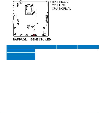
1.CPU LED
The CPU LED has three voltage displays: Vcore voltage, CPU PLL 1.8 voltage, and QPI/DRAM Core voltage you can select the voltage to display in BIOS. Refer to the illustration below for the location of the CPU LED and the table below for LED definition.
|
|
|
|
|
|
|
|
|
|
|
|
|
|
|
|
|
|
|
|
|
|
|
|
|
|
|
|
|
|
|
|
|
|
|
|
|
|
|
|
|
|
|
|
|
|
|
|
|
|
|
|
|
|
|
|
|
|
|
|
|
|
|
|
|
|
|
|
|
|
|
|
|
|
|
|
|
|
|
|
|
|
|
|
|
|
|
|
|
|
|
|
|
|
|
|
|
|
|
|
|
|
|
|
|
|
|
|
|
|
|
|
|
|
|
|
|
|
|
|
|
|
|
|
|
|
|
|
|
|
|
|
|
|
|
|
|
|
|
|
|
|
|
|
|
|
|
|
|
|
|
|
|
|
|
|
|
|
|
|
|
|
|
|
|
|
|
|
|
|
|
|
|
|
|
|
|
|
|
|
|
|
|
|
|
|
|
|
|
|
|
|
|
|
|
|
|
|
|
|
|
|
|
|
|
|
|
|
|
|
|
|
|
|
|
|
|
|
|
|
|
|
|
|
|
|
|
|
|
|
|
|
|
|
|
|
|
|
|
|
|
|
|
|
|
|
|
|
|
|
|
|
|
|
|
|
|
|
|
|
|
|
|
|
|
|
|
|
|
|
|
|
|
|
|
|
|
|
|
|
|
|
|
|
|
|
|
|
|
|
|
|
|
|
|
|
|
|
|
|
|
|
|
|
|
|
|
|
|
|
|
|
|
|
|
|
|
|
|
|
|
|
|
|
|
|
|
|
|
|
|
|
|
|
|
|
|
|
|
|
|
|
|
|
|
|
|
|
|
|
|
|
|
|
|
|
|
|
|
|
|
|
|
|
|
|
|
|
|
|
|
|
|
|
|
|
|
|
|
|
|
|
|
|
|
|
|
|
|
|
|
|
|
|
|
|
|
|
|
|
|
|
|
|
|
|
|
|
|
|
|
|
|
|
|
|
|
|
|
|
|
|
|
|
|
|
|
|
|
|
|
|
|
|
|
|
|
|
|
|
|
|
|
|
|
|
|
|
|
|
|
|
|
|
|
|
|
|
|
|
|
|
|
|
|
|
|
|
|
|
|
|
|
|
|
|
|
|
|
|
|
|
|
|
|
|
|
|
|
|
|
|
|
|
|
|
|
|
|
|
|
|
|
|
|
|
|
|
|
|
|
|
|
|
|
|
|
|
|
|
|
|
|
|
|
|
|
|
|
|
|
|
|
|
|
|
|
|
|
|
|
|
|
|
|
|
|
|
|
|
|
|
|
|
|
|
|
|
|
|
|
|
|
|
|
|
|
|
|
|
|
|
|
|
|
|
|
|
|
|
|
|
|
|
|
|
|
|
|
|
|
|
|
|
|
|
|
|
|
|
|
|
|
|
|
|
|
|
|
|
|
|
|
|
|
|
|
|
|
|
|
|
|
|
|
|
|
|
|
|
|
|
|
|
|
|
|
|
|
|
|
|
|
|
|
|
|
|
|
|
|
|
|
|
|
|
|
|
|
|
|
|
|
VCore |
|
Normal (green) |
High (yellow) |
Crazy (red) |
||||||||||||||||||||||||||||||||||||||||||||||
|
0.85–1.5 |
1.50625–1.59375 |
1.6– |
|||||||||||||||||||||||||||||||||||||||||||||||
CPU PLL 1.8V |
|
1.20375–1.89475 |
1.90800–1.94775 |
1.961– |
||||||||||||||||||||||||||||||||||||||||||||||
QPI/DRAM Core |
|
1.2–1.39375 |
1.4–1.69375 |
1.7– |
||||||||||||||||||||||||||||||||||||||||||||||
2-2 |
Chapter 2: Hardware information |
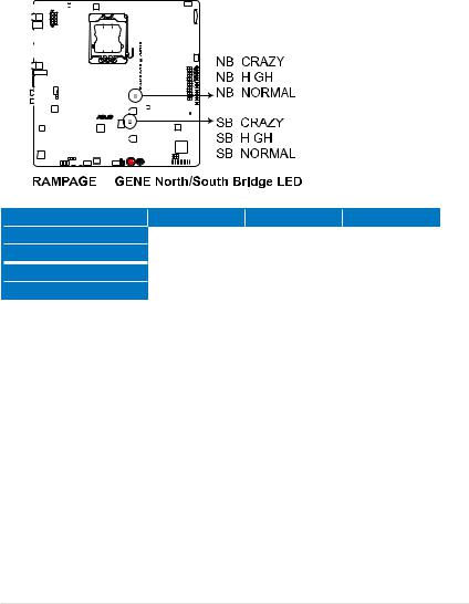
2.Northbridge/Southbridge LEDs
The northbridge and southbridge LEDs each have two different voltage displays. The northbridge LED displays either the NB 1.1 Voltage or the NB 1.5 Voltage. The southbridge LED shows either the SB 1.1 Voltage or the SB 1.5 Voltage. You can select the voltage to display in BIOS. Refer to the illustration below for the location of the northbridge/southbridge LEDs and the table below for LED definition.
|
|
|
|
|
|
|
|
|
|
|
|
|
|
|
|
|
|
|
|
|
|
|
|
|
|
|
|
|
|
|
|
|
|
|
|
|
|
|
|
|
|
|
|
|
|
|
|
|
|
|
|
|
|
|
|
|
|
|
|
|
|
|
|
|
|
|
|
|
|
|
|
|
|
|
|
|
|
|
|
|
|
|
|
|
|
|
|
|
|
|
|
|
|
|
|
|
|
|
|
|
|
|
|
|
|
|
|
|
|
|
|
|
|
|
|
|
|
|
|
|
|
|
|
|
|
|
|
|
|
|
|
|
|
|
|
|
|
|
|
|
|
|
|
|
|
|
|
|
|
|
|
|
|
|
|
|
|
|
|
|
|
|
|
|
|
|
|
|
|
|
|
|
|
|
|
|
|
|
|
|
|
|
|
|
|
|
|
|
|
|
|
|
|
|
|
|
|
|
|
|
|
|
|
|
|
|
|
|
|
|
|
|
|
|
|
|
|
|
|
|
|
|
|
|
|
|
|
|
|
|
|
|
|
|
|
|
|
|
|
|
|
|
|
|
|
|
|
|
|
|
|
|
|
|
|
|
|
|
|
|
|
|
|
|
|
|
|
|
|
|
|
|
|
|
|
|
|
|
|
|
|
|
|
|
|
|
|
|
|
|
|
|
|
|
|
|
|
|
|
|
|
|
|
|
|
|
|
|
|
|
|
|
|
|
|
|
|
|
|
|
|
|
|
|
|
|
|
|
|
|
|
|
|
|
|
|
|
|
|
|
|
|
|
|
|
|
|
|
|
|
|
|
|
|
|
|
|
|
|
|
|
|
|
|
|
|
|
|
|
|
|
|
|
|
|
|
|
|
|
|
|
|
|
|
|
|
|
|
|
|
|
|
|
|
|
|
|
|
|
|
|
|
|
|
|
|
|
|
|
|
|
|
|
|
|
|
|
|
|
|
|
|
|
|
|
|
|
|
|
|
|
|
|
|
|
|
|
|
|
|
|
|
|
|
|
|
|
|
|
|
|
|
|
|
|
|
|
|
|
|
|
|
|
|
|
|
|
|
|
|
|
|
|
|
|
|
|
|
|
|
|
|
|
|
|
|
|
|
|
|
|
|
|
|
|
|
|
|
|
|
|
|
|
|
|
|
|
|
|
|
|
|
|
|
|
|
|
|
|
|
|
|
|
|
|
|
|
|
|
|
|
|
|
|
|
|
|
|
|
|
|
|
|
|
|
|
|
|
|
|
|
|
|
|
|
|
|
|
|
|
|
|
|
|
|
|
|
|
|
|
|
|
|
|
|
|
|
|
|
|
|
|
|
|
|
|
|
|
|
|
|
|
|
|
|
|
|
|
|
|
|
|
|
|
|
|
|
|
|
|
|
|
|
|
|
|
|
|
|
|
|
|
|
NB 1.1 Voltage |
Normal (green) |
High (yellow) |
Crazy (red) |
||||||||||||||||||||||||||||||||||||||||||||
1.113–1.391 |
1.4045–1.643 |
1.65625– |
|||||||||||||||||||||||||||||||||||||||||||||
NB 1.5 Voltage |
1.5105–1.696 |
1.709–1.84175 |
1.855– |
||||||||||||||||||||||||||||||||||||||||||||
SB 1.1 Voltage |
1.113–1.591 |
1.60325–1.84175 |
1.855– |
||||||||||||||||||||||||||||||||||||||||||||
SB 1.5 Voltage |
1.5105–1.6165 |
1.62975–1.802 |
1.81525– |
||||||||||||||||||||||||||||||||||||||||||||
ROG Rampage III GENE |
2-3 |

3.Memory LED
Refer to the illustration below for the location of the memory LED and the table below for LED definition.
|
|
|
|
|
|
|
|
|
|
|
|
|
|
|
|
|
|
|
|
|
|
|
|
|
|
|
|
|
|
|
|
|
|
|
|
|
|
|
|
|
|
|
|
|
|
|
|
|
|
|
|
|
|
|
|
|
|
|
|
|
|
|
|
|
|
|
|
|
|
|
|
|
|
|
|
|
|
|
|
|
|
|
|
|
|
|
|
|
|
|
|
|
|
|
|
|
|
|
|
|
|
|
|
|
|
|
|
|
|
|
|
|
|
|
|
|
|
|
|
|
|
|
|
|
|
|
|
|
|
|
|
|
|
|
|
|
|
|
|
|
|
|
|
|
|
|
|
|
|
|
|
|
|
|
|
|
|
|
|
|
|
|
|
|
|
|
|
|
|
|
|
|
|
|
|
|
|
|
|
|
|
|
|
|
|
|
|
|
|
|
|
|
|
|
|
|
|
|
|
|
|
|
|
|
|
|
|
|
|
|
|
|
|
|
|
|
|
|
|
|
|
|
|
|
|
|
|
|
|
|
|
|
|
|
|
|
|
|
|
|
|
|
|
|
|
|
|
|
|
|
|
|
|
|
|
|
|
|
|
|
|
|
|
|
|
|
|
|
|
|
|
|
|
|
|
|
|
|
|
|
|
|
|
|
|
|
|
|
|
|
|
|
|
|
|
|
|
|
|
|
|
|
|
|
|
|
|
|
|
|
|
|
|
|
|
|
|
|
|
|
|
|
|
|
|
|
|
|
|
|
|
|
|
|
|
|
|
|
|
|
|
|
|
|
|
|
|
|
|
|
|
|
|
|
|
|
|
|
|
|
|
|
|
|
|
|
|
|
|
|
|
|
|
|
|
|
|
|
|
|
|
|
|
|
|
|
|
|
|
|
|
|
|
|
|
|
|
|
|
|
|
|
|
|
|
|
|
|
|
|
|
|
|
|
|
|
|
|
|
|
|
|
|
|
|
|
|
|
|
|
|
|
|
|
|
|
|
|
|
|
|
|
|
|
|
|
|
|
|
|
|
|
|
|
|
|
|
|
|
|
|
|
|
|
|
|
|
|
|
|
|
|
|
|
|
|
|
|
|
|
|
|
|
|
|
|
|
|
|
|
|
|
|
|
|
|
|
|
|
|
|
|
|
|
|
|
|
|
|
|
|
|
|
|
|
|
|
|
|
|
|
|
|
|
|
|
|
|
|
|
|
|
|
|
|
|
|
|
|
|
|
|
|
|
|
|
|
|
|
|
|
|
|
|
|
|
|
|
|
|
|
|
|
|
|
|
|
|
|
|
|
|
|
|
|
|
|
|
|
|
|
|
|
|
|
|
|
|
|
|
|
|
|
|
|
|
|
|
|
|
|
|
|
|
|
|
|
|
|
|
|
|
|
|
|
|
|
|
|
|
|
|
|
DDR3 1.5V |
|
|
|
Normal (green) |
High (yellow) |
Crazy (red) |
|||||||||||||||||||||||||||||||||||||||||||||
|
|
|
1.20575–1.60325 |
1.6165–1.802 |
1.81525– |
||||||||||||||||||||||||||||||||||||||||||||||
4.Hard Disk LED
The hard disk LED is designed to indicate the hard disk activity. It blinks when data is being written into or read from the hard disk drive. The LED does not light up when there is no hard disk drive connected to the motherboard or when the hard disk drive does not function.
|
|
|
|
|
|
|
|
|
|
|
|
|
|
|
|
|
|
|
|
|
|
|
|
|
|
|
|
|
|
|
|
|
|
|
|
|
|
|
|
|
|
|
|
|
|
|
|
|
|
|
|
|
|
|
|
|
|
|
|
|
|
|
|
|
|
|
|
|
|
|
|
|
|
|
|
|
|
|
|
|
|
|
|
|
|
|
|
|
|
|
|
|
|
|
|
|
|
|
|
|
|
|
|
|
|
|
|
|
|
|
|
|
|
|
|
|
|
|
|
|
|
|
|
|
|
|
|
|
|
|
|
|
|
|
|
|
|
|
|
|
|
|
|
|
|
|
|
|
|
|
|
|
|
|
|
|
|
|
|
|
|
|
|
|
|
|
|
|
|
|
|
|
|
|
|
|
|
|
|
|
|
|
|
|
|
|
|
|
|
|
|
|
|
|
|
|
|
|
|
|
|
|
|
|
|
|
|
|
|
|
|
|
|
|
|
|
|
|
|
|
|
|
|
|
|
|
|
|
|
|
|
|
|
|
|
|
|
|
|
|
|
|
|
|
|
|
|
|
|
|
|
|
|
|
|
|
|
|
|
|
|
|
|
|
|
|
|
|
|
|
|
|
|
|
|
|
|
|
|
|
|
|
|
|
|
|
|
|
|
|
|
|
|
|
|
|
|
|
|
|
|
|
|
|
|
|
|
|
|
|
|
|
|
|
|
|
|
|
|
|
|
|
|
|
|
|
|
|
|
|
|
|
|
|
|
|
|
|
|
|
|
|
|
|
|
|
|
|
|
|
|
|
|
|
|
|
|
|
|
|
|
|
|
|
|
|
|
|
|
|
|
|
|
|
|
|
|
|
|
|
|
|
|
|
|
|
|
|
|
|
|
|
|
|
|
|
|
|
|
|
|
|
|
|
|
|
|
|
|
|
|
|
|
|
|
|
|
|
|
|
|
|
|
|
|
|
|
|
|
|
|
|
|
|
|
|
|
|
|
|
|
|
|
|
|
|
|
|
|
|
|
|
|
|
|
|
|
|
|
|
|
|
|
|
|
|
|
|
|
|
|
|
|
|
|
|
|
|
|
|
|
|
|
|
|
|
|
|
|
|
|
|
|
|
|
|
|
|
|
|
|
|
|
|
|
|
|
|
|
|
|
|
|
|
|
|
|
|
|
|
|
|
|
|
|
|
|
|
|
|
|
|
|
|
|
|
|
|
|
|
|
|
|
|
|
|
|
|
|
|
|
|
|
|
|
|
|
|
|
|
|
|
|
|
|
|
|
|
|
|
|
|
|
|
|
|
|
|
|
|
|
|
|
|
|
|
|
|
|
|
|
|
|
|
|
|
|
|
|
|
|
|
|
|
|
|
|
|
|
|
|
|
|
|
|
|
|
|
|
|
|
|
|
|
|
|
|
|
|
|
|
|
|
|
|
|
|
|
|
|
|
|
|
|
|
|
|
|
|
|
|
|
|
|
|
|
|
|
|
|
|
|
|
|
|
|
|
|
|
|
|
2-4 |
|
|
|
|
|
|
|
|
|
|
|
|
|
|
|
|
|
|
|
|
|
|
|
|
|
|
|
|
|
|
|
|
|
|
|
|
|
|
|
|
|
|
|
|
|
|
Chapter 2: Hardware information |
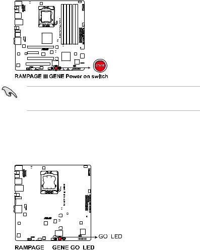
5.Power LED
The motherboard comes with a power-on switch that lights up to indicate that the system is ON, in sleep mode, or in soft off mode. This is a reminder that you should shut down the system and unplug the power cable before removing or plugging in any motherboard component. The illustration below shows the location of the onboard power-on switch.
When you turn on the ATX power supply, the Power LED flashes three times to indicate that the system is ready to boot. Wait till the flash stops before you press the power-on switch.
6.GO LED
Blinking: Indicates that MemOK! is enabled before POST.
Lighting: Indicates that the system loads the preset profile (GO_Button file) for temporary overclocking when in OS.
|
|
|
|
|
|
|
|
|
|
|
|
|
|
|
|
|
|
|
|
|
|
|
|
|
|
|
|
|
|
|
|
|
|
|
|
|
|
|
|
|
|
|
|
|
|
|
|
|
|
|
|
|
|
|
|
|
|
|
|
|
|
|
|
|
|
|
|
|
|
|
|
|
|
|
|
|
|
|
|
|
|
|
|
|
|
|
|
|
|
|
|
|
|
|
|
|
|
|
|
|
|
|
|
|
|
|
|
|
|
|
|
|
|
|
|
|
|
|
|
|
|
|
|
|
|
|
|
|
|
|
|
|
|
|
|
|
|
|
|
|
|
|
|
|
|
|
|
|
|
|
|
|
|
|
|
|
|
|
|
|
|
|
|
|
|
|
|
|
|
|
|
|
|
|
|
|
|
|
|
|
|
|
|
|
|
|
|
|
|
|
|
|
|
|
|
|
|
|
|
|
|
|
|
|
|
|
|
|
|
|
|
|
|
|
|
|
|
|
|
|
|
|
|
|
|
|
|
|
|
|
|
|
|
|
|
|
|
|
|
|
|
|
|
|
|
|
|
|
|
|
|
|
|
|
|
|
|
|
|
|
|
|
|
|
|
|
|
|
|
|
|
|
|
|
|
|
|
|
|
|
|
|
|
|
|
|
|
|
|
|
|
|
|
|
|
|
|
|
|
|
|
|
|
|
|
|
|
|
|
|
|
|
|
|
|
|
|
|
|
|
|
|
|
|
|
|
|
|
|
|
|
|
|
|
|
|
|
|
|
|
|
|
|
|
|
|
|
|
|
|
|
|
|
|
|
|
|
|
|
|
|
|
|
|
|
|
|
|
|
|
|
|
|
|
|
|
|
|
|
|
|
|
|
|
|
|
|
|
|
|
|
|
|
|
|
|
|
|
|
|
|
|
|
|
|
|
|
|
|
|
|
|
|
|
|
|
|
|
|
|
|
|
|
|
|
|
|
|
|
|
|
|
|
|
|
|
|
|
|
|
|
|
|
|
|
|
|
|
|
|
|
|
|
|
|
|
|
|
|
|
|
|
|
|
|
|
|
|
|
|
|
|
|
|
|
|
|
|
|
|
|
|
|
|
|
|
|
|
|
|
|
|
|
|
|
|
|
|
|
|
|
|
|
|
|
|
|
|
|
|
|
|
|
|
|
|
|
|
|
|
|
|
|
|
|
|
|
|
|
|
|
|
|
|
|
|
|
|
|
|
|
|
|
|
|
|
|
|
|
|
|
|
|
|
|
|
|
|
|
|
|
|
|
|
|
|
|
|
|
|
|
|
|
|
|
|
|
|
|
|
|
|
|
|
|
|
|
|
|
|
|
|
|
|
|
|
|
|
|
|
|
|
|
|
|
|
|
|
|
|
|
|
|
|
|
|
|
|
|
|
|
|
|
|
|
|
|
|
|
|
|
|
|
|
|
|
|
|
|
|
|
|
|
|
|
|
|
|
|
|
|
|
|
|
|
|
|
|
|
|
|
|
|
|
|
|
|
|
|
|
|
|
|
|
|
|
|
|
|
|
|
|
|
|
|
|
|
|
|
|
|
|
|
|
|
|
|
|
|
|
|
|
|
|
|
|
|
|
|
|
|
|
|
|
|
|
|
|
|
|
|
|
|
|
|
|
|
|
|
|
|
|
|
|
|
|
|
|
|
|
|
|
|
|
|
|
|
|
|
|
|
|
|
|
|
|
|
|
|
|
|
|
|
|
|
|
|
|
|
|
|
|
|
|
|
|
|
|
|
|
|
|
|
|
|
|
|
|
|
|
|
|
|
|
|
|
|
|
|
|
|
|
|
|
|
|
|
|
|
|
|
|
|
|
|
|
|
|
|
|
|
|
|
|
|
|
|
ROG Rampage III GENE |
2-5 |
||||||||||||||||||||||||||||||||||||||||||||
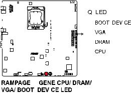
7.Q LED
Q LEDs check key components (CPU, DRAM, VGA card, and booting devices) in sequence during motherboard booting process. If an error is found , the corresponding LED will continue lighting until the problem is solved. This user-friendly design provides an intuitional way to locate the root problem within a second.
|
|
|
|
|
|
|
|
|
|
|
|
|
|
|
|
|
|
|
|
|
|
|
|
|
|
|
|
|
|
|
|
|
|
|
|
|
|
|
|
|
|
|
|
|
|
|
|
|
|
|
|
|
|
|
|
|
|
|
|
|
|
|
|
|
|
|
|
|
|
|
|
|
|
|
|
|
|
|
|
|
|
|
|
|
|
|
|
|
|
|
|
|
|
|
|
|
|
|
|
|
|
|
|
|
|
|
|
|
|
|
|
|
|
|
|
|
|
|
|
|
|
|
|
|
|
|
|
|
|
|
|
|
|
|
|
|
|
|
|
|
|
|
|
|
|
|
|
|
|
|
|
|
|
|
|
|
|
|
|
|
|
|
|
|
|
|
|
|
|
|
|
|
|
|
|
|
|
|
|
|
|
|
|
|
|
|
|
|
|
|
|
|
|
|
|
|
|
|
|
|
|
|
|
|
|
|
|
|
|
|
|
|
|
|
|
|
|
|
|
|
|
|
|
|
|
|
|
|
|
|
|
|
|
|
|
|
|
|
|
|
|
|
|
|
|
|
|
|
|
|
|
|
|
|
|
|
|
|
|
|
|
|
|
|
|
|
|
|
|
|
|
|
|
|
|
|
|
|
|
|
|
|
|
|
|
|
|
|
|
|
|
|
|
|
|
|
|
|
|
|
|
|
|
|
|
|
|
|
|
|
|
|
|
|
|
|
|
|
|
|
|
|
|
|
|
|
|
|
|
|
|
|
|
|
|
|
|
|
|
|
|
|
|
|
|
|
|
|
|
|
|
|
|
|
|
|
|
|
|
|
|
|
|
|
|
|
|
|
|
|
|
|
|
|
|
|
|
|
|
|
|
|
|
|
|
|
|
|
|
|
|
|
|
|
|
|
|
|
|
|
|
|
|
|
|
|
|
|
|
|
|
|
|
|
|
|
|
|
|
|
|
|
|
|
|
|
|
|
|
|
|
|
|
|
|
|
|
|
|
|
|
|
|
|
|
|
|
|
|
|
|
|
|
|
|
|
|
|
|
|
|
|
|
|
|
|
|
|
|
|
|
|
|
|
|
|
|
|
|
|
|
|
|
|
|
|
|
|
|
|
|
|
|
|
|
|
|
|
|
|
|
|
|
|
|
|
|
|
|
|
|
|
|
|
|
|
|
|
|
|
|
|
|
|
|
|
|
|
|
|
|
|
|
|
|
|
|
|
|
|
|
|
|
|
|
|
|
|
|
|
|
|
|
|
|
|
|
|
|
|
|
|
|
|
|
|
|
|
|
|
|
|
|
|
|
|
|
|
|
|
|
|
|
|
|
|
|
|
|
|
|
|
|
|
|
|
|
|
|
|
|
|
|
|
|
|
|
|
|
|
|
|
|
|
|
|
|
|
|
|
|
|
|
|
|
|
|
|
|
|
|
|
|
|
|
|
|
|
|
|
|
|
|
|
|
|
|
|
|
|
|
|
|
|
|
|
|
|
|
|
|
|
|
|
|
|
|
|
|
|
|
|
|
|
|
|
|
|
|
|
|
|
|
|
|
2-6 |
|
|
|
|
|
|
|
|
|
|
|
|
|
|
|
|
|
|
|
|
|
|
|
|
|
|
|
|
|
|
|
|
|
|
|
|
|
|
|
|
|
|
|
|
|
Chapter 2: Hardware information |
||
 Loading...