


 ® P3B-F
Pentium® III / II / CeleronTM
Motherboard
USER’S MANUAL

USER'S NOTICE
No part of this manual, including the products and software described in it, may be reproduced, transmitted, transcribed, stored in a retrieval system, or translated into any language in any form or by any means, except documentation kept by the purchaser for backup purposes, without the express written permission of ASUSTeK COMPUTER INC. (“ASUS”).
ASUS PROVIDES THIS MANUAL “AS IS” WITHOUT WARRANTY OF ANY KIND, EITHER EXPRESS OR IMPLIED, INCLUDING BUT NOT LIMITED TO THE IMPLIED WARRANTIES OR CONDITIONS OF MERCHANTABILITY OR FITNESS FOR A PARTICULAR PURPOSE. IN NO EVENT SHALL ASUS, ITS DIRECTORS, OFFICERS, EMPLOYEES OR AGENTS BE LIABLE FOR ANY INDIRECT, SPECIAL, INCIDENTAL, OR CONSEQUENTIAL DAMAGES (INCLUDING DAMAGES FOR LOSS OF PROFITS, LOSS OF BUSINESS, LOSS OF USE OR DATA, INTERRUPTION OF BUSINESS AND THE LIKE), EVEN IF ASUS HAS BEEN ADVISED OF THE POSSIBILITY OF SUCH DAMAGES ARISING FROM ANY DEFECT OR ERROR IN THIS MANUAL OR PRODUCT.
Product warranty or service will not be extended if: (1) the product is repaired, modified or altered, unless such repair, modification of alteration is authorized in writing by ASUS; or (2) the serial number of the product is defaced or missing.
Products and corporate names appearing in this manual may or may not be registered trademarks or copyrights of their respective companies, and are used only for identification or explanation and to the owners’ benefit, without intent to infringe.
•QuickStart and JumperFree are trademarks of ASUSTeK Computer Incorporated.
•Intel, LANDesk, and Pentium are registered trademarks of Intel Corporation.
•Celeron is a trademark of Intel Corporation.
•IBM and OS/2 are registered trademarks of International Business Machines.
•Symbios is a registered trademark of Symbios Logic Corporation.
•Windows and MS-DOS are registered trademarks of Microsoft Corporation.
•Adobe and Acrobat are registered trademarks of Adobe Systems Incorporated.
The product name and revision number are both printed on the product itself. Manual revisions are released for each product design represented by the digit before and after the period of the manual revision number. Manual updates are represented by the third digit in the manual revision number.
For previous or updated manuals, BIOS, drivers, or product release information, contact ASUS at http://www.asus.com.tw or through any of the means indicated on the following page.
SPECIFICATIONS AND INFORMATION CONTAINED IN THIS MANUAL ARE FURNISHED FOR INFORMATIONAL USE ONLY, AND ARE SUBJECT TO CHANGE AT ANY TIME WITHOUT NOTICE, AND SHOULD NOT BE CONSTRUED AS A COMMITMENT BY ASUS. ASUS ASSUMES NO RESPONSIBILITY OR LIABILITY FOR ANY ERRORS OR INACCURACIES THAT MAYAPPEAR IN THIS MANUAL, INCLUDING THE PRODUCTS AND SOFTWARE DESCRIBED IN IT.
Copyright © 1999 ASUSTeK COMPUTER INC. All Rights Reserved.
Product Name: |
ASUS P3B-F |
Manual Revision: |
1.04 E467 |
Release Date: |
October 1999 |
|
|
2 |
ASUS P3B-F User’s Manual |

ASUS CONTACT INFORMATION
ASUSTeK COMPUTER INC. (Asia-Pacific)
Marketing
Address: |
150 Li-Te Road, Peitou, Taipei, Taiwan 112 |
Telephone: |
+886-2-2894-3447 |
Fax: |
+886-2-2894-3449 |
Email: |
info@asus.com.tw |
Technical Support
MB/Others (Tel): |
+886-2-2890-7121 (English) |
|
Notebook (Tel): |
+886-2-2890-7122 |
(English) |
Desktop/Server (Tel):+886-2-2890-7123 |
(English) |
|
Fax: |
+886-2-2895-9254 |
|
Email: |
tsd@asus.com.tw |
|
WWW: |
www.asus.com.tw |
|
FTP: |
ftp.asus.com.tw/pub/ASUS |
|
ASUS COMPUTER INTERNATIONAL (America)
Marketing
Address: |
6737 Mowry Avenue, Mowry Business Center, Building 2 |
|
Newark, CA 94560, USA |
Fax: |
+1-510-608-4555 |
Email: |
tmd1@asus.com |
Technical Support
Fax: |
+1-510-608-4555 |
BBS: |
+1-510-739-3774 |
Email: |
tsd@asus.com |
WWW: |
www.asus.com |
FTP: |
ftp.asus.com/Pub/ASUS |
ASUS COMPUTER GmbH (Europe)
Marketing
Address: |
Harkortstr. 25, 40880 Ratingen, BRD, Germany |
Fax: |
+49-2102-442066 |
Email: |
sales@asuscom.de (for marketing requests only) |
Technical Support
Hotline: |
MB/Others: +49-2102-9599-0 Notebook: +49-2102-9599-10 |
Fax: |
+49-2102-9599-11 |
Support (Email): |
www.asuscom.de/de/support (for online support) |
WWW: |
www.asuscom.de |
FTP: |
ftp.asuscom.de/pub/ASUSCOM |
ASUS P3B-F User’s Manual |
3 |

CONTENTS
1. INTRODUCTION .............................................................................. |
7 |
||
1.1 |
How This Manual Is Organized .................................................. |
7 |
|
1.2 |
Item Checklist ............................................................................. |
7 |
|
2. FEATURES ......................................................................................... |
8 |
||
2.1 |
The ASUS P3B-F Motherboard .................................................. |
8 |
|
|
2.1.1 |
Specifications .................................................................. |
8 |
|
2.1.2 |
Special Features ............................................................. |
10 |
|
2.1.3 |
Performance Features .................................................... |
10 |
|
2.1.4 |
Intelligence .................................................................... |
11 |
2.2 |
Motherboard Parts ..................................................................... |
12 |
|
3. HARDWARE SETUP ...................................................................... |
14 |
||
3.1 |
Motherboard Layout ................................................................. |
14 |
|
3.2 |
Layout Contents ........................................................................ |
15 |
|
3.3 |
Hardware Setup Procedure ....................................................... |
16 |
|
3.4 |
Motherboard Settings ................................................................ |
16 |
|
3.5 |
System Memory (DIMM) ......................................................... |
21 |
|
|
3.5.1 |
General DIMM Notes .................................................... |
21 |
|
3.5.2 |
DIMM Memory Installation .......................................... |
22 |
3.6 |
Central Processing Unit (CPU) ................................................. |
23 |
|
|
3.6.1 |
Universal Retention Mechanism ................................... |
23 |
|
3.6.3 |
Installing the Processor .................................................. |
24 |
|
3.6.2 |
Heatsinks ....................................................................... |
24 |
|
3.6.4 Recommended Heatsinks for Slot 1 Processors ............ |
27 |
|
|
3.6.5 |
Precautions .................................................................... |
28 |
3.7 |
Expansion Cards ....................................................................... |
29 |
|
|
3.7.1 Expansion Card Installation Procedure ......................... |
29 |
|
|
3.7.2 Assigning IRQs for Expansion Cards ............................ |
29 |
|
|
3.7.4 Accelerated Graphics Port (AGP) ................................. |
31 |
|
|
3.7.3 Assigning DMA Channels for ISA Cards ...................... |
31 |
|
3.8 |
External Connectors .................................................................. |
32 |
|
3.9 |
Power Connection Procedures .................................................. |
41 |
|
4. BIOS SETUP .................................................................................... |
42 |
||
4.1 |
Managing and Updating Your BIOS ......................................... |
42 |
|
|
4.1.1 Upon First Use of the Computer System ....................... |
42 |
|
|
4.1.2 Updating BIOS Procedures (only when necessary) ...... |
43 |
|
4 |
ASUS P3B-F User’s Manual |

CONTENTS
4.2 |
BIOS Setup Program ................................................................ |
45 |
|
|
4.2.1 |
BIOS Menu Bar ............................................................. |
46 |
|
4.2.2 |
Legend Bar .................................................................... |
46 |
4.3 |
Main Menu ................................................................................ |
48 |
|
|
4.3.1 Primary & Secondary Master/Slave .............................. |
49 |
|
4.4 |
Advanced Menu ........................................................................ |
54 |
|
|
4.4.1 |
Chip Configuration ........................................................ |
58 |
|
4.4.2 |
I/O Device Configuration .............................................. |
60 |
|
4.4.3 |
PCI Configuration ......................................................... |
62 |
|
4.4.4 |
Shadow Configuration ................................................... |
65 |
4.5 |
Power Menu .............................................................................. |
66 |
|
|
4.5.1 |
Power Up Control .......................................................... |
68 |
|
4.5.2 |
Hardware Monitor ......................................................... |
70 |
4.6 |
Boot Menu ................................................................................ |
71 |
|
4.7 |
Exit Menu ................................................................................. |
73 |
|
5. SOFTWARE SETUP ....................................................................... |
75 |
||
5.1 |
Operating Systems .................................................................... |
75 |
|
5.2 |
P3B-F Support CD .................................................................... |
75 |
|
5.3 |
Intel LDCM Administrator Setup ............................................. |
77 |
|
5.4 |
Intel LDCM Client Setup .......................................................... |
78 |
|
5.5 |
Install ASUS PC Probe Vx.xx .................................................. |
80 |
|
5.6 |
Install ASUS Update Vx.xx ...................................................... |
81 |
|
5.7 |
Install PC-Cillin 98 Vx.xx ........................................................ |
82 |
|
5.8 |
Install ADOBE AcroBat Reader Vx.x ...................................... |
83 |
|
5.9 |
Uninstalling Programs .............................................................. |
84 |
|
6. SOFTWARE REFERENCE ............................................................ |
85 |
||
6.1 |
Intel LANDesk Client Manager ................................................ |
85 |
|
6.2 |
ASUS PC Probe ........................................................................ |
91 |
|
7. APPENDIX |
........................................................................................ |
97 |
|
7.1 |
UltraDMA/66 PCI Card ............................................................ |
97 |
|
7.2 |
PCI-L101 Fast Ethernet Card ................................................. |
109 |
|
7.3 |
ASUS S370 Series CPU Card ................................................. |
111 |
|
ASUS P3B-F User’s Manual |
5 |

FCC & DOC COMPLIANCE
Federal Communications Commission Statement
This device complies with FCC Rules Part 15. Operation is subject to the following two conditions:
•This device may not cause harmful interference, and
•This device must accept any interference received, including interference that may cause undesired operation.
This equipment has been tested and found to comply with the limits for a Class B digital device, pursuant to Part 15 of the FCC Rules. These limits are designed to provide reasonable protection against harmful interference in a residential installation. This equipment generates, uses and can radiate radio frequency energy and, if not installed and used in accordance with manufacturer's instructions, may cause harmful interference to radio communications. However, there is no guarantee that interference will not occur in a particular installation. If this equipment does cause harmful interference to radio or television reception, which can be determined by turning the equipment off and on, the user is encouraged to try to correct the interference by one or more of the following measures:
•Re-orient or relocate the receiving antenna.
•Increase the separation between the equipment and receiver.
•Connect the equipment to an outlet on a circuit different from that to which the receiver is connected.
•Consult the dealer or an experienced radio/TV technician for help.
WARNING! Any changes or modifications to this product not expressly approved by the manufacturer could void any assurances of safety or performance and could result in violation of Part 15 of the FCC Rules.
Reprinted from the Code of Federal Regulations #47, part 15.193, 1993. Washington DC: Office of the Federal Register, National Archives and Records Administration, U.S. Government Printing Office.
Canadian Department of Communications Statement
This digital apparatus does not exceed the Class B limits for radio noise emissions from digital apparatus set out in the Radio Interference Regulations of the Canadian Department of Communications.
This Class B digital apparatus complies with Canadian ICES-003.
Cet appareil numérique de la classe B est conforme à la norme NMB-003 du Canada.
6 |
ASUS P3B-F User’s Manual |

1.INTRODUCTION
1.1How This Manual Is Organized
This manual is divided into the following sections:
1. |
Introduction |
Manual information and checklist |
2. |
Features |
Information and specifications concerning this product |
3. |
Hardware Setup |
Instructions on setting up the motherboard and jumpers |
4. |
BIOS Setup |
Instructions on setting up the BIOS software |
5.Software Setup Instructions on setting up the included support software
6.Software Reference Reference material for the included support software
7. Appendix Optional items
1.2 Item Checklist
Please check that your package is complete. If you discover damaged or missing items, please contact your retailer.
(1) ASUS Motherboard
(1) Universal Retention Mechanism for SECC2/SECC/SEPP processors
(1) Ribbon cable for master and slave IDE drives
(1) Ribbon cable for (1) 5.25” and (2) 3.5” floppy drives
(1) Bag of spare jumper caps
(1) Support CD with drivers and utilities
(1) This Motherboard User’s Manual
ASUS IrDA-compliant infrared module (optional)
ASUS S370 Series CPU cards (optional)
ASUS PCI-L101 Wake-On-LAN 10/100 ethernet card (optional)
Manual / Checklist
1. INTRODUCTION
ASUS P3B-F User’s Manual |
7 |

Specifications |
2.FEATURES |
|
|
2.FEATURES
2.1The ASUS P3B-F Motherboard
The ASUS P3B-F is carefully designed for the demanding PC user who wants advanced features processed by the fastest CPU.
2.1.1 Specifications
•Multi-Speed: Supports Intel Pentium® III (450MHz and faster), Pentium® II (233MHz to 450MHz), and CeleronTM (266MHz and faster) processors.
•Intel AGPset: Features Intel’s 440BX AGPset with I/O subsystems and front-side bus (FSB) platform, which boosts the traditional 66MHz external bus speed to 100MHz.
•Multi-Cache: Supports processors with 512, 256, 128, or 0KB Pipelined Burst Level 2 cache.
•PC100 Memory Support: Equipped with four DIMM sockets to support Intel PC100-compliant SDRAMs (8, 16, 32, 64, 128, or 256MB) up to 1024MB. These new SDRAMs are necessary to meet the critical enhanced 100MHz bus speed requirement.
• JumperFree™ BIOS: Allows processor settings and easy overclocking of frequency and Vcore voltages all through BIOS setup when JumperFree™ mode is enabled. Easy-to-use DIP switches intsead of jumpers are provided to manually setup the processor.
•Smart BIOS: 2Mb firmware provides Vcore and CPU/SDRAM frequency adjustments, boot block write protection, and HD/SCSI/MO/ZIP/CD/Floppy boot selection. Power supply is autodetected to enable/disable suspend-to-RAM and KB/PS/2 mouse power up, eliminating the need to make jumper adjustments.
•Multi-device Wake Up: Supports modem wake up, keyboard/PS/2 mouse wake up, and LAN card wake up functions from sleep or soft-off mode.
•PC Health Monitoring: Provides an easier way to examine and manage system status information, such as CPU and system voltages, temperatures, and fan status through the onboard hardware ASIC and the bundled LDCM from Intel or PC Probe from ASUS.
•Enhanced ACPI & Anti-Boot Virus Protection: Programmable BIOS (flash EEPROM), offering enhanced ACPI for Windows 98 compatibility, built-in firm- ware-based virus protection, and autodetection of most devices for virtually automatic setup.
•AGP Slot: Supports an Accelerated Graphics Port card for high performance, component level interconnect targeted at 3D graphical display applications using a 1X or 2X mode bus.
•SMBus: Features the System Management Bus interface, which is used to physically transport commands and information between SMBus devices.
8 |
ASUS P3B-F User’s Manual |

2. FEATURES
• PCI & ISA Expansion Slots: Provides options of five 32-bit PCI (rev 2.2) with |
|
|
two 16-bit ISA expansion slots, six PCI with one ISA, and six PCI with no ISA. |
|
|
All PCI slots can support Bus Master PCI cards, such as SCSI or LAN cards. |
|
|
(PCI supports up to 133MB/s maximum throughput.) |
|
|
• Multi-I/O: Provides two high-speed UART compatible serial ports and one paral- |
|
|
lel port with EPP and ECP capabilities. UART2 can also be directed from COM2 |
|
|
to the Infrared Module for wireless connections. |
|
|
• UltraDMA/33 Bus Master IDE: Comes with an onboard PCI Bus Master IDE con- |
|
|
FEATURES2. Specifications |
||
aged in a Single Edge Contact Cartridge (SECC2/SECC) or a CeleronTM proces- |
||
troller with two connectors that support four IDE devices in two channels. Supports |
|
|
UltraDMA/33, PIO Modes 3 and 4, and Bus Master IDE DMA Mode 2, as well as |
|
|
Enhanced IDE devices, such asTape Backup, CD-ROM, CD-R/W, and LS-120 drives. |
|
|
• Universal Retention Mechanism: Supports a Pentium® III / II processor pack- |
|
|
sor packaged in a Single Edge Processor Package (SEPP). |
|
|
• Wake-On-LAN Connector: Supports Wake-On-LAN activity through an op- |
|
|
tional ASUS PCI-L101 10/100 Fast Ethernet PCI card (see 7.1 PCI-L101 Fast |
|
|
Ethernet Card) or a similar ethernet card. |
|
|
• Wake-On-Ring Connector: Supports Wake-On-Ring activity through a PCI |
|
|
modem card which supports a WOR connector. |
|
|
• IrDA: Supports an optional infrared port module for a wireless interface. |
|
|
• Onboard LED: The onboard LED will light up when there is standby power to |
|
|
the PCI bus. This acts as a reminder to the user to turn OFF the power before |
|
|
plugging and unplugging devices so as not to damage the motherboard, periph- |
|
|
erals, and/or components. |
|
ASUS P3B-F User’s Manual |
9 |

Specifications |
2.FEATURES |
|
|
2.FEATURES
2.1.2Special Features
•ACPI Ready: Advanced Configuration Power Interface (ACPI) provides more Energy Saving Features for operating systems that support OS Direct Power Management (OSPM) functionality. With these features implemented in the OS, PCs can be ready around the clock, yet satisfy all the energy saving standards. To fully utilize the benefits of ACPI, an ACPI-supported OS such as Windows 98 must be used.
•Suspend and Go: Suspend-to-RAM (STR) provides maximum power savings (average of 5 watts) as an alternative to leaving the computer ON and QuickStartTM so that you do not fall asleep waiting for system bootup (Suspend-to-RAM requires OS support and does not support ISA cards; ISA cards may fail to work coming out of STR mode).
•Easy Installation: Incorporates BIOS that supports autodetection of hard disk drives, PS/2 mouse, and Plug and Play devices to make the setup of hard disk drives, expansion cards, and other devices virtually automatic.
•PC’99 Compliant: Both the BIOS and hardware levels of ASUS smart series motherboards meet PC’99 compliancy. The new PC’99 requirements for systems and components are based on the following high-level goals: Support for Plug and Play compatibility and power management for configuring and managing all system components, and 32-bit device drivers and installation procedures for Windows95/98/NT . Color-coded connectors and descriptive icons make identification easy as required by PC’99.
•Symbios SCSI BIOS: Supports optional ASUS SCSI controller cards through the onboard SYMBIOS firmware.
2.1.3 Performance Features
•Concurrent PCI: Concurrent PCI allows multiple PCI transfers from PCI master busses to the memory and processor.
•Double the IDE Transfer Speed: ASUS smart series motherboards with Intel chipsets improve IDE transfer rate using Bus Master UltraDMA/33 IDE which can handle data transfers up to 33MB/s.
•SDRAM Optimized Performance: Supports the new generation memory - Synchronous Dynamic Random Access Memory (SDRAM) which increases the data transfer rate to 800MB/s max using PC100-compliant SDRAM.
10 |
ASUS P3B-F User’s Manual |
2.FEATURES
2.1.4Intelligence
•Auto Fan Off: The system fans will power off automatically even in sleep mode. This function reduces both energy consumption and system noise, and is an important feature in implementing silent PC systems.
•Dual Function Power Button: Pushing the power button for less than 4 seconds when the system is in the working state places the system into one of two states: sleep mode or soft-off mode, depending on the BIOS or OS setting (see PWR Button < 4 Secs in 4.5 Power Menu). When the power button is pressed for more than 4 seconds, the system enters the soft-off mode regardless of the BIOS setting.
•Fan Status Monitoring and Alarm: To prevent system overheat and system damage, the CPU, power supply, and system fans can be monitored for RPM and failure. All fans are set for its normal RPM range and alarm thresholds.
•PS/2 Keyboard/Mouse Power Up: Keyboard/Mouse Power Up can be enabled or disabled to allow the computer to be powered on by pressing the space bar on the keyboard or moving the mouse.
•Message LED (requires ACPI OS support): Turbo LEDs now act as information providers. Through the way a particular LED illuminates, the user can determine if there are messages waiting in the mailbox. A simple glimpse provides useful information to the user.
•Remote Ring On (requires modem): This allows a computer to be turned on remotely through an internal or external modem. With this benefit on-hand, users can access vital information from their computers from anywhere in the world!
•System Resources Alert: Today’s operating systems such as Windows 95/98/ NT and OS/2, require much more memory and hard drive space to present enormous user interfaces and run large applications. The system resource monitor will warn the user before the system resources are used up to prevent possible application crashes. Suggestions will give the user information on managing their limited resources more efficiently.
•Temperature Monitoring and Alert: CPU temperature is monitored by the ASUS ASIC through the CPU’s internal thermal diode (on Pentium III, Pentium II (Deschutes), and PPGA370 Celeron in conjunction with the ASUS S370-D or S370-L CPU card) to prevent system overheat and system damage.
•Voltage Monitoring and Alert: System voltage levels are monitored to ensure stable voltage to critical motherboard components. Voltage specifications are more critical for future processors, so monitoring is necessary to ensure proper system configuration and management.
•Chassis Intrusion Detection: Supports chassis-intrusion monitoring through the ASUS ASIC. A chassis intrusion event is kept in memory on battery power for more protection.
2.FEATURES |
Specifications |
|
|
ASUS P3B-F User’s Manual |
11 |

Specifications |
2.FEATURES |
|
|
2.FEATURES
2.2Motherboard Parts
1ATX Power Connector
2Slot 1 CPU Socket
3Intel 440BX AGPset
44 DIMM Sockets
5IDE Connectors
6ASUS ASIC with hardware monitor
7Floppy Disk Drive Connector
8Function DIP Switches
9Intel PIIX4E PCIset
10Onboard LED
11Wake-On-Ring Connector
121 or 2 ISA Slots (on ISA model only)
13Programmable Flash EEPROM
14Wake-On-LAN Connector
15Multi I/O Chip
165 or 6 PCI Slots
17Accelerated Graphics Port
18Serial Port Connector
19Parallel Port Connector
20Serial Port Connector
212 USB Connectors
22T: PS/2 Mouse Connector
B:PS/2 Keyboard Connector
12 |
ASUS P3B-F User’s Manual |

22
21
20
19
18
17
16
15
14
13
12
2. FEATURES
1 |
2 |
3 |
4 |
5 |
Motherboard Parts
2. FEATURES
11 |
10 |
9 |
8 |
7 |
6 |
ASUS P3B-F User’s Manual |
13 |
Layout Board
.3 SETUP H/W
3.HARDWARE SETUP
3.1Motherboard Layout
|
|
|
|
|
|
|
|
|
|
|
PS2 |
MouseTOP: |
ATXPWR |
|
|||
|
|
KBMS |
Keyboard |
|
|
|
||
|
|
|
|
|
BOTTOM: |
Connector |
|
|
|
|
|
|
|
|
|
|
|
|
|
|
|
USB 2 |
|
|
||
|
|
USB |
|
|
||||
|
|
|
|
TOP: |
|
|
|
|
|
|
|
|
USB 1 |
|
|
|
|
|
|
|
|
BOTTOM: |
|
|
|
|
|
|
|
|
|
|
Power |
|
|
|
|
|
|
|
|
|
|
|
|
|
COM1 |
|
|
|
|
|
|
|
|
|
|
|
|
ATX |
|
|
|
|
Printer Port |
|
|
Slot 1 |
|||
|
|
|
|
|
||||
|
|
|
|
|
||||
|
|
|
|
|
||||
|
|
|
|
|
|
|
|
|
|
|
|
|
|
|
|
|
|
|
|
|
|
|
|
|
|
|
|
|
|
|
|
|
|
|
|
|
|
COM2 |
|
|
|
|
||
|
|
|
|
|
||||
|
|
|
|
|
JTPWR |
|
||
|
|
|
|
|
|
|||
|
|
|
|
|
|
|
|
|
CR2032 3V
Lithium Cell
(CMOS Power)
|
|
|
PWR_FAN |
|
|
|
|
|
|
|
|
|
|
|
|
|
|
|
|
|
|
|
||||||
|
|
|
|
|
|
|
|
|
|
|
|
|
|
|
|
JP20 |
||||||||||||
|
|
|
|
|
|
|
|
|
|
|
|
|
|
|
|
|
|
|
|
|
|
|
||||||
|
|
|
|
|
|
|
|
|
|
|
|
|
|
|
|
|
|
|
|
|
|
|
(VIO) |
|||||
|
|
|
|
CPU_FAN |
|
|
|
|
|
bit, 168 pin module) |
|
bit, 168 pin module) |
|
|
bit, 168 pin module) |
|
|
bit, 168 pin module) |
|
|
|
|
|
|
|
|
||
|
|
|
|
|
|
|
|
|
|
|
|
|
|
|
|
|
|
|
|
|
|
|||||||
|
|
|
|
|
|
|
|
|
|
|
|
|
|
|
|
|
|
|
|
|
|
|
||||||
|
|
|
|
Intel |
|
|
|
|
|
|
|
|
|
|
|
|
|
|||||||||||
|
|
|
|
|
|
|
(64/72 |
|
(64/72 |
|
|
(64/72 |
|
|
(64/72 |
|
|
|
|
|
|
|
|
|||||
|
|
|
|
440BX |
|
|
|
|
|
|
|
|
|
|
|
|
|
|
|
|
||||||||
|
|
|
|
AGPset |
|
|
|
0 |
|
1 |
|
|
2 |
|
|
3 |
|
|
|
|
|
|
|
|
||||
|
|
|
|
|
|
|
Row |
DIMM Socket |
|
DIMM Socket |
|
|
DIMM Socket |
|
|
DIMM Socket |
|
SECONDARYIDE |
|
|
|
|
|
PRIMARY IDE |
||||
|
|
|
|
|
|
|
|
|
|
|
|
|
|
|
||||||||||||||
|
|
|
|
|
|
|
0 |
1 |
|
2 |
|
3 |
|
4 |
5 |
|
6 |
7 |
|
|
|
|
|
|||||
|
|
|
|
|
|
|
|
|
|
|
|
|
|
|
|
|||||||||||||
|
|
|
|
|
|
|
|
|
|
|
|
|
|
|
|
|||||||||||||
Accelerated Graphics Port |
|
|
|
|
|
|
|
|
|
|
|
|
|
|
|
|
||||||||||||
|
|
|
|
|
|
|
|
|
|
|
|
|
|
|
|
|||||||||||||
|
|
|
|
|
|
|
|
|
|
|
|
|
|
|
|
|||||||||||||
|
|
|
|
|
|
|
|
|
|
|
|
|
|
|
|
|
|
|
|
|
|
|
|
|
|
|
|
|
|
|
|
|
|
|
|
|
|
|
|
|
|
|
|
|
|
|
|
|
|
|
|
|
|
|
|
||
|
|
|
|
|
|
|
|
|
|
|
|
|
|
|
|
DIP |
|
|
|
DSW |
|
|
|
|
|
|
||
|
|
|
|
|
|
|
|
|
|
|
|
|
|
Switches |
|
|
|
|
|
|
|
|||||||
|
|
|
|
|
|
|
|
|
|
|
|
|
|
|
|
|
|
|
|
|
|
|||||||
|
PCI Slot 1 |
|
R |
|
|
|
-F |
Multi-I/O |
PCI Slot 2 |
FLOPPY |
P3B |
|
|||
|
|
Wake-On-LAN |
|
|
|
|
|
|
|
|
CHASSIS |
|
|
|
|
|
|
|
|
|
|
|
|
|
|
|
|
|
|||
Connector |
|
|
|
|
|
|
|
|
|
|
|
|
|
|
|
|
|
|
|
|
|
|
|
|
|
|
|||
|
|
|
|
|
|
|
|
|
|
|
|
|
|
|
|
|
|
|
|
|
|
|
|
|
|
||||
(WOL_CON) |
|
|
|
|
|
|
|
|
|
|
|
|
|
|
|
|
|
|
|
|
|
|
|
|
|
|
|
||
|
|
|
|
|
|
|
|
PCI Slot 3 |
|
|
|
|
|
|
|
|
|
|
|
|
|
|
|
|
|
|
|||
|
|
|
|
|
|
|
|
|
|
|
|
|
|
|
|
|
|
|
|
|
|
|
|
|
|
|
|
|
|
|
EEPROMFlash BIOS)(Programable |
|
|
|
|
|
|
|
SMB |
Intel |
|
|
|
|
|
|
|
|
|
|
|
|
|
|
|
|
|||
|
|
|
|
|
|
|
|
|
|
|
|
|
|
|
|
|
|
|
|
|
|
|
|
||||||
|
|
|
|
|
|
|
|
|
PCI Slot 5 |
PIIX4E |
|
CHA_FAN |
|
||||||||||||||||
|
|
|
|
|
|
|
|
|
|
|
PCI Slot 4 |
|
CLRTC |
|
|
ASUS |
|
||||||||||||
|
|
|
|
|
|
|
|
|
|
|
|
PCIset |
|
|
|
ASIC |
|
||||||||||||
|
|
|
|
|
|
|
WOR |
|
|
|
|
|
|
|
|
|
|
with |
|
||||||||||
|
|
|
|
|
|
|
|
|
|
|
|
|
|
|
|
|
|
||||||||||||
|
|
|
|
|
|
|
|
|
|
|
|
|
|
Hardware |
|
||||||||||||||
|
|
|
|
|
|
|
|
|
|||||||||||||||||||||
|
|
|
|
|
|
|
|
|
|
|
|
|
|
|
|
|
|
|
|
|
|
Monitor |
|
||||||
|
|
|
|
|
|
|
|
|
|
|
|
|
|
|
|
|
|
|
|
|
|
|
|||||||
|
|
|
|
|
|
|
|
|
|
|
|
|
|
|
|
|
|
|
|
|
|
|
|
|
|
|
|
|
|
|
|
|
|
|
|
|
|
|
|
|
|
|
|
|
|
|
|
|
|
|
|
|
|
|
PANEL |
||||
|
|
|
|
|
|
|
|
|
|
|
|
|
|
|
|
|
|
|
|
|
|
|
|
|
|||||
|
|
|
|
|
|
|
|
|
|
|
|
|
|
|
|
|
|
|
|
|
|
|
|
|
|||||
|
|
|
|
|
|
|
|
|
|
|
ISA Slot 1 |
|
|
|
|
|
|
|
|
|
|
|
|
|
|||||
|
|
|
|
|
|
|
|
|
|
|
|
|
|
|
|
|
|
|
|
|
|
|
|
|
|
|
|
|
|
|
|
|
|
|
|
|
|
|
|
|
PCI Slot 6 |
|
JEN IDELED |
|
|
|
|
|
|
||||||||||
|
|
|
|
|
|
|
|
IR |
|
||||||||||||||||||||
|
|
|
|
|
|
|
|
|
|
|
|
|
|
|
|
|
|
||||||||||||
ISA Slot 2
(Grayed item are optional at the time of purchase.)
14 |
ASUS P3B-F User’s Manual |

3.HARDWARE SETUP
3.2Layout Contents
Motherboard Settings
1) DSW-Switch 6 |
p. 17 AGP Bus Frequency Setting |
2)DSW-Switches 7-10 p. 18 CPU External Clock (BUS) Frequency Selection
3)DSW-Switches 1-4 p. 19 CPU Core:BUS Frequency Multiple
4) |
JEN |
p. 20 |
JumperFreeTM Mode Setting (Enable/Disable) |
5) |
JP20 |
p. 20 |
I/O Voltage Setting (3.50/3.65 Volt) |
Expansion Slots/Sockets
1) |
System Memory |
p. 21 |
System Memory Support |
2) |
DIMM0,1,2,3 |
p. 22 |
DIMM Memory Module Support |
3) |
Slot 1 |
p. 23 |
CPU Support |
4) |
SLOT1, SLOT2 |
p. 28 |
16-bit ISA Bus Expansion Slots (optional) |
5) |
PCI1,2,3,4,5 ,6 |
p. 28 |
32-bit PCI Bus Expansion Slots (optional PCI6) |
6) |
AGP |
p. 29 |
Accelerated Graphics Port |
Connectors
1) |
PS2KBMS |
p. 30 PS/2 Mouse Port Connector (6 pin-female) |
|
2) |
PS2KBMS |
p. 30 PS/2 Keyboard Port Connector (6-pin female) |
|
3) |
PARALLEL |
p. 31 Parallel (Printer) Port Connector (25-pin female) |
|
4) |
COM1, COM2 |
p. 31 Serial Port COM1 & COM2 (two 9-pin male) |
|
5) |
FLOPPY |
p. 31 Floppy Drive Port Connector (34 pins) |
|
6) |
USB |
p. 32 |
Universal Serial Bus Port Connectors 1 & 2 (Two 4-pin female) |
7) |
Primary/Secondary IDE |
p. 32 Primary/Secondary IDE Connectors (Two 40-1 pins) |
|
8) |
IDELED |
p. 33 IDE Device Activity LED (2 pins) |
|
9) |
CHA_, PWR_, CPU_FAN p. 33 |
Chassis, Power Supply, CPU FanPowerConnectors (3 pins) |
|
10) |
IR |
p. 34 IrDA-Compliant Infrared Module Connector (5 pins) |
|
11) |
SMB |
p. 34 |
SMBus Connector (3 pins) |
12) |
WOL_CON |
p. 35 |
Wake-On-LAN Connector (3 pins) |
13) |
WOR |
p. 35 |
Wake-On-Ring Connector (2 pins) |
14) |
CHASSIS |
p. 36 Chassis Intrusion Alarm Lead (3 pins) |
|
15) |
PWR.LED (PANEL) |
p. 36 |
System Power LED Lead (3 pins) |
16) |
KEYLOCK (PANEL) |
p. 36 |
Keyboard Lock Switch Lead (2 pins) |
17) |
SPEAKER (PANEL) |
p. 36 System Warning Speaker Connector (4 pins) |
|
18) |
MSG.LED (PANEL) |
p. 36 System Message LED Lead (2 pins) |
|
19) |
SMI (PANEL) |
p. 36 System Management Interrupt Lead (2 pins) |
|
20) |
PWR.SW (PANEL) |
p. 37 |
ATX / Soft-Off Switch Lead (2 pins) |
21) |
RESET (PANEL) |
p. 37 Reset Switch Lead (2 pins) |
|
22) |
ATXPWR |
p. 38 ATX Power Supply Connector (20 pins) |
|
23) |
JTPWR |
p. 38 |
Thermal Sensor Connector |
Layout Contents
3. H/W SETUP
ASUS P3B-F User’s Manual |
15 |

Settings Motherboard
.3 SETUP H/W
3.HARDWARE SETUP
3.3Hardware Setup Procedure
Before using your computer, you must complete the following steps:
1.Check Motherboard Settings
2.Install Memory Modules
3.Install the Central Processing Unit (CPU)
4.Install Expansion Cards
5.Connect Ribbon Cables, Panel Wires, and Power Supply
6.Setup the BIOS Software
3.4 Motherboard Settings
This section explains in detail how to change your motherboard’s function settings through the use of switches and/or jumpers.
WARNING! Computer motherboards and expansion cards contain very delicate Integrated Circuit (IC) chips. To protect them against damage from static electricity, you should follow some precautions whenever you work on your computer.
1.Unplug your computer when working on the inside.
2.Use a grounded wrist strap before handling computer components. If you do not have one, touch both of your hands to a safely grounded object or to a metal object, such as the power supply case.
3.Hold components by the edges and try not to touch the IC chips, leads or connectors, or other components.
4.Place components on a grounded antistatic pad or on the bag that came with the component whenever the components are separated from the system.
16 |
ASUS P3B-F User’s Manual |
3. HARDWARE SETUP
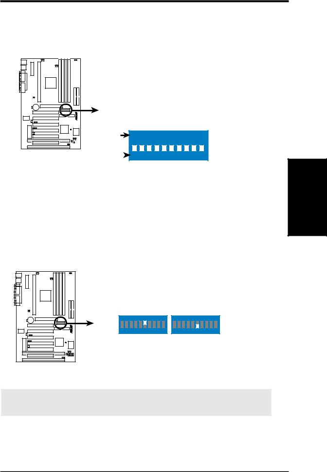
Motherboard Feature Settings (DIP Switches–DSW)
The motherboard’s onboard functions are adjusted through the DIP switches. The white block represents the switch’s position. The example below shows all the switches in the OFF position.
DSW |
1. Frequency Multiple |
||
|
2. Frequency Multiple |
||
|
3. |
Frequency Multiple |
|
|
4. |
Frequency Multiple |
|
|
5. |
(Reserved) |
|
|
6. AGP Frequency Selection |
||
|
7. |
Frequency Selection |
|
|
8. |
Frequency Selection |
|
-F |
9. |
Frequency Selection |
|
P3B |
|||
10. |
Frequency Selection |
||
|
|||
ON |
ON |
||
|
|
|
|
OFF |
|
|
|
|
|
|
|
|
|
|
|
|
|
|
|
|
|
|
|
|
|
|
|
|
|
|
|
|
|
|
|
|
|
|
|
|
|
|
|
|
|
|
|
|
|
|
|
|
|
|
|
|
|
|
|
|
|
|
|
|
|
|
|
|
|
|
|
|
|
|
|
|
|
|
|
|
|
|
|
P3B-F DIP Switches |
|
|
1 2 3 4 5 6 7 8 9 10 |
||||||||||||||||||||||||
|
|||||||||||||||||||||||||||
|
|
|
|||||||||||||||||||||||||
1)AGP Bus Frequency Setting (DSW-Switch 6)
This option sets the frequency ratio between the AGP bus frequency and the DRAM (CPU bus) frequency. The default sets the AGP bus frequency to be 2/3 of the DRAM frequency. When the CPU/DRAM frequency is set to 66MHz, set this switch to [ON]. See the processor table on the next page.
Setting |
DSW-Switch 6 |
|||
DRAM Freq. x 2/3 |
[OFF] (default) |
|||
DRAM Freq. x 1 |
[ON] |
|||
|
|
|
|
|
|
|
|
|
|
|
|
|
|
|
|
|
|
|
|
|
|
|
|
|
|
|
|
|
|
|
|
|
|
|
|
|
|
|
|
|
|
|
|
|
Motherboard Settings
3. H/W SETUP
P3B-F |
ON |
|
|
|
|
|
|
|
|
1 |
2 |
3 |
4 |
5 |
6 |
7 |
8 |
9 10 |
DRAM Freq. x1
ON
1 2 3 4 5 6 7 8 9 10
DRAM Freq. x2/3
P3B-F AGP Bus Frequency Setting
WARNING! AGP bus frequencies above 66MHz exceed the specifications for the AGP interface and are not guaranteed to be stable.
ASUS P3B-F User’s Manual |
17 |
Settings Motherboard
.3 SETUP H/W
3.HARDWARE SETUP
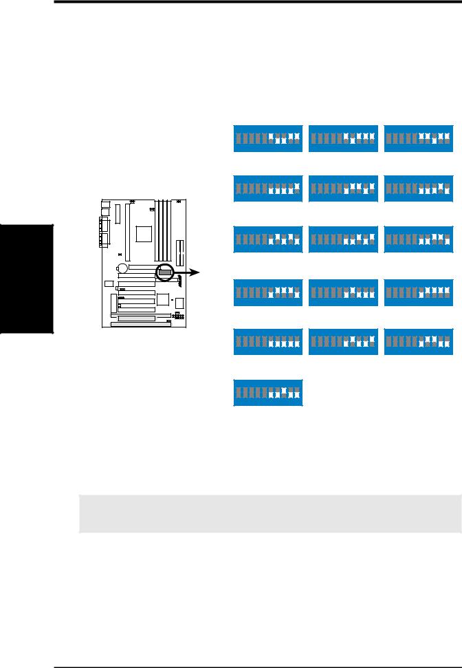
2)CPU External Frequency Selection (DSW-Switches 7-10)
This option tells the clock generator what frequency to send to the CPU, DRAM, and the PCI bus. This allows the selection of the CPU’s External frequency (or BUS Clock). The BUS Clock multiplied by the Frequency Multiple equals the CPU’s Internal frequency (the advertised CPU speed).
NOTE: In JumperFree mode, all dip switches (DSW) must be set to OFF.
ON |
ON |
ON |
1 2 3 4 5 6 7 8 9 10 |
1 2 3 4 5 6 7 8 9 10 |
1 2 3 4 5 6 7 8 9 10 |
CPU/DRAM |
→ |
66.0MHz |
|
75.0MHz |
|
83.0MHz |
PCI BUS |
→ |
33.4MHz |
|
37.5MHz |
41.6MHz |
|
ON |
ON |
ON |
1 2 3 4 5 6 7 8 9 10 |
1 2 3 4 5 6 7 8 9 10 |
1 2 3 4 5 6 7 8 9 10 |
|
|
|
CPU/DRAM |
→ |
100.0MHz |
|
103.0MHz |
|
105.0MHz |
|
|
|
|||||||
|
|
|
PCI BUS |
→ |
33.4MHz |
|
34.3MHz |
|
35.0MHz |
|
|
||||||||
|
|
|
ON |
ON |
ON |
1 2 3 4 5 6 7 8 9 10 |
1 2 3 4 5 6 7 8 9 10 |
1 2 3 4 5 6 7 8 9 10 |
CPU/DRAM → |
110.0MHz |
112.0MHz |
115.0MHz |
|
PCI BUS |
→ |
36.7MHz |
37.3MHz |
38.3MHz |
P3B-F |
ON |
|
ON |
ON |
|
1 2 3 4 5 6 7 8 9 10 |
1 2 3 4 5 6 7 8 9 10 |
1 2 3 4 5 6 7 8 9 10 |
|
CPU/DRAM |
→ |
120.0MHz |
|
124.0MHz |
|
124.0MHz |
PCI BUS |
→ |
40.0MHz |
31.0MHz |
41.3MHz |
||
P3B-F CPU External |
ON |
ON |
ON |
|
|
|
|
Frequency Selection |
1 2 3 4 5 6 7 8 9 10 |
1 2 3 4 5 6 7 8 9 10 |
1 2 3 4 5 6 7 8 9 10 |
CPU/DRAM |
→ |
133.0MHz |
|
133.0MHz |
|
140.0MHz |
PCI BUS |
→ |
33.3MHz |
44.3MHz |
|
35.0MHz |
|
ON |
|
|
|
|
|
|
|
|
1 |
2 |
3 |
4 |
5 |
6 |
7 |
8 |
9 10 |
CPU/DRAM → 150.0MHz
PCI BUS → 37.5MHz
NOTE: Overclocking your processor is not recommended. It may result in a slower speed. Voltage Regulator Output Selection (VID) is not needed for the Pentium III / II / Celeron processor because it sends VID signals directly to the onboard power controller.
WARNING! Frequencies above 100MHz exceed the specifications for the onboard Intel Chipset and are not guaranteed to be stable.
18 |
ASUS P3B-F User’s Manual |
3.HARDWARE SETUP
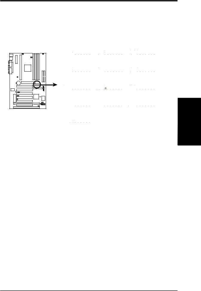
3)CPU Core:BUS Frequency Multiple (DSW-Switches 1-4)
This option sets the frequency multiple between the Internal frequency of the CPU and the CPU’s External frequency. These must be set in conjunction with the
CPU Bus Frequency.
NOTE: In JumperFree™ mode, all dip switches (DSW) must be set to OFF.
P3B-F |
P3B-F CPU : BUS
Frequency Multiple
ON |
|
|
|
|
|
|
|
|
|
|
ON |
|
ON |
||||||||||||||||
|
|
|
|
|
|
|
|
|
|
|
|
|
|
|
|
|
|
|
|
|
|
|
|
|
|
|
|
|
|
|
|
|
|
|
|
|
|
|
|
|
|
|
|
|
|
|
|
|
|
|
|
|
|
|
|
|
|
|
|
1 2 3 4 5 6 7 8 9 10 |
|
1 2 3 4 5 6 7 8 9 10 |
|
1 2 3 4 5 6 7 8 9 10 |
|||||||||||||||||||||||||
|
|
|
2.0x(2/1) |
|
|
|
|
|
2.5x(5/2) |
|
|
|
3.0x(3/1) |
||||||||||||||||
|
|
|
|
|
|
|
|
|
|
|
|
|
|
|
|
|
|
|
|
|
|
|
|
|
|
|
|
|
|
ON |
|
|
|
|
|
|
|
|
|
|
ON |
|
ON |
||||||||||||||||
|
|
|
|
|
|
|
|
|
|
|
|
|
|
|
|
|
|
|
|
|
|
|
|
|
|
|
|
|
|
|
|
|
|
|
|
|
|
|
|
|
|
|
|
|
|
|
|
|
|
|
|
|
|
|
|
|
|
|
|
1 2 3 4 5 6 7 8 9 10 |
|
1 2 3 4 5 6 7 8 9 10 |
|
1 2 3 4 5 6 7 8 9 10 |
|||||||||||||||||||||||||
|
|
|
3.5x(7/2) |
|
|
|
|
|
4.0x(4/1) |
|
|
|
4.5x(9/2) |
||||||||||||||||
|
|
|
|
|
|
|
|
|
|
|
|
|
|
|
|
|
|
|
|
|
|
|
|
|
|
|
|
|
|
ON |
|
|
|
|
|
|
|
|
|
|
ON |
|
ON |
||||||||||||||||
|
|
|
|
|
|
|
|
|
|
|
|
|
|
|
|
|
|
|
|
|
|
|
|
|
|
|
|
|
|
|
|
|
|
|
|
|
|
|
|
|
|
|
|
|
|
|
|
|
|
|
|
|
|
|
|
|
|
|
|
1 2 3 4 5 6 7 8 9 10 |
|
1 2 3 4 5 6 7 8 9 10 |
|
1 2 3 4 5 6 7 8 9 10 |
|||||||||||||||||||||||||
|
|
|
5.0x(5/1) |
|
|
|
|
|
|
5.5x(11/2) |
|
|
|
6.0x(6/1) |
|||||||||||||||
|
|
|
|
|
|
|
|
|
|
|
|
|
|
|
|
|
|
|
|
|
|
|
|
|
|
|
|
|
|
ON |
|
|
|
|
|
|
|
|
|
|
ON |
|
ON |
||||||||||||||||
|
|
|
|
|
|
|
|
|
|
|
|
|
|
|
|
|
|
|
|
|
|
|
|
|
|
|
|
|
|
|
|
|
|
|
|
|
|
|
|
|
|
|
|
|
|
|
|
|
|
|
|
|
|
|
|
|
|
|
|
1 2 3 4 5 6 7 8 9 10 |
|
1 2 3 4 5 6 7 8 9 10 |
|
1 2 3 4 5 6 7 8 9 10 |
|||||||||||||||||||||||||
|
|
6.5x(13/2) |
|
|
|
|
|
7.0x(7/1) |
|
|
7.5x(15/2) |
||||||||||||||||||
|
|
|
|
|
|
|
|
|
|
|
|
|
|
|
|
|
|
|
|
|
|
|
|
|
|
|
|
|
|
ON |
|
|
|
|
|
|
|
|
|
|
|
|
|
|
|
|
|
|
|
|
|
|
|
|
|
|
|
|
|
|
|
|
|
|
|
|
|
|
|
|
|
|
|
|
|
|
|
|
|
|
|
|
|
|
|
|
|
|
|
|
|
|
|
|
|
|
|
|
|
|
|
|
|
|
|
|
|
|
|
|
|
|
|
|
|
|
|
|
|
1 |
2 |
3 |
4 |
5 |
6 |
7 |
8 |
9 10 |
|
|
|
|
|
|
|
|
|
|
|
|
|
|
|
|
|
|
|
||
|
|
|
8.0x(8/1) |
|
|
|
|
|
|
|
|
|
|
|
|
|
|
|
|
|
|
|
|
|
|
||||
Manual CPU Settings
NOTE: JumperFree mode must be disabled .
Set the DIP switches by the Internal speed of your processor as follows:
|
|
|
|
|
|
|
|
|
|
|
|
|
|
|
Intel CPU Model |
Freq. |
|
|
|
|
|
(CPU BUS Freq.) |
(Freq. Multiple) |
(AGP) |
|||||
|
|
|
|
|
||||||||||
Mult. |
Bus |
F. |
7 |
8 |
9 10 |
1 |
2 |
3 |
4 |
6 |
||||
Pentium III |
600MHz |
6.0x |
100MHz |
[OFF][OFF][OFF] [ON] |
[ON] [ON] [ON] [OFF] [OFF] |
|||||||||
Pentium III |
550MHz |
5.5x |
100MHz |
[OFF][OFF][OFF] [ON] |
[OFF][OFF][OFF] [ON] |
[OFF] |
||||||||
Pentium III |
500MHz |
5.0x |
100MHz |
[OFF][OFF][OFF] [ON] |
[ON] [OFF][OFF] [ON] |
[OFF] |
||||||||
Pentium III/II |
450MHz |
4.5x |
100MHz |
[OFF][OFF][OFF] [ON] |
[OFF] [ON] [OFF] [ON] |
[OFF] |
||||||||
Pentium II |
400MHz |
4.0x |
100MHz |
[OFF][OFF][OFF] [ON] |
[ON] [ON] [OFF] [ON] |
[OFF] |
||||||||
Pentium II |
350MHz |
3.5x |
100MHz |
[OFF][OFF][OFF] [ON] |
[OFF][OFF] [ON] [ON] |
[OFF] |
||||||||
Celeron |
500MHz |
7.5x |
66MHz |
[OFF][OFF] [ON] [ON] |
[OFF][OFF] [ON] [OFF] |
[ON] |
||||||||
Celeron |
466MHz |
7.0x |
66MHz |
[OFF][OFF] [ON] [ON] |
[ON] [OFF] [ON] [OFF] |
[ON] |
||||||||
Celeron |
433MHz |
6.5x |
66MHz |
[OFF][OFF] [ON] [ON] |
[OFF] [ON] [ON] [OFF] |
[ON] |
||||||||
Celeron |
400MHz |
6.0x |
66MHz |
[OFF][OFF] [ON] [ON] |
[ON] [ON] [ON] [OFF] |
[ON] |
||||||||
Celeron |
366MHz |
5.5x |
66MHz |
[OFF][OFF] [ON] [ON] |
[OFF][OFF][OFF] [ON] |
[ON] |
||||||||
Pentium II/Celeron |
333MHz |
5.0x |
66MHz |
[OFF][OFF] [ON] [ON] |
[ON] [OFF][OFF] [ON] |
[ON] |
||||||||
Pentium II/Celeron |
300MHz |
4.5x |
66MHz |
[OFF][OFF] [ON] [ON] |
[OFF] [ON] [OFF] [ON] |
[ON] |
||||||||
Pentium II/Celeron |
266MHz |
4.0x |
66MHz |
[OFF][OFF] [ON] [ON] |
[ON] [ON] [OFF] [ON] |
[ON] |
||||||||
Pentium II |
233MHz |
3.5x |
66MHz |
[OFF][OFF] [ON] [ON] |
[OFF][OFF] [ON] [ON] |
[ON] |
||||||||
For updated processor settings, please visit ASUS’ web site (see ASUS CONTACT INFORMATION).
.3 SETUPH/W
Motherboard Settings
ASUS P3B-F User’s Manual |
19 |
Settings Motherboard
.3 SETUP H/W
3.HARDWARE SETUP
4)JumperFreeTM Mode Setting (JEN)
This allows you to enable or disable JumperFreeTM mode. JumperFreeTM mode allows processor settings to be made through BIOS setup.
NOTE: In JumperFreeTM mode, all dip switches (DSW) must be set to OFF.
Setting |
JEN |
Enable (jumperfree) [2-3] (default)
Disable (jumper) |
[1-2] |
|||||||
|
|
|
|
|
|
|
|
|
|
|
|
|
|
|
|
|
|
|
|
|
|
|
|
|
|
|
|
|
|
|
|
|
|
|
|
|
|
|
|
|
|
|
|
|
|
|
|
|
|
|
|
|
|
|
|
|
|
|
|
|
|
|
|
|
|
|
|
|
|
|
|
|
|
|
|
|
|
|
|
|
|
|
|
|
|
|
|
|
|
|
|
|
|
|
|
|
|
|
JEN
1 |
2 |
3 |
1 |
2 |
3 |
P3B-F |
JumperFree |
Jumper |
P3B-F Jumper Mode Setting
NOTE: In JumperFree mode, your system will start up at a bus speed of 66MHz (2.0x frequency multiplier is used for processors with unlocked multiplier) and automatically enter BIOS setup for you to select your processor internal speed after you have changed/reinstalled the processor or after a system hangup due to improper CPU settings (see 4.4 Advanced Menu).
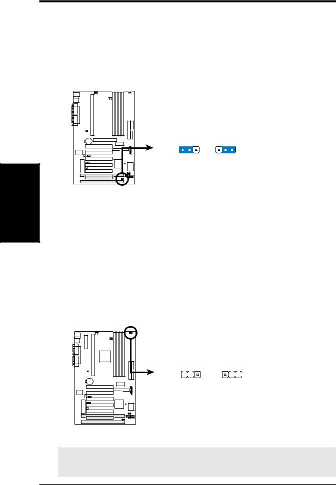
5)I/O Voltage Setting (JP20)
This jumper allows you to select the voltage supplied to the DRAM, chipset, and AGP.
Setting |
JP20 |
|||
3.50 Volt |
[1-2] (default) |
|||
3.65 Volt |
[2-3] |
|||
|
|
|
|
|
|
|
|
|
|
|
|
|
|
|
|
|
|
|
|
|
|
|
|
|
|
|
|
|
|
JP20
(VIO)
|
1 |
2 |
3 |
1 |
2 |
3 |
|||
|
|||||||||
|
|
|
|
|
|
|
|
|
|
|
|
|
|
|
|
|
|
|
|
|
|
|
|
|
|
|
|
|
|
F |
3.50 Volt |
3.65 Volt |
- |
(default) |
|
P3B |
|
P3B-F Input/Output Voltage Setting
WARNING! Using a higher voltage may help when overclocking but may result in the shortening of your computer components’ life. Leave on default setting.
20 |
ASUS P3B-F User’s Manual |
3.HARDWARE SETUP
3.5System Memory (DIMM)
NOTE: No hardware or BIOS setup is required after adding or removing memory.
This motherboard uses only Dual Inline Memory Modules (DIMMs). Sockets are available for 3.3Volt (power level) unbuffered Synchronous Dynamic Random Access Memory (SDRAM). One side (with memory chips) of the DIMM takes up one row on the motherboard.
To utilize the chipset’s Error Checking and Correction (ECC) feature, you must use a DIMM module with 9 chips per side (standard 8 chips/side + 1 ECC chip) and make the proper settings through 4.4.1 Chip Configuration.
Memory speed setup is recommended through SDRAM Configuration in 4.4.1 Chip Configuration.
Install memory in any combination as follows:
DIMM Location |
168-pin DIMM |
|
Total Memory |
Socket 1 (Rows 0&1) |
SDRAM 8, 16, 32, 64, 128, 256MB |
x1 |
|
|
|
|
|
Socket 2 (Rows 2&3) |
SDRAM 8, 16, 32, 64, 128, 256MB |
x1 |
|
|
|
|
|
Socket 3 (Rows 4&5) |
SDRAM 8, 16, 32, 64, 128, 256MB |
x1 |
|
|
|
|
|
Socket 4 (Rows 6&7) |
SDRAM 8, 16, 32, 64, 128, 256MB |
x1 |
|
|
|
|
|
|
Total System Memory (Max 1024MB) |
= |
|
|
|
|
|
NOTE: At the time this User’s Manual was written, 256MB DIMMs are only available as double-sided registered memory.
3.5.1 General DIMM Notes
•For the system CPU bus to operate at 100MHz, use only PC100-compliant DIMMs. When this motherboard operates at 100MHz, most system will not even boot if non-compliant modules are used because of the strict timing issues involved under this speed. If your DIMMs are not PC100-compliant, set the CPU bus frequency to 66MHz RAM to ensure system stability.
•ASUS motherboards support SPD (Serial Presence Detect) DIMMs. This is the memory of choice for best performance vs. stability.
•Two possible memory chips are supported: SDRAM with and without ECC.
•SDRAM chips are generally thinner with higher pin density than EDO (Extended Data Output) chips.
•BIOS shows SDRAM memory on bootup screen.
•Single-sided DIMMs come in 16, 32, 64,128MB; double-sided come in 32, 64, 128, 256MB.
System Memory
3. H/W SETUP
ASUS P3B-F User’s Manual |
21 |
3.HARDWARE SETUP
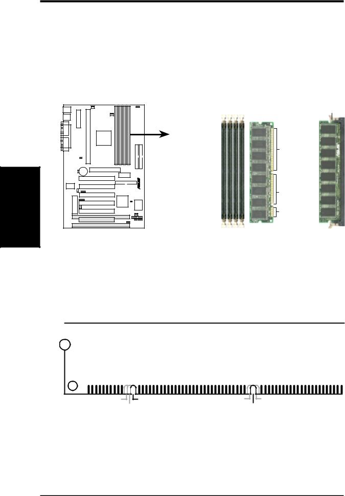
3.5.2DIMM Memory Installation
Insert the module(s) as shown. Because the number of pins are different on either side of the breaks, the module will only fit in the orientation shown. DRAM SIMM modules have the same pin contacts on both sides. SDRAM DIMMs have different pin contacts on each side and therefore have a higher pin density.
Memory System
3.H/W |
P3B-F |
SETUP |
|
P3B-F 168-Pin DIMM Memory Sockets
Lock
88 Pins
60 Pins
20 Pins
The DIMMs must be 3.3Volt unbuffered SDRAMs. To determine the DIMM type, check the notches on the DIMMs (see figure below).
168-Pin DIMM Notch Key Definitions (3.3V)
|
|
|
|
|
|
|
|
|
|
|
|
|
|
|
|
|
|
|
|
|
|
|
|
|
|
|
|
|
|
DRAM Key Position |
Voltage Key Position |
|||
RFU |
Unbuffered |
5.0V |
Reserved |
Buffered |
|
3.3V |
|
The notches on the DIMM will shift between left, center, or right to identify the type and also to prevent the wrong type from being inserted into the DIMM slot on the motherboard. You must tell your retailer the correct DIMM type before purchasing. This motherboard supports four clock signals per DIMM.
22 |
ASUS P3B-F User’s Manual |
3.HARDWARE SETUP
3.6Central Processing Unit (CPU)
NOTE: The following pictures are provided for reference purposes only. The appearance of your retention mechanism and fan may be different from the following examples.
Your motherboard provides a Slot 1 connector for a Pentium® III processor packaged in a Single Edge Contact Cartridge (SECC2), a Pentium® II processor packaged in SECC2/SECC, or a Celeron™ processor packaged in a Single Edge Processor Package (SEPP). An ASUS S370 CPU card can allow Socket 370 processors to be used on any ASUS motherboard with the Slot 1 connector (See 7.2 ASUS S370 Series CPU Cards for instructions on using this card).
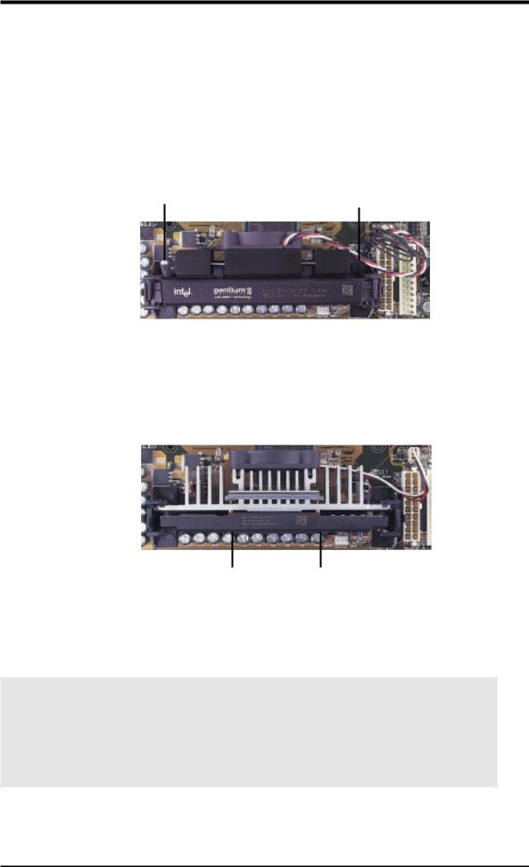
Pentium II processor packaged in an SECC with |
Pentium III (in an SECC2) with heatsink and fan |
heatsink and fan (top view) |
NOTE: The SEPP fan (for Celeron processors) is |
|
similar to SECC2 fan except that the clamping |
|
design is different. |
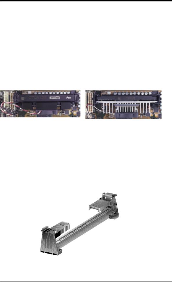
3.6.1 Universal Retention Mechanism
Your motherboard comes preinstalled with a Universal Retention Mechanism (URM). The URM supports Pentium III / II and Celeron processors.
Universal Retention Mechanism (URM)
H/WSETUP |
CPU |
3. |
|
|
|
ASUS P3B-F User’s Manual |
23 |
.3 SETUP H/WCPU
3.HARDWARE SETUP
3.6.2Heatsinks
The recommended heatsinks (see 3.6.4 Recommended Heatsinks for Slot 1 Processors for more information) for the boxed Pentium III / II and Celeron processors are those with three-pin fans that can be connected to the fan connectors on the motherboard.
WARNING! Be sure that there is sufficient air circulation across the processor’s heatsink by regularly checking that your CPU fan is working. Without sufficient circulation, the processor could overheat and damage both the processor and the motherboard. You may install an auxiliary chassis fan, if necessary.
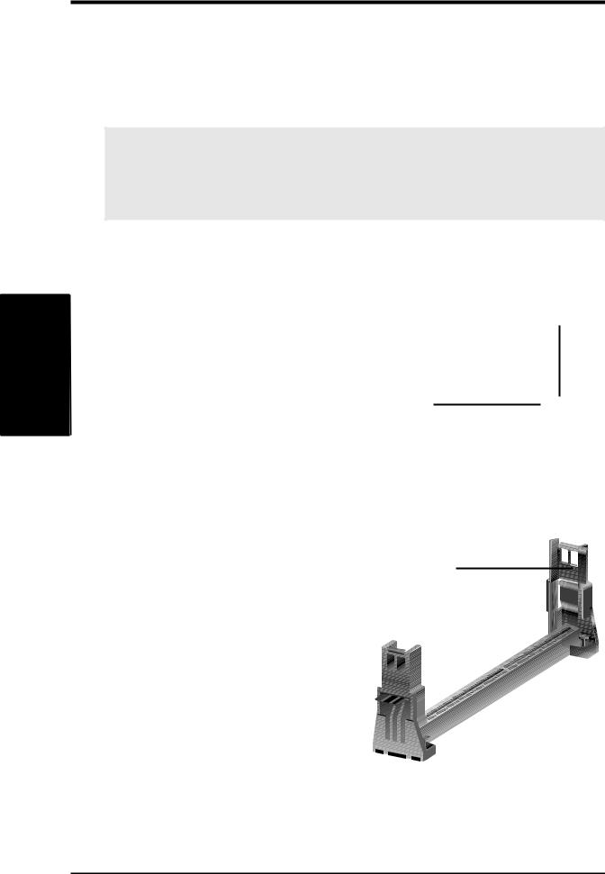
3.6.3 Installing the Processor
1.Unlock the URM’s Folding Support Arms: The folding support arms of the URM are locked when shipped.
Locked Folding
Support Arms
To unlock the support arms, simply flip |
Unlocked Folding |
|
them up to an upright position. |
||
Support Arms |
||
|
|
|
|
|
|
|
|
|
|
|
|
|
|
|
|
|
|
|
|
The URM is now ready for the installation of your processor.
24 |
ASUS P3B-F User’s Manual |
3.HARDWARE SETUP
2.Attach the Heatsink
NOTE: If provided, you should follow the heatsink attachment instructions that came with your heatsink or processor. The following steps are provided only as a general guide and may not reflect those for your heatsink.
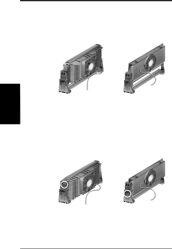
Using the SECC fan with the Pentium® II
Push the two lock arms one direction to clamp the heatsink onto the processor and the other direction to release.
Lock Arm Lock Arm
Using the SECC2 fan with the Pentium® III
Insert the four heatsink’s pins through the holes of the SECC2. Place the metal clip on the ends of the pins and slide until it locks into place.
H/WSETUP |
CPU |
3. |
|
|
|
Four Pins and metal clip
NOTE: The SEPP heatsink and fan (for Intel Celeron processors) is similar to the SECC2 heatsink and fan except that the clamping design is different.
WARNING! Make sure the heatsink is mounted tightly against the SECC2, SECC, or SEPP; otherwise, the CPU will overheat. Inspect visually to make sure that there is no gap between the processor die and the heatsink and that the heatsink is parallel to the processor. You may install an auxiliary fan to provide adequate circulation across the processor’s passive heatsink.
ASUS P3B-F User’s Manual |
25 |
.3 SETUP H/WCPU
3.HARDWARE SETUP
3.Insert the SECC2/SECC/SEPP
SECC with Pentium® II only: Push the SECC’s two locks inward until you hear a click (the picture in step 2 shows the locks in the outward position and inward in the picture below).
With the heatsink facing the motherboard’s chipset, push the SECC2, SECC, or SEPP gently but firmly into the Slot 1 connector until it is fully inserted.
SECC |
SECC2/SEPP |
Push lock inward 


CPU fan cable to |
CPU fan cable to |
fan connector |
fan connector |
4.Secure the SECC2/SECC/SEPP
Secure the SECC2/SECC/SEPP in place by pushing the SECC2/SECC/SEPP until it is firmly seated on the Slot 1 connector.
SECC with Pentium® II only: The SECC locks should be outward when secured so that the lock shows through the retention mechanism’s lock holes.
SECC |
SECC2/SEPP |
Lock hole |
|
|
|
Lock hole |
CPU fan |
|
|
|
CPU fan cable to |
|
cable to fan |
fan connector |
|
connector |
26 |
ASUS P3B-F User’s Manual |
3.HARDWARE SETUP
3.6.4Recommended Heatsinks for Slot 1 Processors
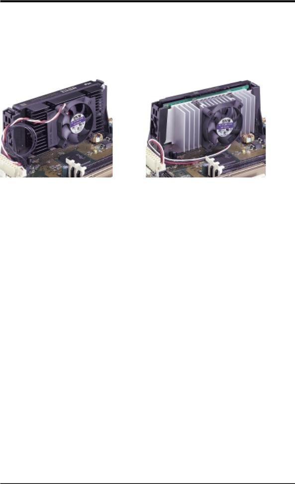
The recommended heatsinks for the Slot 1 processors are those with three-pin fans, such as the ASUS Smart Fan, that can be connected to the motherboard’s CPU fan connector. These heatsinks dissipate heat more efficiently and with an optional hardware monitor, they can monitor the fan’s RPM and use the alert function with the Intel LANDesk Client Manager (LDCM) or the ASUS PC Probe software.
SECC Heatsink & Fan |
SECC2 Heatsink & Fan |
NOTE: The SEPP heatsink and fan (for Intel Celeron processors) is similar to the SECC2 heatsink and fan except that the clamping design is different.
H/WSETUP |
CPU |
3. |
|
|
|
ASUS P3B-F User’s Manual |
27 |
.3 SETUP H/WCPU
3.HARDWARE SETUP
3.6.5Precautions
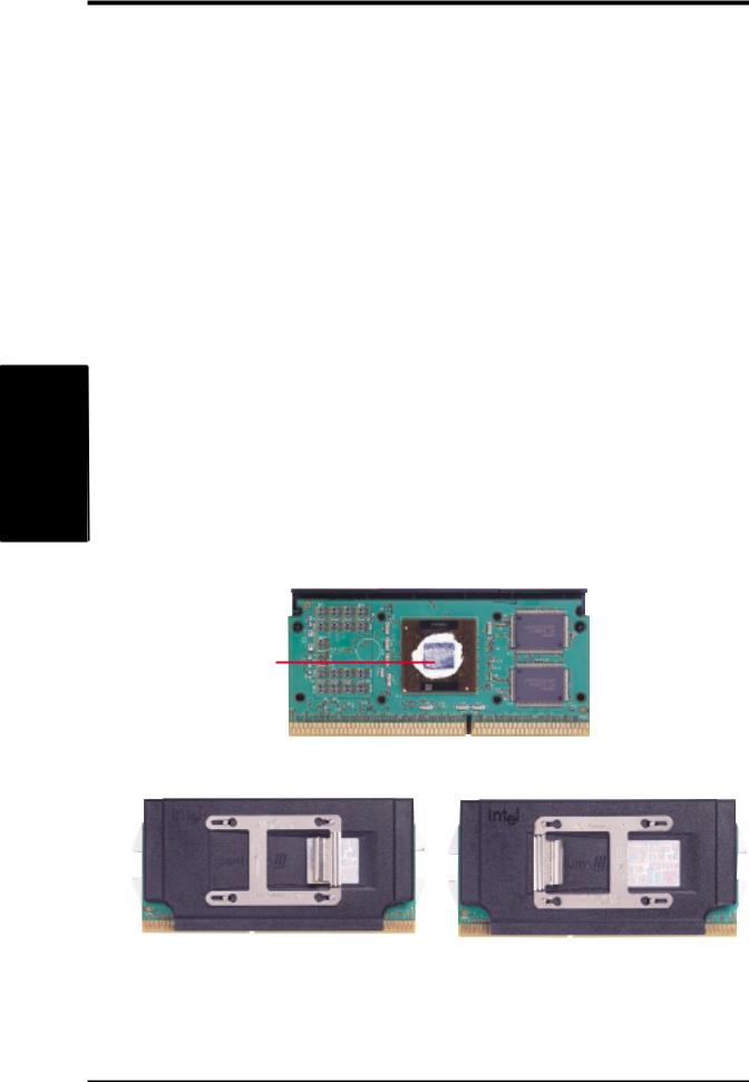
Operating a processor at temperatures above its maximum specified operating temperature will shorten the processor lifetime and may cause unreliable operation. To prevent system overheat and/or damage, it is important to have accurate temperature readings of the processor core (the main source of power dissipation) for system thermal management. Included inside Pentium III, Pentium II (Deschutes), and PPGA370 Celeron processors is a thermal sensor that is connected to the internal thermal diode.
Unlike other motherboards, this motherboard was designed to acquire thermal data directly from the processor thermal diode. Therefore, the CPU temperature reported may be higher than those from motherboards that take readings from thermal sensors external to the processor. This is not a cause for alarm. If, however, the BIOS and/or your hardware monitoring program is reporting a CPU temperature above the threshold, check the following:
1.An Intel recommended fan heatsink is used.
2.Good quality thermal interface material is used.
3.The heatsink is correctly installed onto the processor with a strong retention clip.
4.There is no visible gap between the processor die and heatsink.
The thermal interface material should be continuous with no through-holes or debris.
Example of a correctly installed retention clip |
Example of an incorrectly installed retention clip |
28 |
ASUS P3B-F User’s Manual |

3.HARDWARE SETUP
3.7Expansion Cards
WARNING! Unplug your power supply when adding or removing expansion cards or other system components. Failure to do so may cause severe damage to both your motherboard and expansion cards.
3.7.1 Expansion Card Installation Procedure
1.Read the documentation for your expansion card and make any necessary hardware or software settings for your expansion card, such as jumpers.
2.Remove your computer system’s cover and the bracket plate on the slot you intend to use. Keep the bracket for possible future use.
3.Carefully align the card’s connectors and press firmly.
4.Secure the card on the slot with the screw you removed above.
5.Replace the computer system’s cover.
6.Set up the BIOS if necessary
(such as IRQ xx Used By ISA: Yes in 4.4.3 PCI Configuration)
7.Install the necessary software drivers for your expansion card.
3.7.2 Assigning IRQs for Expansion Cards
Some expansion cards need an IRQ to operate. Generally, an IRQ must be exclusively assigned to one use. In a standard design, there are 16 IRQs available but most of them are already in use, leaving 6 IRQs free for expansion cards. If your motherboard has PCI audio onboard, an additional IRQ will be used. If your motherboard also has MIDI enabled, another IRQ will be used, leaving 4 IRQs free.
IMPORTANT: If using PCI cards on shared slots, make sure that the drivers support “Share IRQ” or that the cards do not need IRQ assignments. Conflicts will arise between the two PCI groups that will make the system unstable or cards inoperable.
Interrupt Request Table
|
INT-A |
INT-B |
INT-C |
INT-D |
PCI slot 1 |
shared |
-- |
-- |
-- |
PCI slot 2 |
-- |
shared |
-- |
-- |
PCI slot 3 |
-- |
-- |
shared |
-- |
PCI slot 4 |
-- |
-- |
-- |
shared |
PCI slot 5 |
-- |
-- |
-- |
shared |
PCI slot 6 |
-- |
-- |
shared |
-- |
AGP |
shared |
---- |
-- |
-- |
USB |
-- |
-- |
-- |
shared |
Expansion Cards
3. H/W SETUP
ASUS P3B-F User’s Manual |
29 |

SETUP H/W .3
Cards Expansion
3. HARDWARE SETUP
The following table lists the default IRQ assignments for standard PC devices. Use this table when configuring your system and for resolving IRQ conflicts.
Standard Interrupt Assignments
IRQ |
Priority |
Standard Function |
0 |
1 |
System Timer |
1 |
2 |
Keyboard Controller |
2 |
N/A |
Programmable Interrupt |
3* |
11 |
Communications Port (COM2) |
4* |
12 |
Communications Port (COM1) |
5* |
13 |
|
6 |
14 |
Floppy Disk Controller |
7* |
15 |
Printer Port (LPT1) |
8 |
3 |
System CMOS/Real Time Clock |
9* |
4 |
ACPI Mode when used |
10* |
5 |
IRQ Holder for PCI Steering |
11* |
6 |
IRQ Holder for PCI Steering |
12* |
7 |
PS/2 Compatible Mouse Port |
13 |
8 |
Numeric Data Processor |
14* |
9 |
Primary IDE Channel |
15* |
10 |
Secondary IDE Channel |
*These IRQs are usually available for ISA or PCI devices.
Both ISA and PCI expansion cards may require IRQs. System IRQs are available to cards installed in the ISA expansion bus first, then any remaining IRQs are available to PCI cards. Currently, there are two types of ISA cards.
The original ISA expansion card design, now referred to as “Legacy” ISA cards, requires that you configure the card’s jumpers manually and then install it in any available slot on the ISA bus. To see a map of your used and free IRQs in Windows 98, the Control Panel icon in My Computer, contains a System icon, which gives you a Device Manager tab. Double-clicking on a specific hardware device gives you the Resources tab which shows the Interrupt number and address. Double-click Computer to see all the interrupts and addresses for your system. Make sure that no two devices use the same IRQ or your computer will experience problems when those two devices are in use at the same time.
30 |
ASUS P3B-F User’s Manual |
 Loading...