


|
Motherboard |
M4A88T-V EVO/USB3 |
|
M4A88T-V EVO |
|

E5927
First Edition (V1)
July 2010
Copyright © 2010 ASUSTeK Computer Inc. All Rights Reserved.
No part of this manual, including the products and software described in it, may be reproduced, transmitted, transcribed, stored in a retrieval system, or translated into any language in any form or by any means, except documentation kept by the purchaser for backup purposes, without the express written permission of ASUSTeK Computer Inc. (“ASUS”).
Product warranty or service will not be extended if: (1) the product is repaired, modified or altered, unless such repair, modification of alteration is authorized in writing byASUS; or (2) the serial number of the product is defaced or missing.
ASUS PROVIDES THIS MANUAL “AS IS” WITHOUT WARRANTY OF ANY KIND, EITHER EXPRESS OR IMPLIED, INCLUDING BUT NOT LIMITED TO THE IMPLIED WARRANTIES OR CONDITIONS OF MERCHANTABILITY OR FITNESS FOR A PARTICULAR PURPOSE. IN NO EVENT SHALL ASUS, ITS DIRECTORS, OFFICERS, EMPLOYEES OR AGENTS BE LIABLE FOR ANY INDIRECT, SPECIAL, INCIDENTAL, OR CONSEQUENTIAL DAMAGES (INCLUDING DAMAGES FOR LOSS OF PROFITS, LOSS OF BUSINESS, LOSS OF USE OR DATA, INTERRUPTION OF BUSINESS AND THE LIKE), EVEN IF ASUS HAS BEEN ADVISED OF THE POSSIBILITY OF SUCH DAMAGES ARISING FROM ANY DEFECT OR ERROR IN THIS MANUAL OR PRODUCT.
SPECIFICATIONS AND INFORMATION CONTAINED IN THIS MANUAL ARE FURNISHED FOR INFORMATIONAL USE ONLY, AND ARE SUBJECT TO CHANGE AT ANY TIME WITHOUT NOTICE, AND SHOULD NOT BE CONSTRUED AS A COMMITMENT BY ASUS. ASUS ASSUMES NO RESPONSIBILITY OR LIABILITY FOR ANY ERRORS OR INACCURACIES THAT MAY APPEAR IN THIS MANUAL, INCLUDING THE PRODUCTS AND SOFTWARE DESCRIBED IN IT.
Products and corporate names appearing in this manual may or may not be registered trademarks or copyrights of their respective companies, and are used only for identification or explanation and to the owners’ benefit, without intent to infringe.
Offer to Provide Source Code of Certain Software
This product may contain copyrighted software that is licensed under the General Public License (“GPL”) and under the Lesser General Public License Version (“LGPL”). The GPL and LGPL licensed code in this product is distributed without any warranty. Copies of these licenses are included in this product.
You may obtain the complete corresponding source code (as defined in the GPL) for the GPL Software, and/or the complete corresponding source code of the LGPL Software (with the complete machinereadable “work that uses the Library”) for a period of three years after our last shipment of the product including the GPL Software and/or LGPL Software, which will be no earlier than December 1, 2011, either
(1)for free by downloading it from http://support.asus.com/download;
or
(2)for the cost of reproduction and shipment, which is dependent on the preferred carrier and the location where you want to have it shipped to, by sending a request to:
ASUSTeK Computer Inc.
Legal Compliance Dept.
15 Li Te Rd.,
Beitou, Taipei 112
Taiwan
In your request please provide the name, model number and version, as stated in the About Box of the product for which you wish to obtain the corresponding source code and your contact details so that we can coordinate the terms and cost of shipment with you.
The source code will be distributed WITHOUT ANY WARRANTY and licensed under the same license as the corresponding binary/object code.
This offer is valid to anyone in receipt of this information.
ASUSTeK is eager to duly provide complete source code as required under various Free Open Source Software licenses. If however you encounter any problems in obtaining the full corresponding source code we would be much obliged if you give us a notification to the email address gpl@asus.com, stating the product and describing the problem (please do NOT send large attachments such as source code archives etc to this email address).
ii

Contents
Notices......................................................................................................... |
vi |
Safety information...................................................................................... |
vii |
About this guide......................................................................................... |
vii |
M4A88T-V EVO Series specifications summary....................................... |
ix |
Chapter 1: |
Product introduction |
|
|
1.1 |
Welcome!....................................................................................... |
1-1 |
|
1.2 |
Package contents......................................................................... |
1-1 |
|
1.3 |
Special features............................................................................ |
1-1 |
|
|
1.3.1 |
Product highlights ............................................................ |
1-1 |
|
1.3.2 |
Innovative ASUS features ................................................ |
1-3 |
1.4 |
Before you proceed...................................................................... |
1-6 |
|
1.5 |
Motherboard overview................................................................. |
1-7 |
|
|
1.5.1 |
Placement direction ......................................................... |
1-7 |
|
1.5.2 |
Screw holes ..................................................................... |
1-7 |
|
1.5.3 |
Motherboard layout .......................................................... |
1-7 |
|
1.5.4 |
Layout contents . .............................................................. |
1-8 |
1.6 |
Central Processing Unit (CPU).................................................... |
1-9 |
|
|
1.6.1 |
Installing the CPU ............................................................ |
1-9 |
|
1.6.2 |
Installing the heatsink and fan ........................................ |
1-11 |
1.7 |
System memory.......................................................................... |
1-12 |
|
|
1.7.1 |
Overview ........................................................................ |
1-12 |
|
1.7.2 |
Memory configurations . ................................................. |
1-13 |
|
1.7.3 |
Installing a DIMM ........................................................... |
1-18 |
|
1.7.4 |
Removing a DIMM ......................................................... |
1-18 |
1.8 |
Expansion slots.......................................................................... |
1-19 |
|
|
1.8.1 |
Installing an expansion card .......................................... |
1-19 |
|
1.8.2 |
Configuring an expansion card ...................................... |
1-19 |
|
1.8.3 |
PCI slots . ....................................................................... |
1-19 |
|
1.8.4 |
PCI Express x1 slot . ...................................................... |
1-19 |
|
1.8.5 |
PCI Express x16 slots ................................................... |
1-19 |
1.9 |
Jumpers |
....................................................................................... |
1-20 |
1.10 |
Connectors.................................................................................. |
1-21 |
|
|
1.10.1 ............................................................ |
Rear panel ports |
1-21 |
|
1.10.2 ........................................................ |
Internal connectors |
1-24 |
1.11 |
Onboard .......................................................................switches |
1-32 |
|
1.12 |
Onboard .............................................................................LEDs |
1-35 |
|
iii

Contents
1.13 Software support........................................................................ |
1-37 |
|
1.13.1 |
Installing an operating system....................................... |
1-37 |
1.13.2 |
Support DVD information............................................... |
1-37 |
Chapter 2: |
BIOS information |
|
|
2.1 |
Managing and updating your BIOS............................................. |
2-1 |
|
|
2.1.1 |
ASUS Update utility......................................................... |
2-1 |
|
2.1.2 |
ASUS EZ Flash 2............................................................ |
2-2 |
|
2.1.3 |
ASUS CrashFree BIOS 3................................................ |
2-3 |
|
2.1.4 |
ASUS BIOS Updater....................................................... |
2-4 |
2.2 |
BIOS setup program..................................................................... |
2-7 |
|
|
2.2.1 |
BIOS menu screen.......................................................... |
2-8 |
|
2.2.2 |
Menu bar......................................................................... |
2-8 |
|
2.2.3 |
Navigation keys............................................................... |
2-8 |
|
2.2.4 |
Menu items...................................................................... |
2-9 |
|
2.2.5 |
Submenu items................................................................ |
2-9 |
|
2.2.6 |
Configuration fields.......................................................... |
2-9 |
|
2.2.7 |
Pop-up window................................................................ |
2-9 |
|
2.2.8 |
Scroll bar......................................................................... |
2-9 |
|
2.2.9 |
General help.................................................................... |
2-9 |
2.3 |
Main menu................................................................................... |
2-10 |
|
|
2.3.1 |
System Time.................................................................. |
2-10 |
|
2.3.2 |
System Date.................................................................. |
2-10 |
|
2.3.3 |
Primary IDE Master/Slave, SATA 1/2/3/5/6, E-SATA..... |
2-10 |
|
2.3.4 |
SATAConfiguration......................................................... |
2-11 |
|
2.3.5 |
System Information........................................................ |
2-12 |
2.4 |
Ai Tweaker menu........................................................................ |
2-13 |
|
|
2.4.1 |
CPU Level UP................................................................ |
2-13 |
|
2.4.2 |
CPU OverClocking........................................................ |
2-14 |
|
2.4.3 |
CPU Ratio...................................................................... |
2-15 |
|
2.4.4 |
DRAM Frequency.......................................................... |
2-15 |
|
2.4.5 |
CPU/NB Frequency....................................................... |
2-15 |
|
2.4.6 |
HT Link Speed............................................................... |
2-15 |
|
2.4.7 |
GPU Booster................................................................. |
2-15 |
|
2.4.8 |
OC Tuner Utility............................................................. |
2-16 |
|
2.4.9 |
DRAM Timing Configuration.......................................... |
2-16 |
iv
Contents
|
2.4.10 |
DRAM Driving Configuration......................................... |
2-17 |
|
2.4.11 |
CPU & NB Voltage Mode............................................... |
2-17 |
|
2.4.12 |
CPU VDDA Voltage....................................................... |
2-18 |
|
2.4.13 |
DRAM Voltage............................................................... |
2-18 |
|
2.4.14 |
HT Voltage..................................................................... |
2-18 |
|
2.4.15 |
NB Voltage..................................................................... |
2-18 |
|
2.4.16 |
NB 1.8V Voltage............................................................ |
2-18 |
|
2.4.17 |
SB Voltage..................................................................... |
2-18 |
|
2.4.18 |
SidePort Memory Voltage.............................................. |
2-18 |
|
2.4.19 |
CPU Load-Line Calibration............................................ |
2-18 |
|
2.4.20 |
CPU/NB Load-Line Calibration...................................... |
2-18 |
|
2.4.21 |
PCI/PCIe CLK Status.................................................... |
2-19 |
2.5 |
Advanced menu.......................................................................... |
2-19 |
|
|
2.5.1 |
CPU Configuration......................................................... |
2-19 |
|
2.5.2 |
Chipset.......................................................................... |
2-20 |
|
2.5.3 |
Onboard Devices Configuration.................................... |
2-22 |
|
2.5.4 |
PCIPnP.......................................................................... |
2-23 |
|
2.5.5 |
USB Configuration......................................................... |
2-23 |
2.6 |
Power menu................................................................................ |
2-24 |
|
|
2.6.1 |
Suspend Mode.............................................................. |
2-24 |
|
2.6.2 |
ACPI 2.0 Support........................................................... |
2-24 |
|
2.6.3 |
ACPI APIC Support....................................................... |
2-24 |
|
2.6.4 |
APM Configuration........................................................ |
2-24 |
|
2.6.5 |
HW Monitor Configuration............................................. |
2-25 |
|
2.6.6 |
Anti Surge Support........................................................ |
2-26 |
|
2.6.7 |
NB Thermal Protect....................................................... |
2-26 |
2.7 |
Boot menu................................................................................... |
2-27 |
|
|
2.7.1 |
Boot Device Priority....................................................... |
2-27 |
|
2.7.2 |
Boot Settings Configuration........................................... |
2-27 |
|
2.7.3 |
Security.......................................................................... |
2-28 |
2.8 |
Tools menu.................................................................................. |
2-29 |
|
|
2.8.1 |
ASUS EZ Flash 2.......................................................... |
2-29 |
|
2.8.2 |
Express Gate................................................................. |
2-30 |
|
2.8.3 |
ASUS O.C. Profile......................................................... |
2-30 |
|
2.8.4 |
AI NET 2........................................................................ |
2-31 |
2.9 |
Exit menu..................................................................................... |
2-31 |
|
|
|
|
|
Notices
Federal Communications Commission Statement
This device complies with Part 15 of the FCC Rules. Operation is subject to the following two conditions:
•This device may not cause harmful interference, and
•This device must accept any interference received including interference that may cause undesired operation.
This equipment has been tested and found to comply with the limits for a Class B digital device, pursuant to Part 15 of the FCC Rules. These limits are designed to provide reasonable protection against harmful interference in a residential installation. This equipment generates, uses and can radiate radio frequency energy and, if not installed and used in accordance with manufacturer’s instructions, may cause harmful interference to radio communications. However, there is no guarantee that interference will not occur in a particular installation. If this equipment does cause harmful interference to radio or
television reception, which can be determined by turning the equipment off and on, the user is encouraged to try to correct the interference by one or more of the following measures:
•Reorient or relocate the receiving antenna.
•Increase the separation between the equipment and receiver.
•Connect the equipment to an outlet on a circuit different from that to which the receiver is connected.
•Consult the dealer or an experienced radio/TV technician for help.
The use of shielded cables for connection of the monitor to the graphics card is required to assure compliance with FCC regulations. Changes or modifications to this unit not expressly approved by the party responsible for compliance could void the user’s authority to operate this equipment.
Canadian Department of Communications Statement
This digital apparatus does not exceed the Class B limits for radio noise emissions from digital apparatus set out in the Radio Interference Regulations of the Canadian Department of Communications.
This class B digital apparatus complies with Canadian ICES-003.
REACH
Complying with the REACH (Registration, Evaluation, Authorisation, and Restriction of Chemicals) regulatory framework, we published the chemical substances in our products at ASUS REACH website at http://csr.asus.com/english/REACH.htm.
DO NOT throw the motherboard in municipal waste. This product has been designed to enable proper reuse of parts and recycling. This symbol of the crossed out wheeled bin indicates that the product (electrical and electronic equipment) should not be placed in municipal waste. Check local regulations for disposal of electronic products.
DO NOT throw the mercury-containing button cell battery in municipal waste. This symbol of the crossed out wheeled bin indicates that the battery should not be placed in municipal waste.
vi

Safety information
Electrical safety
•To prevent electric shock hazard, disconnect the power cable from the electric outlet before relocating the system.
•When adding or removing devices to or from the system, ensure that the power cables for the devices are unplugged before the signal cables are connected. If possible, disconnect all power cables from the existing system before you add a device.
•Before connecting or removing signal cables from the motherboard, ensure that all power cables are unplugged.
•Seek professional assistance before using an adapter or extension cord. These devices could interrupt the grounding circuit.
•Ensure that your power supply is set to the correct voltage in your area. If you are not sure about the voltage of the electrical outlet you are using, contact your local power company.
•If the power supply is broken, do not try to fix it by yourself. Contact a qualified service technician or your retailer.
Operation safety
•Before installing the motherboard and adding devices on it, carefully read all the manuals that came with the package.
•Before using the product, ensure that all cables are correctly connected and the power cables are not damaged. If you detect any damage, contact your dealer immediately.
•To avoid short circuits, keep paper clips, screws, and staples away from connectors, slots, sockets and circuitry.
•Avoid dust, humidity, and temperature extremes. Do not place the product in any area where it may become wet.
•Place the product on a stable surface.
•If you encounter technical problems with the product, contact a qualified service technician or your retailer.
About this guide
This user guide contains the information you need when installing and configuring the motherboard.
How this guide is organized
This guide contains the following parts:
•Chapter 1: Product introduction
This chapter describes the features of the motherboard and the new technology it supports.
•Chapter 2: BIOS information
This chapter tells how to change system settings through the BIOS Setup menus. Detailed descriptions of the BIOS parameters are also provided.
vii
Conventions used in this guide
To ensure that you perform certain tasks properly, take note of the following symbols used throughout this manual.
DANGER/WARNING: Information to prevent injury to yourself when trying to complete a task.
CAUTION: Information to prevent damage to the components when trying to complete a task.
IMPORTANT: Instructions that you MUST follow to complete a task.
NOTE: Tips and additional information to help you complete a task.
Where to find more information
Refer to the following sources for additional information and for product and software updates.
1.ASUS websites
The ASUS website provides updated information on ASUS hardware and software products. Refer to the ASUS contact information.
2.Optional documentation
Your product package may include optional documentation, such as warranty flyers, that may have been added by your dealer. These documents are not part of the standard package.
Typography
Bold text |
Indicates a menu or an item to select. |
Italics |
Used to emphasize a word or a phrase. |
<Key> |
Keys enclosed in the less-than and greater-than sign means |
|
that you must press the enclosed key. |
|
Example: <Enter> means that you must press the Enter or |
|
Return key. |
<Key1>+<Key2>+<Key3> |
If you must press two or more keys simultaneously, the key |
|
names are linked with a plus sign (+). |
|
Example: <Ctrl>+<Alt>+<D> |
viii

M4A88T-V EVO Series specifications summary
CPU |
AMD® Socket AM3 for AMD® Phenom™ II / Athlon™ II / |
|
Sempron™ 100 series processors |
|
Supports 45nm CPU |
|
AMD® 140W CPU support |
|
AMD® Cool ‘n’ Quiet™ Technology |
|
* Refer to www.asus.com for the AMD® CPU support list |
Chipset
System Bus
Memory
AMD® 880G / SB710
Up to 5200MT/s; HyperTransport™ 3.0 interface
Dual-channel memory architecture
4 x DIMM, max. 16GB, DDR3 2000(O.C.)/1333/1066MHz,
ECC, non-ECC, unbuffered memory*
* AMD® AM3 100 and 200 series CPUs support up to DDR3
1066MHz.
** Refer to www.asus.com for the latest Memory QVL (Qualified
Vendors List).
*** When you install a total memory of 4GB or more, Windows®
32-bit operating system may only recognize less than 3GB. We recommend a maximum of 3GB system memory if you are using a Windows® 32-bit operating system.
Graphics |
Integrated ATI Radeon™ HD 4250 GPU |
|
|
Dual independent displays support: |
|
|
|
• HDMI and D-Sub |
|
|
• DVI and D-Sub |
|
Supports HDMI™ with max. resolution up to 1920x1080 |
|
|
Supports Dual-link DVI with max. resolution up to 2560x1600 @60Hz |
|
|
Supports D-Sub with max. resolution up to 2048x1536 @85Hz |
|
|
Supports Microsoft® DirectX 10.1, OpenGL 2.0, and Shader |
|
|
|
Model 4.1, Universal Video Decoder (UVD) 2.0 |
|
Hardware Decode Acceleration for H.264, VC-1, and MPEG-2 |
|
|
Maximum shared memory of 1GB |
|
|
Supports CrossFireX™* and Hybrid CrossFireX™** |
|
|
* |
For M4A88T-V EVO/USB3, the PCIe x1 slot shares the |
|
|
bandwidth with the PCIe x16_2 slot. Due to the CrossFireX™ |
|
|
limitation, DO NOT use the PCIe x1 slot when you install two |
|
|
CrossFireX™ graphics cards on both the PCIe x16 slots to set up |
|
|
a CrossFireX™ configuration. To disable the PCIe X1 slot, refer |
|
** |
to the NorthBridge Configuration section in the BIOS for details. |
|
Refer to www.amd.com for the discrete GPUs which support |
|
|
|
Hybrid CrossFireX™. |
Integrated memory
Expansion slots
SidePort Memory - onboard 128MB DDR3 1333MHz memory
2 x PCIe 2.0 x16 slots with ATI® CrossFireX™ support
(blue @ x16 mode, gray @ x4 mode)
1 x PCIe 2.0 x1 slot
3 x PCI slots
LAN |
Realtek® 8111E Gigabit LAN controller featuring AI NET 2 |
(continued on the next page)
ix

M4A88T-V EVO Series specifications summary
Storage / RAID |
AMD® SB710 southbridge: |
|
|
- 5 x Serial ATA 3Gb/s connectors support RAID 0, RAID 1, |
|
|
RAID 10, and JBOD configurations |
|
|
- 1 x eSATA port (3Gb/s ready) |
|
|
- 1 x Ultra DMA 133/100/66 connector for up to 2 PATA |
|
|
devices |
|
Audio |
ALC892 8-channel High DefinitionAudio CODEC |
|
|
- Supports 192khz/24bit BD Lossless Sound |
|
|
- Supports Jack-detection, Multi-streaming, and Front Panel |
|
|
Jack-Retasking (HD mode only) |
|
|
- ASUS Noise Filter |
|
|
- Optical S/PDIF Out port at back I/O |
|
USB
IEEE 1394
ASUS unique features
M4A88T-V EVO/USB3:
-2 x USB 3.0 ports (at the back panel)
-10 USB 2.0 ports (6 ports at the mid-board, 4 ports at the back panel)
M4A88T-V EVO:
-12 USB 2.0 ports (6 ports at the mid-board, 6 ports at the back panel)
VIA® VT6308P controller supports 2 IEEE 1394a ports (1 at the mid-board, 1 at the back panel)
ASUS Xtreme Design
ASUS Hybrid Processor - TurboV EVO
- Turbo Unlocker, TurboV, Auto Tuning, CPU Level UP
and GPU Boost
ASUS Hybrid OS - Express Gate
ASUS Hybrid Switches
- Core Unlocker
- Turbo Key II
ASUS Power Solutions
- 8+1 Phase Power Design
- ASUS Anti-Surge Protection
- ASUS EPU
ASUS Exclusive Features
- MemOK!
ASUS Quiet Thermal Solutions
- ASUS Fanless Design: Stylish heat sink solution - ASUS Fan Xpert
ASUS EZ DIY
- ASUS O.C. Profile
- ASUS CrashFree BIOS 3
- ASUS EZ Flash 2
- ASUS MyLogo 2™
(continued on the next page)
M4A88T-V EVO Series specifications summary
ASUS exclusive |
Intelligent overclocking tools: |
||
overclocking |
- |
TurboV EVO |
|
features |
- |
GPU Boost |
|
|
- |
Turbo Key II |
|
|
Precision Tweaker 2 |
||
|
- vCore: Adjustable CPU voltage at 0.003125V increment |
||
|
- vChipset (VDDNB): Adjustable chipset voltage at |
||
|
|
0.01V increment |
|
|
- vDIMM: Adjustable DRAM voltage at 0.015V increment |
||
|
SFS (Stepless Frequency Selection): |
||
|
- HT frequency tuning from 100MHz up to 550MHz at |
||
|
|
1MHz increment |
|
|
- PCIe frequency tuning from 100MHz up to 150MHz at |
||
|
|
1MHz increment |
|
|
Overclocking protection: |
||
|
- ASUS C.P.R. (CPU Parameter Recall) |
|
|
Back panel I/O |
1 x PS/2 Keyboard / Mouse Combo port |
||
ports |
1 x Optical S/PDIF out port |
||
|
1 x HDMI port |
||
|
1 x DVI port |
||
|
1 x D-Sub port |
||
1 x eSATA port
1 x IEEE 1394a port
1 x LAN (RJ-45) port
8-channel audio ports
M4A88T-V EVO/USB3:
-4 x USB 2.0/1.1 ports
-2 x USB 3.0 ports
M4A88T-V EVO:
-6 x USB 2.0/1.1 ports
Internal connectors/ 3 x USB 2.0/1.1 connectors support additional buttons / switches 6 USB 2.0/1.1 ports
1 x COM connector
1 x IDE connector
1 x MemOK! button
1 x Core Unlocker switch
1 x Turbo Key II switch
5 x Serial ATA 3Gb/s connectors
1 x System panel connector
1 x CPU fan connector
2 x Chassis fan connectors
1 x Power fan connector
1 x Front panel audio connector
1 x S/PDIF out connector
1 x 24-pin EATX power connector
1 x 8-pin EATX 12V power connector
(continued on the next page)
xi

M4A88T-V EVO Series specifications summary
BIOS
Manageability
Accessories
Support DVD
Form factor
16Mb Flash ROM, AMI BIOS, PnP, DMI 2.0, WfM 2.0, ACPI 2.0a, SPI, SM BIOS 2.5, ASUS EZ Flash 2, ASUS CrashFree BIOS 3
WOL by PME, WOR by PME, WOR by Ring, PXE
1 x Ultra DMA 133/100/66 cable
2 x Serial ATA cables
1 x I/O shield
1 x User Manual
Drivers
Express Gate
AMD OverDrive (AOD)
Anti-Virus software (OEM version)
ASUS AI Suite II
ATX form factor: 12 in x 9.6 in (30.5 cm x 24.4 cm)
* Specifications are subject to change without notice.
xii
Chapter 1
Product introduction
1.1Welcome!
Thank you for buying an ASUS® M4A88T-V EVO Series motherboard!
The motherboard delivers a host of new features and latest technologies, making it another standout in the long line of ASUS quality motherboards!
Before you start installing the motherboard, and hardware devices on it, check the items in your package with the list below.
1.2Package contents
Check your motherboard package for the following items.
Motherboard |
ASUS M4A88T-V EVO Series motherboard |
Cables |
1 x Ultra DMA 133/100/66 cable |
|
2 x Serial ATA cables |
Accessories |
1 x I/O shield |
Application DVD |
ASUS motherboard Support DVD |
Documentations |
User Manual |
• M4A88T-V EVO Series motherboards include M4A88T-V EVO/USB3 and M4A88T-V EVO two models. The package contents vary from models.
• If any of the above items is damaged or missing, contact your retailer.
1.3Special features
1.3.1Product highlights
AMD® Phenom™ II / Athlon™ II / Sempron™ 100 series CPU support
This motherboard supports AMD® Socket AM3 multi-core processors with unique L3 cache and delivers better overclocking capabilities with less power consumption. It features dual-channel DDR3 1333 MHz memory support and accelerates data transfer rate up to 5200MT/s via HyperTransport™ 3.0-based system bus. This motherboard also supports AMD® CPUs in the new 45nm manufacturing process.
ASUS M4A88T-V EVO Series |
1-1 |

DDR3 2000(O.C.)/1333/1066 support
This motherboard supports DDR3 memory that features data transfer rates of 2000(O.C.)/1333/1066 MHz to meet the higher bandwidth requirements of the latest 3D graphics, multimedia, and Internet applications. The dual-channel DDR3 architecture enlarges the bandwidth of your system memory to boost system performance.
SidePort Memory
This motherboard features SidePort Memory, an individual onboard DDR3 memory serving as memory buffer for integrated graphics. With low CPU usage, the SidePort Memory provides integrated graphics acceleration and effectively boosts graphics performance.
USB 3.0 support (for M4A88T-V EVO/USB3 only)
Experience ultra-fast data transfer at 4.8Gbps with USB 3.0 – the latest connectivity standard. Built to connect easily with next-generation components and peripherals, USB 3.0 transfers data 10x faster and is also backward compatible with USB 2.0 components.
DVI support
DVI (Digital Visual Interface) provides high visual quality for digital display devices such as LCD monitors. The interface of this motherboard supports dual display output on both HDMI/DVI-D and D-Sub.
HDMI support
HDMI (High-Definition Multimedia Interface) is a set of digital video standards that deliver multi-channel digital audio and uncompressed digital video for full HD 1080p visuals through a single cable. Supporting HDCP copy protection such as HD DVD and Blu-ray discs, HDMI provides you with the highest-quality home theater experience.
IEEE 1394a interface
IEEE 1394a interface provides high speed digital interface for audio/video appliances such as digital television, digital video camcorders, storage peripherals and other PC portable devices.
Serial ATA 3Gb/s technology and RAID support
This motherboard supports hard drives based on the Serial ATA (SATA)
3Gb/s storage specification, delivering enhanced scalability and doubling the bus bandwidth for high-speed data retrieval and save. It also supports
RAID 0, RAID 1, and RAID 10 configurations for SerialATAhard drives.
S/PDIF out connector at the back panel
This motherboard provides convenient connectivity to external home theater audio systems via the optical S/PDIF (SONY-PHILIPS Digital Interface) out connector at the back panel. The S/PDIF transfers digital audio without converting it to analog format and keeps the best signal quality.
1-2 |
Chapter 1: Product introduction |
8-channel high definition audio
The onboard 8-channel HD audio (High DefinitionAudio, previously codenamedAzalia) CODEC enables high-quality 192KHz/24-bit audio jack-sensing feature, retasking functions, and multi-streaming technology.
ATI CrossFireX™ Technology
ATI’s CrossFireX™ boosts image quality along with rendering speed, eliminating the need to scale down screen resolution to get high quality images. CrossFireX™ allows higher antialiasing, anisotropic filtering, shading, and texture settings.Adjust your display configurations, experiment with the advanced 3D settings, and check the effects with a real-time 3D-rendered previews within ATI Catalyst™ Control Center.
For M4A88T-V EVO/USB3, the PCIe x1 slot shares the bandwidth with the PCIe x16_2 slot. Due to the CrossFireX™ limitation, DO NOT use the PCIe x1 slot when you install two CrossFireX™ graphics cards on both the PCIe x16 slots to set up a CrossFireX™ configuration. To disable the PCIe X1 slot, refer to the NorthBridge Configuration section in the BIOS for details.
Hybrid CrossFireX™ support
ATI Hybrid CrossFireX™ technology greatly boosts graphics performance with an onboard GPU and a discrete graphics GPU.
• Hybrid CrossFireX™ is supported by Windows® 7/Vista OS only.
• Refer to www.amd.com for the discrete GPUs which support Hybrid CrossFireX™.
1.3.2Innovative ASUS features
GPU Boost
GPU Boost overclocks the integrated GPU in real time for the best graphics performance. User-friendly UI facilitates flexible frequency and voltage adjustments. Its ability to deliver multiple overclocking profiles also provides rapid and stable system-level upgrades.
TurboV EVO
The ultimate O.C. processor satisfies every level of overclockers—from die-hard enthusiasts to beginners. Auto tuning intelligently pushes the system to the fastest clock speeds while maintaining stability. Turbo Key boosts performance with just one touch; while TurboV offers more options to advanced overclockers to achieve world O.C. record. Moreover, upgrade your CPU at no additional cost with CPU Level UP!
Auto Tuning
Auto Tuning is an intelligent tool that automates overclocking to achieve a total system level up. This tool also provides stability testing. Even O.C. beginners can achieve extreme yet stable overclocking results with Auto Tuning!
ASUS M4A88T-V EVO Series |
1-3 |
Turbo Unlocker
Turbo Unlocker is the next evolution of an exclusive ASUS performance boost feature. One click in the TurboV EVO interface and Turbo Unlocker automatically and dynamically adjusts AMD 6-CORE and Black Edition processor frequencies to speed up performance based on system load. Turbo Unlocker gets you in touch with more power when you need it.
Core Unlocker
ASUS Core Unlocker simplifies the activation of a latentAMD® CPU— with just a simple switch. Enjoy an instant performance boost by simply unlocking the extra cores, without performing complicated BIOS changes.
Turbo Key II
Enjoy superb performance by auto-tuning your processor to an extreme yet stable state. Simply activate a dedicated switch on the motherboard to unleash extra processing capabilities.
AI Suite II
With its fast and user-friendly interface, ASUS AI Suite II allows you to access the exclusive ASUS features such as overclocking system performance, energy management and fan speed control, voltage and sensor readings, and direct link to external devices. All in one place design allows you to use several functions without switching through different utilities.
ASUS Express Gate
ASUS Express Gate is an ASUS exclusive OS that provides you with quick access to the Internet and key applications before entering Windows® OS.
•ASUS Express Gate supports installation on SATAHDDs, USB HDDs and flash drives with at least 1.2GB free disk space. When installing it on USB HDDs or flash drives, connect the drives to the motherboard USB port before turning on the computer.
•The actual boot time depends on the system configuration.
•ASUS Express Gate supports file uploading from SATAHDDs, ODDs and USB drives. It supports file downloading to USB drives only.
8+1 Phase Power Design
Unleashes ultimate memory performances with independent power to core components, while providing fast transient response and stability for the CPU under heavy loading or overclocking modes.
ASUS Anti-Surge Protection
This special design protects expensive devices and the motherboard from damage caused by power surges from switching power supply unit (PSU).
1-4 |
Chapter 1: Product introduction |

ASUS EPU
ASUS EPU is a unique power saving technology that detects the current system loadings and adjusts the power consumption in real time.
MemOK!
MemOK! guickly ensures memory boot compatibility. This remarkable memory rescue tool requires a mere push of the button to patch memory issues. MemOK! determines failsafe settings and dramatically improves your system boot success. Get your system up and running in no time.
Noise Filter
This feature detects repetitive and stationary noises (non-voice signals) such as computer fans, air conditioners, and other background noises then eliminates it in the incoming audio stream while recording.
Fanless Design: stylish heatsink solution
The Wing Heatsink features a 0-dB thermal solution that offers users a noiseless PC environment. The beautifully curved fins not only upgrade the visual enjoyment for motherboard users, but also effectively cools down hot airflows generated by the northbridge chipset. Combined with usability and aesthetics, the ASUS Wing Heatsink will give users an extremely silent and cooling experience with the elegant appearance!
Fan Xpert
ASUS Fan Xpert intelligently allows you to adjust the CPU and Chassis fan speeds according to different ambient temperatures caused by different climate conditions in different geographic regions and your PC’s loading. The built-in variety of useful profiles offer flexible controls of fan speed to achieve a quiet and cool environment.
ASUS EZ Flash 2
ASUS EZ Flash 2 is a user-friendly utility that allows you to update the
BIOS without using a bootable floppy disk or an OS-based utility.
ASUS CrashFree BIOS 3
ASUS CrashFree BIOS 3 is an auto-recovery tool that allows you to restore a corrupted BIOS file using the bundled support DVD or a USB flash disk that contains the BIOS file.
ASUS O.C. Profile
The motherboard features theASUS O.C. Profile that allows you to conveniently store or load multiple BIOS settings. The BIOS settings can be stored in the CMOS or a separate file, giving you the freedom to share and distribute your favorite settings.
ASUS M4A88T-V EVO Series |
1-5 |
Precision Tweaker 2
Allows you to fine-tune the VCore voltage in 0.003125V steps,
VChipset (VDDNB) voltage in 0.01V steps, and DRAM voltage in 0.015V steps to achieve the most precise setting for the ultimate overclocking configuration.
C.P.R. (CPU Parameter Recall)
The BIOS C.P.R. feature automatically restores the CPU default settings when the system hangs due to overclocking failure. C.P.R. eliminates the need to open the system chassis and clear the RTC data. Simply shut down and reboot the system, and the BIOS automatically restores the CPU parameters to their default settings.
Green ASUS
This motherboard and its packaging comply with the European Union’s
Restriction on the use of Hazardous Substances (RoHS). This is in line with the ASUS vision of creating environment-friendly and recyclable products/packaging to safeguard consumers’ health while minimizing the impact on the environment.
1.4Before you proceed
Take note of the following precautions before you install motherboard components or change any motherboard settings.
• Unplug the power cord from the wall socket before touching any component.
• Before handling components, use a grounded wrist strap or touch a safely grounded object or a metal object, such as the power supply case, to avoid damaging them due to static electricity.
•Hold components by the edges to avoid touching the ICs on them.
•Whenever you uninstall any component, place it on a grounded antistatic pad or in the bag that came with the component.
•Before you install or remove any component, switch off the ATX power supply and detach its power cord. Failure to do so may cause severe damage to the motherboard, peripherals, or components.
1-6 |
Chapter 1: Product introduction |
1.5Motherboard overview
1.5.1Placement direction
When installing the motherboard, ensure that you place it into the chassis in the correct orientation. The edge with external ports goes to the rear part of the chassis as indicated in the image below.
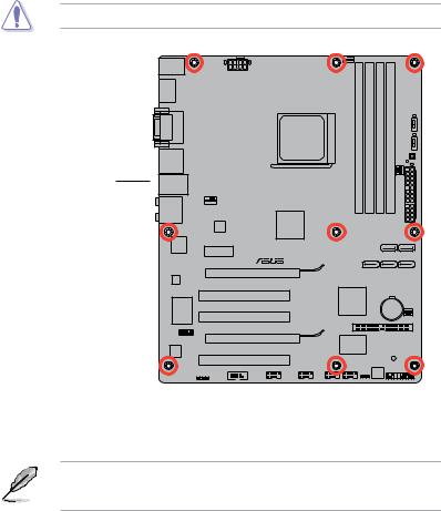
1.5.2Screw holes
Place nine screws into the holes indicated by circles to secure the motherboard to the chassis.
DO NOT overtighten the screws! Doing so can damage the motherboard.
Place this side towards the rear of the chassis.
M4A88T-V EVO/USB3
1.5.3Motherboard layout
ASUS M4A88T-V EVO Series motherboards include M4A88T-V EVO/USB3 and M4A88T-V EVO two models. The layout varies with models. The layout illustrations in this user guide are for M4A88T-V EVO/USB3 only.
ASUS M4A88T-V EVO Series |
1-7 |
KB_USB56
SPDIFO_
HDMI
 DVI_VGA
F_
ESATA_
USB34
LAN1_USB12
AUDIO
NEC
USB3.0
This USB 3.0 controller is provided for M4A88T-
V EVO/USB3 only. RTL
8111E
Super
I/O
AAFP
ALC 892
20
1 |
2 |
3 |
|
1 |
|
|
|
|
|
|
4 |
|
|
|
|
|
|
|
|
|
|
|
|
|
|||||||||||||||
|
|
|
|
|
|
|
|
|
|
24.4cm(9.6in) |
|
|
|
|
|
|
|
|
|
|
|
|
|
|
|
|
|
|
|
|
|
|
|
|
|||||
|
|
|
|
|
|
|
|
|
|
|
|
|
|
|
|
|
|
|
|
|
|
|
|
|
|
|
|
|
|
|
|
|
|
||||||
|
|
|
|
|
|
|
|
|
|
|
|
|
|
|
|
|
|
|
|
|
|
|
|
|
|
|
|
|
|
|
|
|
|
|
|
|
|
|
|
|
|
|
|
|
|
|
|
|
|
|
|
|
|
|
|
|
|
|
|
|
|
|
|
|
|
|
|
|
|
|
|
|
|
|
|
|
|
|
|
|
|
|
|
|
|
|
|
|
|
EATX12V |
|
|
CPU_FAN |
|
|
|
|
|
|
|
|
|
|
|
|
|
|
|
|
|
|
||||||||
|
|
|
|
|
|
|
|
|
|
|
|
|
|
|
|
|
|
|
|
|
|
|
|
|
|
|
|
|
|
|
|
|
|
|
|||||
|
|
|
|
|
|
|
|
|
|
|
|
|
|
|
|
|
|
|
|
|
|
|
|
|
|
|
|
|
|
|
|
|
|||||||
|
|
|
|
|
|
|
|
|
|
|
|
|
|
|
|
|
|
|
|
module) |
|
module) |
|
module) |
|
|
module) |
O2LED2 |
|
|
II |
||||||||
|
|
|
|
|
|
|
|
|
|
|
|
|
|
|
|
|
|
|
|
|
|
|
|
|
|
||||||||||||||
|
|
|
|
|
|
|
|
|
|
|
|
|
|
|
|
AM3 |
|
|
|
240-pin |
|
240-pin |
|
240-pin |
|
|
240-pin |
|
|
|
|
Turbo Key |
|||||||
|
|
|
|
|
|
|
|
|
|
|
|
|
|
|
|
SOCKET |
|
|
|
(64bit,A1DIMM |
|
(64bit,A2DIMM |
|
(64bit,B1DIMM |
|
|
(64bit,B2DIMM |
O2LED1 |
|
Core Unlocker |
|||||||||
|
|
|
|
|
|
|
|
|
|
|
|
|
|
|
|
|
|
|
|
|
|
|
|
|
|
|
|
|
|
|
|
|
|
|
|
|
|
|
|
|
|
|
|
|
|
|
|
|
|
|
|
|
|
|
|
|
|
|
|
|
|
|
|
|
|
|
|
|
|
|
|
|
|
|
MemOK! |
|
|||
|
|
|
|
|
|
|
|
|
|
|
|
|
|
|
|
|
|
|
|
|
|
|
|
|
|
|
|
|
|
|
|
|
|
|
|
|
|||
|
|
|
|
|
|
|
|
|
|
|
|
|
|
|
|
|
|
|
|
|
|
|
|
|
|
|
|
|
|
|
|
|
|
|
|
DRAM_LED |
|||
|
|
|
|
|
|
|
|
|
|
|
|
|
|
|
|
|
|
|
|
DDR3 |
|
DDR3 |
|
DDR3 |
|
|
DDR3 |
|
|
|
|
|
|
||||||
|
|
|
|
|
|
|
|
|
|
|
|
|
|
|
|
|
|
|
|
|
|
|
|
FAN |
|
|
|
|
|||||||||||
|
|
|
|
|
|
|
|
|
|
|
|
|
|
|
|
|
|
|
|
|
|
|
|
|
|
|
|
|
|
|
|
|
|
|
PWR_ |
|
|
|
|
|
|
|
|
|
|
|
|
|
|
|
AMD® |
|
|
|
|
|
|
|
|
|
|
|
|
|
|
|
|
|
|
EATXPWR |
|
|
|
|
|||||
|
|
|
|
|
|
|
|
|
|
|
|
|
|
|
|
|
|
|
|
|
|
|
|
|
|
|
|
|
|
|
|
|
|||||||
CHA_FAN1 |
|
|
|
|
|
|
|
|
|
|
|
|
|
|
|
|
|
|
|
|
|
|
|
|
|
||||||||||||||
|
|
|
|
|
|
|
|
|
|
|
|
|
|
|
|
|
|
|
|
|
|
|
|
|
|
|
|
|
|
|
|
|
|
|
|
|
|
|
|
|
|
|
|
|
|
|
|
|
|
|
|
|
|
|
|
|
|
|
|
|
|
|
|
|
|
|
|
|
|
|
|
|
|
|
|
|
|
|
|
|
|
|
|
|
|
|
|
|
|
|
|
|
|
|
|
|
|
|
|
|
|
|
|
|
|
|
|
|
|
|
|
|
|
|
|
|
|
|
|
|
|
|
|
ICS |
|
|
|
|
|
|
880G |
|
|
|
|
|
|
|
|
|
|
|
|
|
|
|
|
|
|
|
|
|
|
|
|
|
|
||
|
|
|
|
477C |
|
|
|
|
|
|
|
|
|
|
|
|
|
|
|
|
|
|
|
|
|
|
|
|
|
|
|
|
|
|
|
||||
|
|
|
|
|
|
|
|
|
|
|
|
|
|
|
|
|
|
|
|
|
|
|
|
|
|
|
|
|
|
SATA6 |
SATA5 |
|
|
||||||
|
|
|
|
|
|
|
|
|
|
|
|
|
|
|
|
|
|
|
|
|
|
|
|
|
|
|
|
|
|
|
|
||||||||
|
|
|
|
|
|
|
|
|
|
|
|
|
|
|
|
|
|
|
|
|
|
|
|
|
|
|
|
|
|
|
|
||||||||
|
|
|
|
|
|
|
|
|
|
|
|
|
|
|
|
|
|
|
|
|
|
|
|
|
|
|
|
|
|
|
|
|
|
|
|
|
|
|
|
|
|
PCIEX1_1 |
|
|
|
|
|
|
|
|
|
|
|
|
|
|
|
|
|
|
|
|
|
|
|
|
|
|
|
|
|
|
|
|
|
||||
|
|
|
|
|
|
|
|
|
|
|
|
|
|
|
|
|
|
|
|
|
|
|
|
|
|
|
|
|
|
|
|
|
|
|
|
|
|
|
|
|
|
|
|
|
|
|
|
|
|
|
|
|
|
|
|
|
|
|
|
|
|
|
|
|
|
|
|
|
|
|
|
|
|
|
|
|
|
|
|
|
|
|
|
|
|
|
|
|
|
|
|
|
|
|
|
|
|
|
|
|
|
|
|
|
|
|
|
|
|
|
|
|
|
|
|
|
|
|
|
|
|
|
|
|
|
|
|
|
|
|
|
|
|
|
|
|
|
|
|
|
|
|
|
SATA3 |
|
SATA2 |
SATA1 |
|
|
||||||||||
|
|
|
|
|
|
|
|
|
PCIEX16_1 |
|
|
|
|
|
|
|
|
|
|
|
|
|
|
||||||||||||||||
|
|
|
|
|
|
|
|
|
|
|
|
|
|
|
|
|
|
|
|
|
|
|
|
|
|
|
|
|
|
|
|
|
|
|
|
||||
|
|
|
|
|
|
|
|
|
|
|
|
|
|
|
|
|
|
|
|
|
|
|
|
|
|
|
|
|
|
|
|
|
|
|
|
|
|
|
|
|
|
|
|
M4A88T-V EVO/USB3 |
|
|
|
|
|
|
|
|
|
|
|
|
|
|
|
|
|
|
|
|
|
|
|
||||||||||||
|
|
|
|
|
|
|
|
PCI1 |
|
|
|
|
|
|
AMD® |
|
|
|
|
|
|
|
|
|
|
|
|
|
|
|
|
|
|||||||
|
|
|
|
|
|
|
|
|
|
|
|
|
|
|
|
|
|
SB710 |
|
|
|
|
|
|
|
Lithium Cell |
|
|
|
|
|||||||||
|
|
|
|
|
|
|
|
|
|
|
|
|
|
|
|
|
|
|
|
|
|
|
|
|
|
|
|
|
CMOS Power |
|
|
|
|
||||||
|
|
|
|
|
|
|
|
PCI2 |
|
|
|
|
|
|
|
PRI_IDE |
|
|
|
|
|
|
|
|
|
|
|
|
CHA_FAN2 |
||||||||||
|
|
|
|
|
|
|
|
|
|
|
|
|
|
|
|
|
|
|
|
|
|
|
|
|
|
|
|
|
|
|
|||||||||
|
|
|
|
|
|
|
|
|
|
|
|
|
|
|
|
|
|
|
|
|
|
|
|
|
|
|
|
|
|
|
|
|
|
||||||
|
|
|
|
|
|
|
|
|
|
|
|
|
|
|
|
|
|
|
|
|
|
|
|
|
|
|
|
|
|
|
|
|
|
|
|
|
|
|
|
|
|
|
|
|
|
|
|
|
|
|
|
|
|
|
|
|
|
|
|
|
|
|
|
|
|
|
|
|
|
|
|
|
|
|
|
|
|
|
|
|
|
|
|
|
|
|
|
|
PCIEX16_2 |
|
|
|
|
|
|
|
|
|
|
|
|
|
|
|
|
|
|
|
|
|
|
|
|
|
|
|
|||
|
|
|
|
|
|
|
|
|
|
|
|
|
|
|
|
|
|
VT6308P |
|
|
|
|
|
|
SB_PWR |
|
|
|
|
|
|||||||||
|
|
|
|
|
|
|
|
|
|
|
|
|
|
|
|
|
|
|
|
|
|
|
|
|
|
|
|
|
|||||||||||
|
|
|
|
|
|
|
|
|
|
|
|
|
|
|
|
|
|
|
|
|
|
|
|
|
|
|
|
|
|
|
|
|
|
||||||
|
|
|
|
|
|
|
|
PCI3 |
|
|
|
|
|
|
|
|
|
|
|
|
|
|
|
|
|
|
|
|
|
|
|
|
|
|
|
|
|||
|
|
|
|
|
|
|
|
|
|
|
|
|
|
|
|
|
|
|
|
|
|
|
|
|
|
|
|
|
|
|
|
|
|
|
|
|
|
|
|
SPDIF_OUTCOM1 |
|
|
16Mb |
PANEL |
USB78 |
USB910 |
BIOS |
|
|
|
USB1112 IE1394_1 CLRTC |
|
19 |
18 |
17 |
16 |
15 |
14 |
1
5
6
7
8
9
10
2
30.5cm(12.0in)
 11 9
11 9
1
12
13
1.5.4Layout contents
Connectors/Jumpers/Slots/LED |
Page |
Connectors/Jumpers/Slots/LED |
Page |
||
1. |
CPU, chassis, and power fan connectors |
1-24 |
11. |
SATA 3Gb/s connectors (7-pin SATA1~6) |
1-27 |
|
(4-pin CPU_FAN, 4-pin CHA_FAN1, 3-pin CHA_FAN2, |
|
|
|
|
|
and 3-pin PWR_FAN) |
|
|
|
|
2. |
ATX power connectors (24-pin EATXPWR, 8-pin EATX12V) |
1-25 |
12. |
IDE connector (40-1 pin PRI_IDE) |
1-26 |
3. |
AM3 CPU socket |
1-9 |
13. |
Standby power LED (SB_PWR) |
1-35 |
4. |
DDR3 DIMM slots |
1-12 |
14. |
System panel connector (20-8 pin PANEL) |
1-28 |
5. |
Turbo Key II LED (02LED2) |
1-36 |
15. |
Clear RTC RAM (3-pin CLRTC) |
1-20 |
6. |
Turbo Key II switch (TURBO_KEY_II) |
1-34 |
16. |
IEEE 1394a connector (10-1 pin IE1394_1) |
1-31 |
7. |
Core Unlocker LED (02LED1) |
1-36 |
17. |
USB connectors (10-1 pin USB78, USB910, |
1-29 |
|
|
|
|
USB1112) |
|
8. |
Core Unlocker switch (CORE_UNLOCKER) |
1-32 |
18. |
Serial port connector (10-1 pin COM1) |
1-29 |
9. |
MemOK! switch |
1-33 |
19. |
Digital audio connector (4-1 pin SPDIF_OUT) |
1-30 |
10. |
DRAM LED (DRAM_LED) |
1-35 |
20. |
Front panel audio connector (10-1 pin AAFP) |
1-30 |
1-8 |
Chapter 1: Product introduction |
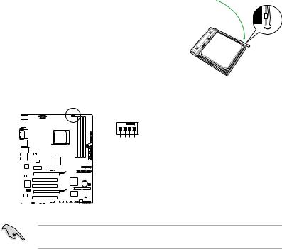
1.6Central Processing Unit (CPU)
This motherboard comes with an AM3 socket designed for Phenom™ II / Athlon™ II / Sempron™ 100 series processors.
The AM3 socket has a different pinout from the AM2+/AM2 socket. Ensure that you use a
CPU designed for theAM3 socket. The CPU fits in only one correct orientation. DO NOT force the CPU into the socket to prevent bending the pins and damaging the CPU!
1.6.1Installing the CPU
To install a CPU:
1.Locate the CPU socket on the motherboard.
M4A88T-V EVO/USB3
M4A88T-V EVO/USB3 CPU socket AM3
2. |
Press the lever sideways to unlock the |
Socket lever |
|
socket, then lift it up to a 90°-100° angle. |
|
Ensure that the socket lever is lifted up to a 90°-100° angle; otherwise, the CPU will not fit in completely.
3.Position the CPU above the socket such that the CPU corner with the gold triangle matches the socket corner with a small triangle.
4. Carefully insert the CPU into the socket until it fits in place.
The CPU fits only in one correct orientation.
DO NOT force the CPU into the socket to prevent bending the pins and damaging the CPU!
Small triangle
Gold triangle
ASUS M4A88T-V EVO Series |
1-9 |
5.When the CPU is in place, push down the socket lever to secure the CPU. The lever clicks on the side tab to indicate that it is locked.
6. Install a CPU heatsink and fan following the instructions that comes with the heatsink package. You can also refer to section 1.6.2 Installing heatsink and fan for instructions.
7.Connect the CPU fan cable to the CPU_FAN connector on the motherboard.
 CPU_FAN
GND
CPU FAN PWR
CPU FAN IN
CPU FAN PWM
M4A88T-V EVO/USB3
M4A88T-V EVO/USB3 CPU fan connector
DO NOT forget to connect the CPU fan connector! Hardware monitoring errors can occur if you fail to plug this connector.
1-10 |
Chapter 1: Product introduction |

1.6.2Installing the heatsink and fan
Ensure that you use onlyAMD-certified heatsink and fan assembly.
To install the CPU heatsink and fan:
1.Place the heatsink on top of the installed CPU, ensuring that the heatsink fits properly on the retention module base.
• The retention module base is already installed on the motherboard upon purchase.
• You do not have to remove the retention module base when installing the CPU or installing other motherboard components.
•If you purchased a separate CPU heatsink and fan assembly, ensure that a Thermal Interface Material is properly applied to the CPU heatsink or CPU before you install the heatsink and fan assembly.
CPU Fan
CPU Heatsink 

Retention bracket 
Retention Module Base
Retention bracket lock
Your boxed CPU heatsink and fan assembly should come with installation instructions for the CPU, heatsink, and the retention mechanism. If the instructions in this section do not match the CPU documentation, follow the latter.
2.Attach one end of the retention bracket to the retention module base.
1
2
3 |
4 |
|
5 |
ASUS M4A88T-V EVO Series |
1-11 |
3.Align the other end of the retention bracket to the retention module base. A clicking sound denotes that the retention bracket is in place.
Ensure that the fan and heatsink assembly perfectly fits the retention mechanism module base, otherwise you cannot snap the retention bracket in place.
4.Push down the retention bracket lock on the retention mechanism to secure the heatsink and fan to the module base.
5.When the fan and heatsink assembly is in place, connect the CPU fan cable to the connector on the motherboard labeled CPU_FAN.
DO NOT forget to connect the CPU fan connector! Hardware monitoring errors can occur if you fail to plug this connector.
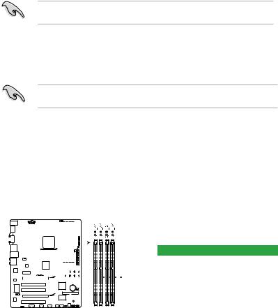
1.7System memory
1.7.1Overview
This motherboard comes with four Double Data Rate 3 (DDR3) Dual Inline Memory Modules (DIMM) sockets. A DDR3 module has the same physical dimensions as a DDR2 DIMM but is notched differently to prevent installation on a DDR2 DIMM socket. DDR3 modules are developed for better performance with less power consumption. The figure illustrates the location of the DDR3 DIMM sockets:
|
|
|
|
|
|
|
|
|
|
|
|
|
|
|
|
|
|
|
|
|
|
|
|
|
|
|
|
|
|
|
|
|
|
|
|
|
|
|
|
|
|
|
|
|
|
|
|
|
|
|
|
|
|
|
|
|
|
|
|
|
|
|
|
|
|
|
|
|
|
|
|
|
|
|
|
|
|
|
|
|
|
|
|
|
|
|
|
|
|
|
|
|
|
|
|
|
|
|
|
|
|
|
|
|
|
|
|
|
|
|
|
|
|
|
|
|
|
|
|
|
|
|
|
|
|
|
|
|
|
|
|
|
|
|
|
|
|
Channel |
Sockets |
|
|
|
|
|
|
|
|
|
|
|
|
|
|
|
|
||||
|
|
|
|
|
|
|
|
|
|
|
|
|
|
|
|
|
|
||
|
|
|
|
|
|
|
|
|
|
|
|
|
|
|
|
||||
|
|
|
|
|
|
|
|
|
|
|
|
|
|
|
|
|
|
Channel A |
DIMM_A1 and DIMM_A2 |
|
|
|
|
|
|
|
|
|
|
|
|
|
|
|
|
||||
|
|
|
|
|
|
|
|
|
|
|
|
|
|
|
|
|
|
Channel B |
DIMM_B1 and DIMM_B2 |
|
|
|
|
|
|
|
|
|
|
|
|
|
|
|
|
||||
|
|
|
|
|
|
|
|
|
|
|
|
|
|
|
|
||||
|
|
|
|
|
|
|
|
|
|
|
|
|
|
|
|
||||
|
|
|
|
|
|
|
|
|
|
|
|
|
|
|
|
||||
|
|
|
|
|
|
|
|
|
|
|
|
|
|
|
|
|
|
|
|
|
|
|
|
|
|
|
|
|
|
|
|
|
|
|
|
|
|
|
|
|
|
|
|
|
|
|
|
|
|
|
|
|
|
|
|
|
|
|
|
|
|
|
|
|
|
|
|
|
|
|
|
|
|
|
|
|
|
|
|
M4A88T-V EVO/USB3
M4A88T-V EVO/USB3 240-pin DDR3 DIMM sockets
1-12 |
Chapter 1: Product introduction |

1.7.2Memory configurations
You may install 512MB, 1GB, 2GB, and 4GB unbuffered ECC and non-ECC DDR3 DIMMs into the DIMM sockets.
• You may install varying memory sizes in ChannelAand Channel B. The system maps the total size of the lower-sized channel for the dual-channel configuration.Any excess memory from the higher-sized channel is then mapped for single-channel operation.
•We recommend that you install the memory modules from the blue slots for better overclocking capability.
•Always install DIMMs with the same CAS latency. For optimum compatibility, we recommend that you obtain memory modules from the same vendor.
•Due to CPU spec., AMD® 100 and 200 series CPUs support up to DDR3 1066MHz. With ASUS design, this motherboard can support up to DDR3 1333MHz.
•When overclocking, someAMD CPU models may not support DDR3 1600 MHz or higher frequency DIMMs.
•Due to the memory address limitation on 32-bit Windows® OS, when you install 4GB or more memory on the motherboard, the actual usable memory for the OS can be about 3GB or less. For effective use of memory, we recommend that you do any of the following:
-Install a maximum of 3GB system memory if you are using a 32-bit Windows® OS.
-Use a 64-bit Windows® OS if you want to install 4GB or more memory on the motherboard.
•This motherboard does not support DIMMs made up of 256 megabits (Mb) chips or less.
• The default memory operation frequency is dependent on its Serial Presence Detect (SPD), which is the standard way of accessing information from a memory module. Under the default state, some memory modules for overclocking may operate at a lower frequency than the vendor-marked value. To operate at the vendor-marked or at a higher frequency, refer to section 2.4 Ai Tweaker menu for manual memory frequency adjustment.
•For system stability, use a more efficient memory cooling system to support a full memory load (4 DIMMs) or overclocking condition.
M4A88T-V EVO Series Motherboard Qualified Vendors Lists (QVL)
DDR3-2000(O.C.)MHz capability
Vendor |
Part No. |
Size |
SS/ |
Chip |
Chip |
Timing |
Voltage |
DIMM socket support |
|
|
(Optional) |
|
|
||||||||
|
|
|
DS |
Brand |
NO. |
|
|
A* |
B* |
C* |
|
|
|
|
|
|
|
|
|||
KINGSTON |
KHX2000C8D3T1K3/3GX(XMP) |
3072MB(kit of 3) |
SS |
- |
- |
- |
1.65V |
• |
|
|
KINGSTON |
KHX2000C9D3T1K3/3GX(XMP) |
3072MB(kit of 3) |
SS |
- |
- |
- |
1.65V |
• |
|
|
KINGSTON |
KHX2000C8D3T1K3/6GX(XMP) |
6144MB(Kit of 3) |
DS |
- |
- |
- |
1.65V |
• |
|
|
Transcend |
TX2000KLU-4GK(XMP) |
4096MB(Kit of 2) |
DS |
- |
- |
9-9-9-24 |
1.65V |
• |
|
|
1-13

DDR3-1866(O.C.)MHz capability
Vendor |
Part No. |
Size |
SS/DS |
Chip |
Chip NO. |
Timing |
Voltage |
DIMM socket |
|
|
support (Optional) |
||||||||||
|
|
|
|
Brand |
|
|
|
A* |
B* |
C* |
|
|
|
|
|
|
|
|
|||
CORSAIR |
CMG6GX3M3A1866C7(XMP) |
6144MB(Kit of 3) |
DS |
- |
- |
7-8-7-20 |
1.65V |
• |
• |
|
KINGSTON |
KHX1866C9D3T1K3/6GX(XMP) |
6144MB(Kit of 3) |
DS |
- |
- |
- |
1.65V |
• |
• |
|
OCZ |
OCZ3P1866LV4GK |
4096MB(Kit of 2) |
DS |
- |
- |
9-9-9-27 |
1.65V |
• |
• |
|
OCZ |
OCZ3P1866C9LV6GK |
6144MB(Kit of 3) |
DS |
- |
- |
9-9-9-28 |
1.65V |
• |
• |
|
DDR3-1800(O.C.)MHz capability
Vendor |
Part No. |
Size |
SS/DS |
Chip Brand |
Chip NO. |
Timing |
Voltage |
DIMM socket support |
|
|
(Optional) |
B* |
C* |
||||||||
|
|
|
|
|
|
|
|
A* |
||
OCZ |
OCZ3P18004GK |
4096MB(Kit of 2) |
DS |
- |
- |
8-8-8-27 |
1.9V |
• |
• |
|
OCZ |
QCZ3P18004GK |
4096MB(Kit of 2) |
DS |
- |
- |
8-8-8-27 |
1.9V |
• |
• |
|
DDR3-1600(O.C.)MHz capability
Vendor |
Part No. |
Size |
SS/ |
Chip |
Chip NO. |
Timing |
Voltage |
DIMM socket |
|
|
support (Optional) |
||||||||||
|
|
|
DS |
Brand |
|
|
|
A* |
B* |
C* |
A-Data |
AD31600E001GM(O)U3K |
3072MB(Kit of 3) |
SS |
- |
- |
8-8-8-24 |
1.65V-1.85V |
• |
• |
• |
A-Data |
AD31600X002GMU(XMP) |
4096MB(Kit of 2) |
DS |
- |
- |
7-7-7-20 |
1.75-1.85V |
• |
• |
• |
CORSAIR |
TR3X3G1600C8D(XMP) |
3072MB(Kit of 3) |
SS |
- |
- |
8-8-8-24 |
1.65V |
• |
• |
• |
CORSAIR |
CMX4GX3M2A1600C9(XMP) |
4096MB(Kit of 2) |
DS |
- |
- |
9-9-9-24 |
1.65V |
• |
• |
|
CORSAIR |
CMX4GX3M2A1600C9(XMP) |
4096MB(Kit of 2) |
DS |
- |
- |
9-9-9-24 |
1.65V |
• |
• |
• |
CORSAIR |
TR3X6G1600C8 G(XMP) |
6144MB(Kit of 3) |
DS |
- |
- |
- |
- |
• |
• |
• |
CORSAIR |
TR3X6G1600C8D G(XMP) |
6144MB(Kit of 3) |
DS |
- |
- |
8-8-8-24 |
1.65V |
• |
• |
|
CORSAIR |
TR3X6G1600C9 G(XMP) |
6144MB(Kit of 3) |
DS |
- |
- |
9-9-9-24 |
1.65V |
• |
• |
• |
CORSAIR |
TR3X6G1600C8D G(XMP) |
6144MB(Kit of 3) |
DS |
- |
- |
8-8-8-24 |
1.65V |
• |
• |
• |
CORSAIR |
CMX8GX3M4A1600C9(XMP) |
8192MB(Kit of 4) |
DS |
- |
- |
9-9-9-24 |
1.65V |
• |
• |
• |
Crucial |
BL12864BA1608.8SFB(XMP) |
3072MB(Kit of 3) |
SS |
- |
- |
8-8-8-24 |
1.8V |
• |
• |
• |
Crucial |
BL12864BE2009.8SFB3(EPP) |
3072MB(Kit of 3) |
SS |
- |
- |
9-9-9-28 |
2.0V |
• |
• |
• |
Crucial |
BL25664BN1608.16FF(XMP) |
6144MB(Kit of 3) |
DS |
- |
- |
- |
- |
• |
• |
|
Crucial |
BL25664TB1608.K16SF(XMP) |
6144MB(Kit of 3) |
DS |
- |
- |
8-8-8-24 |
- |
• |
• |
• |
Crucial |
BL25664TG1608.K16SF(XMP) |
6144MB(Kit of 3) |
DS |
- |
- |
8-8-8-24 |
- |
• |
• |
• |
Crucial |
BL25664TR1608.K16SF(XMP) |
6144MB(Kit of 3) |
DS |
- |
- |
8-8-8-24 |
- |
• |
• |
• |
G.SKILL |
F3-12800CL9D-2GBNQ(XMP) |
2048MB(Kit of 2) |
SS |
- |
- |
9-9-9-24 |
1.5V~1.6V |
• |
• |
• |
G.SKILL |
F3-12800CL7D-4GBECO(XMP) |
4096MB(Kit of 2) |
DS |
- |
- |
7-8-7-24 |
1.35V(low |
• |
• |
• |
voltage) |
||||||||||
G.SKILL |
F3-12800CL8D-4GBRM(XMP) |
4096MB(Kit of 2) |
DS |
- |
- |
8-8-8-24 |
1.60V |
• |
• |
• |
G.SKILL |
F3-12800CL9D-4GBECO(XMP) |
4096MB(Kit of 2) |
DS |
- |
- |
9-9-9-24 |
1.35V(low |
• |
• |
• |
voltage) |
||||||||||
G.SkiLL |
F3-12800CL8T-6GBPI(XMP) |
6144MB(Kit of 3) |
DS |
- |
- |
8-8-8-21 |
1.6-1.65V |
• |
|
|
G.SKILL |
F3-12800CL9T-6GBNQ(XMP) |
6144MB(Kit of 3) |
DS |
- |
- |
9-9-9-24 |
1.5V~1.6V |
• |
• |
• |
Kingmax |
FLGD45F-B8KG9(XMP) |
1024MB |
SS |
Kingmax |
KFB8FNGXF-ANX-12A |
- |
- |
• |
• |
• |
Kingmax |
FLGD45F-B8MF7 MAEH(XMP) |
1024MB |
SS |
- |
- |
7 |
- |
• |
• |
• |
Kingmax |
FLGE85F-B8KG9(XMP) |
2048MB |
DS |
Kingmax |
KFB8FNGXF-ANX-12A |
- |
- |
• |
• |
• |
Kingmax |
FLGE85F-B8MF7 MEEH(XMP) |
2048MB |
DS |
- |
- |
7 |
- |
• |
• |
|
KINGSTON |
KHX1600C8D3K2/4GX(XMP) |
4096MB(Kit of 2) |
DS |
- |
- |
- |
1.65V |
• |
• |
• |
KINGSTON |
KHX1600C8D3T1K2/4GX(XMP) |
4096MB(Kit of 2) |
DS |
- |
- |
- |
1.65V |
• |
• |
• |
KINGSTON |
KHX1600C9D3K2/4G |
4096MB(kit of 2) |
DS |
- |
- |
- |
1.7-1.9V |
• |
• |
• |
KINGSTON |
KHX1600C9D3K3/6GX(XMP) |
6144MB(Kit of 3) |
DS |
- |
- |
- |
1.65V |
• |
• |
• |
OCZ |
OCZ3G1600LV3GK |
3072MB(Kit of 3) |
SS |
- |
- |
8-8-8-24 |
1.65V |
• |
• |
|
OCZ |
OCZ3BE1600C8LV4GK |
4096MB(Kit of 2) |
DS |
- |
- |
8-8-8-24 |
1.65V |
• |
• |
• |
OCZ |
OCZ3BE1600LV4GK |
4096MB(Kit of 2) |
DS |
- |
- |
7-7-7-24 |
1.65V |
• |
• |
|
OCZ |
OCZ3OB1600LV4GK |
4096MB(Kit of 2) |
DS |
- |
- |
- |
1.65V |
• |
• |
• |
OCZ |
OCZ3P1600LV4GK |
4096MB(Kit of 2) |
DS |
- |
- |
7-7-7-24 |
1.65V |
• |
• |
• |
OCZ |
OCZ3G1600LV6GK |
6144MB(Kit of 3) |
DS |
- |
- |
8-8-8-24 |
1.65V |
• |
• |
• |
Super Talent |
WA160UX6G9 |
6144MB(Kit of 3) |
DS |
- |
- |
9 |
- |
• |
• |
• |
Elixir |
M2Y2G64CB8HA9N-DG(XMP) |
2048MB |
DS |
- |
- |
- |
- |
• |
• |
• |
Kingtiger |
KTG2G1600PG3 |
2048MB |
DS |
- |
- |
- |
- |
• |
• |
• |
Mushkin |
996657(XMP) |
4096MB(Kit of 2) |
DS |
- |
- |
7-7-7-20 |
1.95V |
• |
• |
• |
Mushkin |
998659(XMP) |
6144MB(Kit of 3) |
DS |
- |
- |
9-9-9-24 |
1.5~1.6V |
• |
• |
|
Mushkin |
998659(XMP) |
6144MB(Kit of 3) |
DS |
- |
- |
9-9-9-24 |
- |
• |
• |
• |
PATRIOT |
PGS34G1600LLKA |
4096MB(Kit of 2) |
DS |
- |
- |
7-7-7-20 |
1.7V |
• |
• |
• |
1-14 |
Chapter 1: Product introduction |
 Loading...