


M2R32-MVP
Motherboard

E2770
Second Edition V2
August 2006
Copyright © 2006 ASUSTeK COMPUTER INC. All Rights Reserved.
No part of this manual, including the products and software described in it, may be reproduced, transmitted, transcribed, stored in a retrieval system, or translated into any language in any form or by any means, except documentation kept by the purchaser for backup purposes, without the express written permission of ASUSTeK COMPUTER INC. (“ASUS”).
Product warranty or service will not be extended if: (1) the product is repaired, modified or altered, unless such repair, modification of alteration is authorized in writing by ASUS; or (2) the serial number of the product is defaced or missing.
ASUS PROVIDES THIS MANUAL “AS IS” WITHOUT WARRANTY OF ANY KIND, EITHER EXPRESS OR IMPLIED, INCLUDING BUT NOT LIMITED TO THE IMPLIED WARRANTIES OR CONDITIONS OF MERCHANTABILITY OR FITNESS FOR A PARTICULAR PURPOSE. IN NO EVENT SHALL ASUS, ITS DIRECTORS, OFFICERS, EMPLOYEES OR AGENTS BE LIABLE FOR ANY INDIRECT, SPECIAL, INCIDENTAL, OR CONSEQUENTIAL DAMAGES (INCLUDING DAMAGES FOR LOSS OF PROFITS, LOSS OF BUSINESS, LOSS OF USE OR DATA, INTERRUPTION OF BUSINESS AND THE LIKE), EVEN IF ASUS HAS BEEN ADVISED OF THE POSSIBILITY OF SUCH DAMAGES ARISING FROM ANY DEFECT OR ERROR IN THIS MANUAL OR PRODUCT.
SPECIFICATIONS AND INFORMATION CONTAINED IN THIS MANUAL ARE FURNISHED FOR INFORMATIONAL USE ONLY, AND ARE SUBJECT TO CHANGE AT ANY TIME WITHOUT NOTICE, AND SHOULD NOT BE CONSTRUED AS A COMMITMENT BY ASUS. ASUS ASSUMES NO RESPONSIBILITY OR LIABILITY FOR ANY ERRORS OR INACCURACIES THAT MAY APPEAR IN THIS MANUAL, INCLUDING THE PRODUCTS AND SOFTWARE DESCRIBED IN IT.
Products and corporate names appearing in this manual may or may not be registered trademarks or copyrights of their respective companies, and are used only for identification or explanation and to the owners’ benefit, without intent to infringe.
i i

Contents
Notices ............................................................................................... |
vii |
Safety information ............................................................................ |
viii |
About this guide ................................................................................. |
ix |
M2R32-MVP specifications summary .................................................. |
xi |
Chapter 1: |
Product introduction |
|
|
1.1 |
Welcome! .............................................................................. |
1-1 |
|
1.2 |
Package contents ................................................................. |
1-1 |
|
1.3 |
Special features .................................................................... |
1-2 |
|
|
1.3.1 |
Product highlights................................................... |
1-2 |
|
1.3.2 |
Innovative ASUS features ....................................... |
1-4 |
Chapter 2: |
Hardware information |
|
|
2.1 |
Before you proceed .............................................................. |
2-1 |
|
2.2 |
Motherboard overview .......................................................... |
2-2 |
|
|
2.2.1 |
Placement direction ................................................ |
2-2 |
|
2.2.2 |
Screw holes ............................................................ |
2-2 |
|
2.2.3 |
Motherboard layout ................................................ |
2-3 |
|
2.2.4 |
Layout Contents ..................................................... |
2-4 |
2.3 |
Central Processing Unit (CPU) .............................................. |
2-6 |
|
|
2.3.1 |
Installing the CPU.................................................... |
2-6 |
|
2.3.2 Installing the heatsink and fan ................................ |
2-8 |
|
2.4 |
System memory ................................................................. |
2-11 |
|
|
2.4.1 |
Overview ............................................................... |
2-11 |
|
2.4.2 |
Memory Configurations......................................... |
2-12 |
|
2.4.3 Installing a DDR2 DIMM ......................................... |
2-16 |
|
|
2.4.4 Removing a DDR2 DIMM ........................................ |
2-16 |
|
2.5 |
Expansion slots ................................................................... |
2-17 |
|
|
2.5.1 Installing an expansion card .................................. |
2-17 |
|
|
2.5.2 Configuring an expansion card.............................. |
2-17 |
|
|
2.5.3 |
Interrupt assignments .......................................... |
2-18 |
|
2.5.4 |
Two PCI slots ........................................................ |
2-19 |
|
2.5.5 Two PCI Express x1 slots ...................................... |
2-19 |
|
|
2.5.6 Two PCI Express x16 slots ................................... |
2-19 |
|
i i i

Contents
2.6 |
Jumper |
............................................................................... |
2-21 |
2.7 |
Connectors ......................................................................... |
2-24 |
|
|
2.7.1 |
Rear panel connectors .......................................... |
2-24 |
|
2.7.2 |
Internal connectors............................................... |
2-26 |
Chapter 3: Powering up |
|
||
3.1 |
Starting up for the first time................................................ |
3-1 |
|
3.2 |
Powering off the computer .................................................. |
3-2 |
|
|
3.2.1 |
Using the OS shut down function ........................... |
3-2 |
|
3.2.2 |
Using the dual function power switch .................... |
3-2 |
Chapter 4: |
BIOS Setup |
|
|
4.1 Managing and updating your BIOS ........................................ |
4-1 |
||
|
4.1.1 |
ASUS Update utility ................................................ |
4-1 |
|
4.1.2 Creating a bootable floppy disk .............................. |
4-4 |
|
|
4.1.3 ASUS EZ Flash utility .............................................. |
4-5 |
|
|
4.1.4 |
AFUDOS utility ........................................................ |
4-6 |
|
4.1.5 ASUS CrashFree BIOS 2 utility ................................ |
4-9 |
|
4.2 |
BIOS setup program ........................................................... |
4-11 |
|
|
4.2.1 |
BIOS menu screen................................................. |
4-12 |
|
4.2.2 |
Menu bar ............................................................... |
4-12 |
|
4.2.3 |
Navigation keys .................................................... |
4-12 |
|
4.2.4 |
Menu items ........................................................... |
4-13 |
|
4.2.5 |
Sub-menu items ................................................... |
4-13 |
|
4.2.6 |
Configuration fields .............................................. |
4-13 |
|
4.2.7 |
Pop-up window ..................................................... |
4-13 |
|
4.2.8 |
Scroll bar .............................................................. |
4-13 |
|
4.2.9 |
General help .......................................................... |
4-13 |
4.3 |
Main menu .......................................................................... |
4-14 |
|
|
4.3.1 |
System Time......................................................... |
4-14 |
|
4.3.2 |
System Date ......................................................... |
4-14 |
|
4.3.3 |
Legacy Diskette A ................................................ |
4-14 |
|
4.3.4 |
Language .............................................................. |
4-14 |
4.3.5Primary IDE Master/Slave
|
SATA1-4 ............................................................... |
4-15 |
4.3.6 |
Storage Configuration .......................................... |
4-16 |
4.3.7 |
System Information .............................................. |
4-17 |
i v

4.4 |
Advanced menu .................................................................. |
4-18 |
|
|
4.4.1 |
JumperFree Configuration .................................... |
4-18 |
|
4.4.2 |
CPU Configuration................................................. |
4-22 |
|
4.4.3 |
Chipset ................................................................. |
4-25 |
|
4.4.4 |
Onboard Devices Configuration ............................ |
4-27 |
|
4.4.5 |
PCI PnP ................................................................. |
4-29 |
|
4.4.6 |
USB Configuration................................................. |
4-30 |
4.5 |
Power menu ........................................................................ |
4-32 |
|
|
4.5.1 |
Suspend Mode ...................................................... |
4-32 |
|
4.5.2 Repost Video on S3 Resume ................................ |
4-32 |
|
|
4.5.3 |
ACPI Version Features .......................................... |
4-32 |
|
4.5.4 |
ACPI APIC Support ................................................ |
4-32 |
|
4.5.5 |
APM Configuration ................................................ |
4-33 |
|
4.5.6 |
Hardware Monitor ................................................. |
4-35 |
4.6 |
Boot menu .......................................................................... |
4-37 |
|
|
4.6.1 |
Boot Device Priority .............................................. |
4-37 |
|
4.6.2 |
Boot Settings Configuration ................................. |
4-38 |
|
4.6.3 |
Security ................................................................ |
4-38 |
4.7 |
Tools menu ......................................................................... |
4-42 |
|
|
4.7.1 ASUS EZ Flash 2 ................................................... |
4-42 |
|
|
4.7.2 |
ASUS O.C. Profile .................................................. |
4-43 |
4.8 |
Exit menu ........................................................................... |
4-45 |
|
Chapter 5: |
Software support |
|
5.1 Installing an operating system ............................................. |
5-1 |
|
5.2 Support CD information ........................................................ |
5-1 |
|
5.2.1 Running the support CD ......................................... |
5-1 |
|
5.2.2 |
Drivers menu .......................................................... |
5-2 |
5.2.3 |
Utilities menu .......................................................... |
5-3 |
5.2.4 |
Make Disk menu ...................................................... |
5-5 |
5.2.5 |
Manuals menu ......................................................... |
5-6 |
5.2.6 |
ASUS Contact information ...................................... |
5-7 |
5.2.7 |
Other information ................................................... |
5-7 |
v

5.4 |
Software information ........................................................... |
5-9 |
|
|
5.3.1 |
ASUS MyLogo2™ .................................................... |
5-9 |
|
5.3.2 |
AI Net 2 ................................................................ |
5-11 |
|
5.3.3 ASUS PC Probe II ................................................... |
5-12 |
|
|
5.3.4 Cool ‘n’ Quiet™ Technology .................................. |
5-18 |
|
|
5.3.5 SoundMAX® High Definition Audio utility .............. |
5-20 |
|
5.4 |
RAID configurations ............................................................ |
5-25 |
|
|
5.4.1 |
Installing hard disks .............................................. |
5-26 |
|
5.4.2 |
ATI® RAID configurations ...................................... |
5-26 |
5.5 |
Creating a RAID driver disk ................................................. |
5-32 |
|
Chapter 6: ATI CrossFire™ technology |
support |
|
6.1 |
Overview............................................................................... |
6-1 |
|
Requirements ....................................................................... |
6-1 |
|
Before you begin .................................................................. |
6-1 |
6.2 |
Hardware installation ............................................................ |
6-2 |
|
Installing CrossFire™ graphics cards ..................................... |
6-2 |
6.3 |
Software information ........................................................... |
6-5 |
|
6.3.1 Installing the device drivers .................................... |
6-5 |
|
6.3.2 Using the Catalyst™ Control Center ....................... |
6-7 |
v i

Notices
Federal Communications Commission Statement
This device complies with Part 15 of the FCC Rules. Operation is subject to the following two conditions:
•This device may not cause harmful interference, and
•This device must accept any interference received including interference that may cause undesired operation.
This equipment has been tested and found to comply with the limits for a Class B digital device, pursuant to Part 15 of the FCC Rules. These limits are designed to provide reasonable protection against harmful interference in a residential installation. This equipment generates, uses and can radiate radio frequency energy and, if not installed and used in accordance with manufacturer’s instructions, may cause harmful interference to radio communications. However, there is no guarantee that interference will not occur in a particular installation. If this equipment does cause harmful interference to radio or television reception, which can be determined by turning the equipment off and on, the user is encouraged to try to correct the interference by one or more of the following measures:
•Reorient or relocate the receiving antenna.
•Increase the separation between the equipment and receiver.
•Connect the equipment to an outlet on a circuit different from that to which the receiver is connected.
•Consult the dealer or an experienced radio/TV technician for help.
The use of shielded cables for connection of the monitor to the graphics card is required to assure compliance with FCC regulations. Changes or modifications to this unit not expressly approved by the party responsible for compliance could void the user’s authority to operate this equipment.
Canadian Department of Communications Statement
This digital apparatus does not exceed the Class B limits for radio noise emissions from digital apparatus set out in the Radio Interference Regulations of the Canadian Department of Communications.
This class B digital apparatus complies with Canadian ICES-003.
v i i

Safety information
Electrical safety
•To prevent electrical shock hazard, disconnect the power cable from the electrical outlet before relocating the system.
•When adding or removing devices to or from the system, ensure that the power cables for the devices are unplugged before the signal cables are connected. If possible, disconnect all power cables from the existing system before you add a device.
•Before connecting or removing signal cables from the motherboard, ensure that all power cables are unplugged.
•Seek professional assistance before using an adapter or extension cord. These devices could interrupt the grounding circuit.
•Make sure that your power supply is set to the correct voltage in your area. If you are not sure about the voltage of the electrical outlet you are using, contact your local power company.
•If the power supply is broken, do not try to fix it by yourself. Contact a qualified service technician or your retailer.
Operation safety
•Before installing the motherboard and adding devices on it, carefully read all the manuals that came with the package.
•Before using the product, make sure all cables are correctly connected and the power cables are not damaged. If you detect any damage, contact your dealer immediately.
•To avoid short circuits, keep paper clips, screws, and staples away from connectors, slots, sockets and circuitry.
•Avoid dust, humidity, and temperature extremes. Do not place the product in any area where it may become wet.
•Place the product on a stable surface.
•If you encounter technical problems with the product, contact a qualified service technician or your retailer.
The symbol of the crossed out wheeled bin indicates that the product (electrical and electronic equipment) should not be placed in municipal waste. Please check local regulations for disposal of electronic products.
viii

About this guide
This user guide contains the information you need when installing and configuring the motherboard.
How this guide is organized
This guide contains the following parts:
•Chapter 1: Product introduction
This chapter describes the features of the motherboard and the new technology it supports.
•Chapter 2: Hardware information
This chapter lists the hardware setup procedures that you have to perform when installing system components. It includes description of the switches, jumpers, and connectors on the motherboard.
•Chapter 3: Powering up
This chapter describes the power up sequence, the vocal POST messages, and ways of shutting down the system.
•Chapter 4: BIOS setup
This chapter tells how to change system settings through the BIOS Setup menus. Detailed descriptions of the BIOS parameters are also provided.
•Chapter 5: Software support
This chapter describes the contents of the support CD that comes with the motherboard package.
•Chapter 6: ATI CrossFire™ technology support
This chapter tells how to install ATI CrossFire™ graphics cards.
Where to find more information
Refer to the following sources for additional information and for product and software updates.
1 . ASUS websites
The ASUS website provides updated information on ASUS hardware and software products. Refer to the ASUS contact information.
2 . Optional documentation
Your product package may include optional documentation, such as warranty flyers, that may have been added by your dealer. These documents are not part of the standard package.
i x

Conventions used in this guide
To make sure that you perform certain tasks properly, take note of the following symbols used throughout this manual.
DANGER/WARNING: Information to prevent injury to yourself when trying to complete a task.
CAUTION: Information to prevent damage to the components when trying to complete a task.
IMPORTANT: Instructions that you MUST follow to complete a task.
NOTE: Tips and additional information to help you complete a task.
Typography
Bol d text |
Indicates a menu or an item to select. |
Italics |
Used to emphasize a word or a phrase. |
<Key> |
Keys enclosed in the less-than and greater-than sign means |
|
that you must press the enclosed key. |
|
Example: <Enter> means that you must press the Enter or |
|
Return key. |
<Key1+Key2+Key3> |
If you must press two or more keys simultaneously, the |
|
key names are linked with a plus sign (+). |
|
Example: <Ctrl+Alt+D> |
Command |
Means that you must type the command exactly as shown, |
|
then supply the required item or value enclosed in |
|
brackets. |
|
Example: At the DOS prompt, type the command line: |
|
afudos /i[filename] |
|
afudos /iM2R32-MVP.ROM |
x
M2R32-MVP specifications summary
C P U
Chipset
System bus
Memory
Socket AM2 for AMD Athlon™ 64 X2/Athlon™ 64 FX/ Athlon™ 64/Sempron™ processor
AMD64 architecture enables simultaneous 32and 64-bit computing
Supports AMD Cool ‘n’ Quiet™ Technology Supports AMD HyperTransport™ Technology Supports AMD Live!™ Ready
ATI™ CrossFire™ Xpress 3200/ATI™ SB600
2000/1600 MT/s
Dual-channel memory architecture
4 x 240-pin DIMM sockets support up to 8 GB unbufferred ECC/non-ECC 800/667/533 MHz DDR2 memory modules
Expansion slots 2 x PCI Express™ x16 slots with CrossFire support at full x16, x16 mode
2 x PCI Express™ x1 slots
2 x PCI slots
CrossFire™
Storage
High Definition
Audio
L A N
IEEE 1394a
Supports ATI CrossFire™ graphics cards (both at x16 mode)
ATI SB600 Southbridge supports:
-1 x IDE connector for two Ultra DMA 133/100/66/33 hard disks
-4 x Serial ATA I/II 3.0 Gb/s hard disks with RAID 0, RAID 1, and RAID 0+1
JMicron® 360 SATA controller supports:
-1 x External Serial ATA 3.0Gb/s hard disk (SATA On- the-Go)
SoundMAX® ADI 1988A 8-channel High Definition Audio CODEC
Supports Multi-streaming and Universal Audio Jack Coaxial S/PDIF Out port on the rear panel
Marvell® 88E8001 Gigabit LAN controller, featuring AI NET2
VIA VT6308P controller supports:
-1 x IEEE 1394a connector at mid-board
-1 x IEEE 1394a connector at rear-board
U S B |
Supports up to 10 USB 2.0/1.1 ports |
BIOS features |
8 Mb Flash ROM, AMI BIOS, PnP, DMI2.0, SM BIOS 2.3, |
|
WfM2.0 |
|
|
|
(continued on the next page) |
x i

M2R32-MVP specifications summary
ASUS special |
Stack Cool 2 |
features |
ASUS SATA On-the-Go (External Serial ATA port on the |
|
rear panel) |
|
Noise Filter |
|
ASUS EZ DIY: |
|
- ASUS CrashFree BIOS 3 |
|
- ASUS EZ Flash 2 |
|
- ASUS Q-Connector |
|
ASUS MyLogo2 |
|
ASUS Q-Fan2 Technology |
|
|
Overclocking
Rear panel
Intelligent overclocking tools:
-AI NOS™ (Non-delay Overclocking System)
-AI Overclocking (intelligent CPU frequency tuner)
-AI Clock Skew
ASUS O.C. Profile: overclocking configuration-sharing tool
Precision Tweaker supports:
-DIMM voltage: 12-step DRAM voltage control
-Core voltage: Adjustable CPU voltage at 0.025 V
increment
Stepless Frequency Selection(SFS) allows:
-FSB tuning from 200 MHz to 400 MHz at 1 MHz increment
-PCI Express frequency tuning from 100 MHz to 150 MHz at 1 MHz increment
Overclocking protection:
- ASUS C.P.R. (CPU Parameter Recall)
1 x PS/2 mouse port
1 x PS/2 keyboard port
1 x LAN (RJ-45) port
4 x USB 2.0/1.1 ports
1 x IEEE1394a port
1 x Coaxial S/PDIF Out port
1 x External Serial ATA port
1 x Serial (COM) port
8-Channel audio ports
Manageabiity WfM 2.0, DMI 2.0, WOL by PME, WOR by PME, Chassis Intrusion, PXE, and RPL
(continued on the next page)
x i i

M2R32-MVP specifications summary
Internal |
3 x USB 2.0 connectors for six additional USB 2.0 ports |
|
connectors |
1 x Floppy disk drive connector |
|
|
1 x IDE connector |
|
|
4 x SATA connectors |
|
|
1 x IEEE1394a connector |
|
|
1 x CD audio in connector |
|
|
1 x S/PDIF Out connector |
|
|
1x CPU/2 x Chassis/1 x Power fan connectors |
|
|
1 x 24-pin EATX power connector |
|
|
1 x 4-pin ATX 12 V power connector |
|
|
Chassis intrusion connector |
|
|
Front panel High Definition Audio connector |
|
|
System panel connector |
|
|
|
|
Support CD |
Drivers |
|
contents |
ASUS PC Probe II |
|
|
ASUS Update |
|
|
Anti-virus software (OEM version) |
|
|
|
|
Form factor |
ATX form factor: 12 in x 9.6 in (30.5 cm x 24.5 cm) |
|
|
|
|
*Specifications are subject to change without notice.
xiii

x i v
This chapter describes the motherboard features and the new technologies it supports
Product1 information

Chapter summary |
1 |
|
1.1 |
Welcome! .............................................................................. |
1-1 |
1.2 |
Package contents ................................................................. |
1-1 |
1.3 |
Special features .................................................................... |
1-2 |
ASUS A8R32-MVP DELUXE

1.1Welcome!
Thank you for buying an ASUS® M2R32-MVP motherboard!
The motherboard delivers a host of new features and latest technologies, making it another standout in the long line of ASUS quality motherboards!
Before you start installing the motherboard, and hardware devices on it, check the items in your package with the list below.
1.2Package contents
Check your motherboard package for the following items.
Motherboard |
ASUS M2R32-MVP motherboard |
Cables |
1 x Floppy disk drive signal cable |
|
1 x Ultra DMA cable 133/100/66 cable |
|
2 x Serial ATA cables |
|
1 x 2-port Serial ATA power cable |
|
1 x 2-port USB 2.0 module |
Accessories |
I/O shield |
|
1 x ASUS Q-Connector set (USB, IEEE1394a, system |
|
panel; retail version only) |
Application CDs |
ASUS motherboard support CD |
Documentation |
User guide |
If any of the above items is damaged or missing, contact your retailer.
ASUS M2R32-MVP |
1 - 1 |

1.3Special features
1.3.1Product highlights
Latest processor technology
The motherboard supports AMD socket AM2 single-core Athlon 64/ Sempron and dual-core Athlon 64 X2/Athlon 64 FX processors with 2MB/ 1MB/512KB L2 cache, which is based on 64-bit architecture. It features 2000/1600 MT/s HyperTransport Bus, dual-channel un-buffered DDR2 800 memory support and AMD Cool ‘n’ Quiet Technology. See page 2-6 for details.
ATI CrossFire™ Xpress 3200
The motherboard features ATI CrossFire™ Xpress 3200 support, delivering improved overclocking and optimal PCI Express device performance. The combined multi-GPU power boosts image quality and rendering speed for the highest quality images. With its optimized peer-to-peer and general link performance GPU sharing, you are a step ahead in graphics and gaming effects. The chipset allows higher antialiasing, anisotropic filtering, sharing, and texture settings. The ATI CrossFire™ Xpress 3200 also comes with the ATI Catalyst™ Control Center that allows you to get real-time 3D-rendered previews of adjustments to your display configurations and advanced 3D settings.
PCI Express™ interface
The motherboard fully supports PCI Express, the latest I/O interconnect technology that speeds up the PCI bus. PCI Express features point-to-point serial interconnections between devices and allows higher clockspeeds by carrying data in packets. This high speed interface is software compatible with existing PCI specifications. See page 2-19 for details.
Gigabit LAN solution 
The motherboard comes with the Marvell® 88E8001 Gigabit LAN controller to provide the total solution for your networking needs, LAN, and file sharing requirements. See page 2-24 for details.
1 - 2 |
Chapter 1: Product introduction |

Serial ATA 3.0 Gb/s technology and SATA-On-The-Go
The motherboard fully supports the Serial ATA II 3.0 Gb/s technology through the Serial ATA interfaces and the ATI® SB 600 chipset. The Serial ATA 3.0 Gb/s specification provides twice the bandwidth of the current Serial ATA products with a host of new features, including Power Management (PM) Implementation Algorithm. Serial ATA allows for thinner, more flexible cables with lower pin count and reduced voltage required. Leveraging these Serial ATA 3.0 Gb/s features is the SATA-On-The-Go. Supported by the JMicron® Serial ATA controller, the Serial ATA 3.0 Gb/s connector (on the rear panel) provides smart setup and hot-plug function. See pages 2-25 and 2-27 for details.
8-channel high definition audio 
Onboard is the ADI® AD1988A High Definition Audio 8-channel audio CODEC. This CODEC is fully-compliant with Intel® High Definition Audio standard (192 KHz, 24-bit audio). With the CODEC, 8-channel audio ports, and S/PDIF interfaces, you can connect your computer to home theater decoders to produce crystal-clear digital audio.
IEEE 1394a support 
The IEEE 1394a interface provides high-speed and flexible PC connectivity to a wide range of peripherals and devices compliant to IEEE 1394a standards. The IEEE 1394a interface allows up to 400 Mbps transfer rates through simple, low-cost, high-bandwidth asynchronous (real-time) data interfacing between computers, peripherals, and consumer electronic devices such as camcorders, VCRs, printers,TVs, and digital cameras. See page 2-31 for details.
USB 2.0 technology 
The motherboard implements the Universal Serial Bus (USB) 2.0 specification, dramatically increasing the connection speed from the
12 Mbps bandwidth on USB 1.1 to a fast 480 Mbps on USB 2.0. USB 2.0 is backward compatible with USB 1.1. See pages 2-25 and 2-30 for details.
ASUS M2R32-MVP |
1 - 3 |

1.3.2Innovative ASUS features
ASUS Stack Cool 2 
ASUS Stack Cool 2 is a fan-less and zero-noise cooling solution that lowers the temperature of critical heat generating components. The motherboard uses a special design on the printed circuit board (PCB) to dissipate heat that critical components generate.
Precision Tweaker 
This feature allows you to fine tune the CPU/memory/Northbridge voltage and gradually increase the memory Front Side Bus (FSB) and PCI Express frequency at 1MHz increment to achieve maximum system performance. See pages 4-19 and 4-20 for details.
AI NOS™ (Non-Delay Overclocking System) 

ASUS Non-delay Overclocking System™ (NOS) is a technology that auto-detects the CPU loading and dynamically overclocks the CPU speed only when needed. See page 4-19 for details.
Noise Filter 
This feature detects repetitive and stationary noises (non-voice signals) like computer fans, air conditioners, and other background noises then eliminates it in the incoming audio stream while recording.
AI NET2 
The AI NET2 is a BIOS-based diagnostic tool that detects and reports Ethernet cable faults and shorts. With this utility, you can easily monitor the condition of the Ethernet cable(s) connected to the LAN (RJ-45) port(s). During the bootup process, AI NET2 immediately diagnoses the LAN cable(s) and reports shorts and faults up to 100 meters at 1 meter accuracy. See page 5-11 for details.
1 - 4 |
Chapter 1: Product introduction |
ASUS Q-Fan 2 technology 
The ASUS Q-Fan 2 technology smartly adjusts the CPU and chassis fans speed according to the system loading to ensure quiet, cool, and efficient operation. See page 4-36 for details.
ASUS CrashFree BIOS 3 
The ASUS CrashFree BIOS 3 allows users to restore corrupted BIOS data from a USB flash disk containing the BIOS file. This utility saves users the cost and hassle of buying a replacement BIOS chip. See page 4-9 for details.
ASUS EZ Flash 2 
EZ Flash 2 is a user-friendly BIOS update utility. Simply press the predefined hotkey to launch the utility and update the BIOS without entering the OS. Update your BIOS easily without preparing a bootable diskette or using an OS-based flash utility.
Q-Connector 
The ASUS Q-Connector allows you to connect or disconnect chassis front panel cables in one easy step with one complete module. This unique adapter eliminates the trouble of plugging in one cable at a time, making connection quick and accurate.
ASUS O.C. Profile 
The motherboard features the ASUS BIOS Profile that allows users to conveniently store or load multiple BIOS settings. The BIOS settings can be stored in the CMOS or a separate file, giving users freedom to share and distribute their favorite settings.
ASUS Multi-language BIOS 
The multi-language BIOS allows you to select the language of your choice from the available options. The localized BIOS menus allow easier and faster configuration. See page 4-14 for details.
ASUS M2R32-MVP |
1 - 5 |

ASUS MyLogo2™ 
ASUS My Logo2™ is the new feature present in the motherboard that allows you to personalize and add style to your system with customizable and animated boot logos.
C.P.R. (CPU Parameter Recall)
The C.P.R. feature of the motherboard BIOS allows automatic re-setting to the BIOS default settings in case the system hangs due to overclocking. When the system hangs due to overclocking, C.P.R. eliminates the need to open the system chassis and clear the RTC data. Simply shut down and reboot the system, and the BIOS automatically restores the CPU default setting for each parameter.
1 - 6 |
Chapter 1: Product introduction |
This chapter lists the hardware setup procedures that you have to perform when installing system components. It includes description of the jumpers and connectors on the motherboard.
Hardware2 information

Chapter summary |
2 |
|
2.1 |
Before you proceed .............................................................. |
2-1 |
2.2 |
Motherboard overview .......................................................... |
2-2 |
2.3 |
Central Processing Unit (CPU) .............................................. |
2-6 |
2.4 |
System memory ................................................................. |
2-11 |
2.5 |
Expansion slots ................................................................... |
2-17 |
2.6 |
Jumper ............................................................................... |
2-21 |
2.7 |
Connectors ......................................................................... |
2-24 |
ASUS M2R32-MVP
2.1Before you proceed
Take note of the following precautions before you install motherboard components or change any motherboard settings.
•Unplug the power cord from the wall socket before touching any
component.
•Use a grounded wrist strap or touch a safely grounded object or a metal object, such as the power supply case, before handling components to avoid damaging them due to static electricity
•Hold components by the edges to avoid touching the ICs on them.
•Whenever you uninstall any component, place it on a grounded antistatic pad or in the bag that came with the component.
•Before you install or remove any component, ensure that the ATX power supply is switched off or the power cord is detached from the power supply. Failure to do so may cause severe damage to the motherboard, peripherals, and/or components.
Onboard LED
The motherboard comes with a standby power LED that lights up to indicate that the system is ON, in sleep mode, or in soft-off mode. This is a reminder that you should shut down the system and unplug the power cable before removing or plugging in any motherboard component. The illustration below shows the location of the onboard LED.
|
|
|
|
|
|
|
|
|
|
|
|
|
|
|
|
|
|
|
|
|
|
|
|
|
|
|
|
|
|
|
|
|
|
|
|
SB_PWR |
|
|
|
|
|
|
|
|
|
|
|
|
|
|
|
|
|
|
|
|
|
|
|
|
|
|
|
|
|
|
|
|
|
|
|
|
|
|
|
|
|
|
|
|
|
|
|
|
|
|
|
|
|
|
|
|
|
|
|
|
|
|
|
|
|
|
|
|
|
|
|
|
|
|
|
|
|
|
|
|
|
|
|
|
|
|
|
|
|
|
|
|
|
|
|
|
|
|
|
|
|
|
|
|
|
|
|
|
|
|
|
|
|
|
|
|
|
|
|
|
|
|
|
|
|
|
|
|
|
|
|
|
|
|
|
|
|
|
|
|
|
|
|
|
|
|
|
|
|
|
|
|
|
|
|
|
|
|
|
|
|
|
|
|
|
|
|
|
|
|
|
|
|
|
|
|
|
|
|
|
|
|
|
|
|
|
|
|
|
|
|
|
|
|
|
|
|
|
|
|
|
|
|
|
|
|
|
|
|
|
|
|
|
|
|
|
|
|
|
|
|
|
|
|
|
|
|
|
|
|
|
|
|
|
|
|
|
|
|
|
|
|
|
|
|
|
|
|
|
|
|
|
|
|
|
|
|
|
|
|
|
|
|
|
|
|
|
|
|
|
|
|
|
|
|
|
|
|
|
|
|
|
|
|
|
|
|
|
|
|
|
|
|
|
|
|
|
|
|
|
|
|
|
|
|
|
|
|
|
|
|
|
|
|
|
|
|
|
|
|
|
|
|
|
|
|
|
|
|
|
|
|
|
|
|
|
|
|
|
|
|
|
|
|
|
|
|
|
|
|
|
|
|
|
|
|
|
|
|
|
|
|
|
|
|
|
|
|
|
|
|
|
|
|
|
|
|
|
|
|
|
|
|
|
|
|
|
|
|
|
|
|
|
|
|
|
|
|
|
|
|
|
|
|
|
|
|
|
|
|
|
|
|
|
|
|
|
|
|
|
|
|
|
|
|
|
|
|
|
|
|
|
|
|
|
|
|
|
|
|
|
|
|
|
|
|
|
|
|
|
|
|
|
|
|
|
|
|
|
|
|
|
|
|
|
|
|
|
|
|
|
|
|
|
|
|
|
|
|
|
|
|
|
|
|
|
|
|
|
|
|
|
|
|
|
|
|
|
|
|
|
|
|
|
|
|
|
|
|
|
|
|
|
|
|
|
|
|
|
|
|
|
|
|
|
|
|
|
|
|
|
|
|
|
|
|
|
|
|
|
|
|
|
|
|
|
|
|
|
|
|
|
|
|
|
|
|
|
|
||||||||||||
|
|
|
|
|
|
|
|
|
|
|
|
|
|
|
|
|
|
|
|
|
|
|
|
|
|
|
|
|
|
|
|
|
|
|
|
|
|
|
|
|
|
|
|
|
|
|
|
|
|
|
M2R32-MVP |
|
|
||||||||||||||||||||||
|
|
|
|
|
|
|
|
|
|
|
|
|
|
|
|
|
|
|
|
|
|
|
|
|
|
|
|
|
|
|
|
|
|
|
|
ON |
OFF |
|
|
|
|
|
|
|
|
|
|
|
|
|
|
|
|
|
|
|
|
|
|
|
|
|
|
|
|
|
|
|
|
|
|
|
|
||
|
|
|
|
|
|
|
|
|
|
|
|
|
|
|
|
|
|
|
|
|
|
|
|
|
|
|
|
|
|
|
|
|
|
|
|
||
|
|
|
|
|
|
|
|
|
|
|
|
|
|
|
|
|
|
|
|
|
|
|
|
|
|
|
|
|
|
|
|
|
|
|
|
||
|
|
|
|
|
|
|
|
|
|
|
|
|
|
|
|
|
|
|
|
|
|
|
|
|
|
|
|
|
|
|
|
|
|
|
|
||
|
|
|
|
|
|
|
|
|
|
|
|
|
|
|
|
|
|
|
|
|
|
|
|
|
|
|
|
|
|
|
|
|
|
|
|
||
|
M2R32-MVP Onboard LED |
Standby |
Powered |
||||||||||||||||||||||||||||||||||
|
Power |
Off |
|||||||||||||||||||||||||||||||||||
ASUS M2R32-MVP |
2 - 1 |
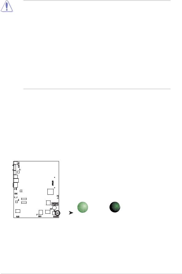
2.2Motherboard overview
Before you install the motherboard, study the configuration of your chassis to ensure that the motherboard fits into it. Refer to the chassis documentation before installing the motherboard.
Make sure to unplug the power cord before installing or removing the motherboard. Failure to do so can cause you physical injury and damage motherboard components.
2.2.1Placement direction
When installing the motherboard, make sure that you place it into the chassis in the correct orientation. The edge with external ports goes to the rear part of the chassis as indicated in the image below.
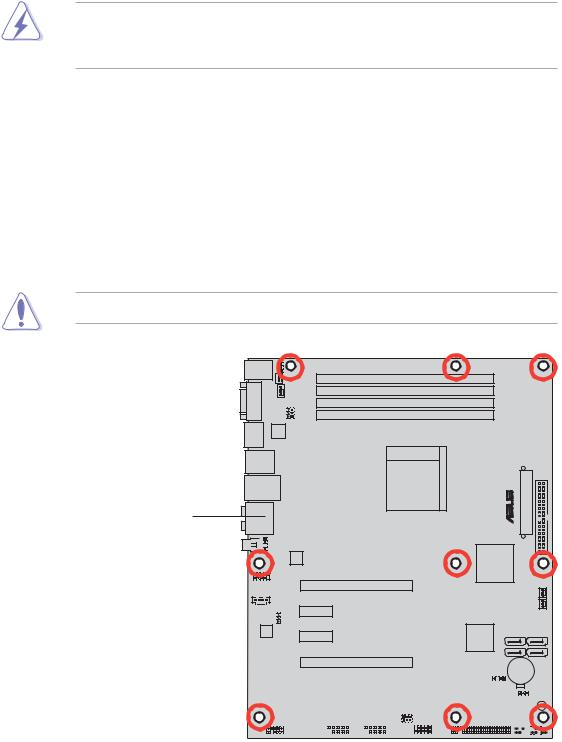
2.2.2Screw holes
Place nine (9) screws into the holes indicated by circles to secure the motherboard to the chassis.
Do not overtighten the screws! Doing so can damage the motherboard.
®
Place this side towards the rear of the chassis
M2R32-MVP
|
|
|
|
|
|
|
|
|
|
|
|
|
|
|
|
|
|
|
|
|
|
|
|
|
|
|
|
|
|
|
|
|
|
|
|
|
|
|
|
|
|
|
|
|
|
|
|
|
|
|
|
|
|
|
|
|
|
|
|
|
|
|
|
|
|
|
|
|
|
|
|
|
|
|
|
|
|
|
|
|
|
|
|
|
|
|
|
|
|
|
|
|
|
|
|
|
|
|
|
|
|
|
|
|
|
|
|
|
|
|
|
|
|
|
|
|
|
|
|
|
|
|
|
|
|
|
|
|
|
|
|
|
|
|
|
|
|
|
|
|
|
|
|
|
|
|
|
|
|
|
|
|
|
|
|
|
|
|
|
|
|
|
|
|
|
|
|
|
|
|
|
|
|
|
|
|
|
|
|
|
|
|
|
|
|
|
|
|
|
|
|
|
|
|
|
|
|
|
|
|
|
|
|
|
|
|
|
|
|
|
|
|
|
|
|
2 - 2 |
|
|
Chapter 2: Hardware information |
||||||||||||||||||||

2.2.3Motherboard layout
24.5cm (9.6in)
|
PS/2KBMS |
|
|
|
|
|
KBPWR1 |
||||||
|
T: Mouse |
|
|
|
|
|
|
|
|
|
|||
|
|
|
|
|
|
|
|
|
|
||||
|
B: Keyboard |
|
|
|
|
CHA_FAN2 |
|||||||
|
|
|
|
|
|
|
|
|
|||||
|
|
COM1 |
|
|
|
|
|
|
|
CPU_FAN |
|||
|
|
|
|
|
|
|
|
||||||
|
|
|
|
|
|
|
|
|
|
|
USBPW12 USBPW34 |
||
|
|
|
|
|
|||||||||
|
|
|
|
|
|
|
|
|
|
|
|||
|
|
|
|
|
|
|
|
|
|
|
|||
|
|
|
|
|
|||||||||
|
|
ESATA |
|
|
|
|
|
||||||
|
|
|
JMB360 |
||||||||||
|
|
|
|
|
|
|
|
|
|
|
|
|
|
F_USB12
 LAN_USB34
AUDIO


 SPDIF_OUT
SPDIF_O1
ATX12V
 USB910


 CD
CD
DDR2 DIMM_B2 (64 bit,240-pin module)
DDR2 DIMM_A2 (64 bit,240-pin module)
DDR2 DIMM_B1 (64 bit,240-pin module)
DDR2 DIMM_A1 (64 bit,240-pin module)
Socket AM2
PCIEX16_1
PRI_IDE
® |
EATXPWR |
PWR_FAN
|
|
|
|
|
|
|
|
|
|
PCIEX1_1 |
|
|
|
|
|
|
|
|
|
|
|
|
|
|
|
|
|
|
|
|
|
|
|
|
|
|
|
|
|
|
|
|
|
|
|
|
|
|
|
|
|
|
|
|
|
|
|
|
|
|
|
|
|
|
|
|
|
|
|
|
|
|
|
|
|
|
|
|
|
|
|
|
|
|
|
|
|
|
|
|
|
|
|
|
|
|
|
|
|
|
CHA_FAN1 |
||||||||||||
|
|
|
|
|
|
|
|
|
|
|
|
|
|
|
|
|
|
|
|
|
|
|
|
|
|
|
|
|
|
|
|
|
|
|
|
|
|
|
|
|
|
|
|
|||||||||||||
|
|
|
|
|
|
|
|
|
|
|
|
|
|
|
|
|
|
|
|
|
|
|
|
|
|
|
|
|
|
|
|
SATA2 SATA1 |
||||||||||||||||||||||||
|
|
|
|
|
|
|
|
|
|
|
|
|
|
|
|
|
|
|
|
|
|
|
|
|
|
|
|
|
|
|
|
|
|
|
|
|
|
|
|
|
|
|
|
|||||||||||||
|
|
|
|
|
USBPW910 |
|
|
|
|
|
|
|
|
|
|
|
|
|
|
|
|
|
|
|
|
|
|
|
|
|
||||||||||||||||||||||||||
|
|
|
|
|
|
|
|
|
|
|
|
|
|
|
|
|
|
|
|
|
|
|
|
|
|
|
|
|
|
|
|
|
|
|
|
|
|
|
|
|
|
|
|
SATA4 SATA3 |
||||||||||||
|
|
|
|
|
|
|
|
|
|
PCIEX1_2 |
|
|
|
|
|
|
|
|
|
|
|
|
|
|
|
|
|
|
|
|
|
|
|
|
|
|
|
|
|
|
|
|
||||||||||||||
|
|
|
|
|
|
|
|
|
|
|
|
|
|
|
|
|
|
|
|
|
|
|
|
|
|
|
|
|
|
|
|
|
|
|
|
|
|
|
|
|
|
|
|
|
|
|
|
|
|
|
|
|||||
AD1988A |
|
|
|
|
|
|
|
|
|
|
|
|
|
|
|
|
|
|
|
|
|
|
|
|
|
|
|
|
|
|
|
|
|
|
|
|
|
|
|
|||||||||||||||||
|
|
|
|
|
|
|
|
|
|
|
|
|
|
|
|
|
|
|
|
|
|
|
|
|
|
|
|
|
|
|
|
|
|
|
|
|
|
|
|
|
|
|
|
|
|
|
|
|
|
|
|
|
|
|
|
|
|
|
|
|
|
|
|
|
|
|
|
|
|
PCIEX16_2 |
|
|
|
|
|
|
|
|
|
|
|
|
|
|
|
|
|
|
|
|
|
|
|
|
|
CR2032 3V |
|
|
|
|
|
||||||||||||
|
|
|
|
|
|
|
|
|
|
|
|
|
|
|
|
|
|
|
|
|
|
|
|
|
|
|
|
|
|
|
|
|
|
|
|
|
|
|
|
|
|
|
|
|
|
|
|
|
||||||||
|
|
|
|
|
|
|
|
|
|
M2R32-MVP |
|
|
|
|
|
|
|
|
|
|
|
|
|
|
|
|
|
|
|
|
|
|
|
|
|
Lithium Cell |
|
|
|
|
|
|||||||||||||||
|
|
|
|
|
|
|
|
|
|
|
|
|
|
|
|
|
|
|
|
|
|
|
CHASSIS |
|
|
|
|
|
|
|
|
CMOS Power |
|
SB PWR |
||||||||||||||||||||||
|
Marvell |
|
|
|
|
|
PCI1 |
|
USBPW56 USBPW78 |
|
|
|
|
|
|
|
|
|
|
|
|
|
|
|
|
|
|
|
|
|
|
|
|
|
|
|
|
|
||||||||||||||||||
|
|
|
|
|
|
|
|
|
VIA VT6308P |
|
|
|
iTE |
|
|
CLRTC |
|
|
|
|
|
|
||||||||||||||||||||||||||||||||||
|
88E8001 |
|
|
|
|
|
|
|
|
|
|
|
|
|
|
|
|
IT8726F-S |
|
|
|
|
|
|
|
|
|
|
8Mb |
|
|
|||||||||||||||||||||||||
|
|
|
|
|
|
|
|
|
|
|
|
|
|
|
|
|
|
|
|
|
|
|
|
|
|
|
|
|
|
|
|
|
|
|
|
|||||||||||||||||||||
|
|
|
|
|
|
|
|
|
|
|
|
|
|
|
|
|
|
|
|
|
|
|
|
|
|
|
|
|
|
|
|
|
|
|
|
|
BIOS |
|
|
|||||||||||||||||
|
|
|
|
|
|
|
|
|
|
|
|
|
PCI2 |
|
|
|
|
|
|
|
|
|
|
|
|
|
|
|
|
|
|
|
||||||||||||||||||||||||
|
|
|
|
|
|
|
|
|
|
|
|
|
|
|
|
|
|
|
|
|
|
|
|
|
|
|
|
|
|
|
|
|||||||||||||||||||||||||
|
|
|
|
|
|
|
|
|
|
|
|
|
|
|
|
|
|
|
|
|
|
|
|
|
|
|
|
|
|
|
|
|
|
|
|
|
|
|
||||||||||||||||||
|
|
|
|
|
|
|
|
|
|
|
|
|
|
|
|
|
|
|
|
|
|
|
|
|
|
|
|
|
|
|
|
|
|
|
FLOPPY |
|
|
|
|
|
|
|
|
|
|
|
|
|
||||||||
|
|
AAFP |
|
|
|
|
|
|
|
|
|
|
|
|
|
|
USB56 |
|
|
|
|
|
|
|
|
|
|
|
PANEL |
|||||||||||||||||||||||||||
|
|
|
|
|
|
|
|
|
|
|
|
|
|
|
|
|
|
|
|
|
|
|
|
|
||||||||||||||||||||||||||||||||
|
|
|
|
|
|
|
|
|
|
|
|
|
|
|
|
|
|
|
|
|
|
|
|
|
||||||||||||||||||||||||||||||||
|
|
|
|
|
|
|
|
|
IE1394_2 |
|
|
|
|
|
|
|
|
USB78 |
|
|
|
|
|
|
|
|
|
|
|
|
|
|
|
|
|
|
|
|
|
|
|
|
|
|
|
|
|
|
|
|
|
|||||
30.5cm (12.0in)
ASUS M2R32-MVP |
2 - 3 |

2.2.4Layout Contents
S l o t s |
P a g e |
|
1. |
DDR DIMM slots |
2-11 |
2. |
PCI slots |
2-19 |
3. |
PCI Express x1 slots |
2-19 |
4. |
PCI Express x16 slots |
2-19 |
|
J u m p e r |
P a g e |
|
|
1. |
Clear RTC RAM (3-pin CLRTC) |
2-21 |
|
2. |
USB device wake-up (3-pin USBPW12, USBPW34, USBPW56, |
2-22 |
|
|
USBPW78, USBPW910) |
|
|
3. |
Keyboard power (3-pin KBPWR1) |
2-23 |
|
Rear panel connectors |
P a g e |
|
|
|
1. |
PS/2 mouse port (green) |
2-24 |
|
|
2. |
IEEEa 1394 port |
2-24 |
|
|
3. |
LAN (RJ-45) port |
2-24 |
|
|
4. |
Rear Speaker Out port (black) |
2-24 |
|
|
5. |
Center/Subwoofer port (orange) |
2-24 |
|
|
6. |
Line In port (light blue) |
2-24 |
|
|
7. |
Line Out port (lime) |
2-24 |
|
|
8. |
Coaxial S/PDIF Out port |
2-25 |
|
|
9. |
Microphone port (pink) |
2-25 |
|
|
10. |
Side Speaker Out port (gray) |
2-25 |
|
|
11. |
USB 2.0 ports 3 and 4 |
2-25 |
|
|
12. |
USB 2.0 ports 1 and 2 |
2-25 |
|
|
13. |
External SATA port |
2-25 |
|
|
14. |
Serial (COM) port |
2-25 |
|
|
15. |
PS/2 keyboard port (purple) |
2-25 |
|
2 - 4 |
Chapter 2: Hardware information |

Internal connectors |
P a g e |
|
||
1. |
Floppy disk drive connector (34-1 pin FLOPPY) |
2-26 |
|
|
2. |
IDE connectors (40-1 pin PRI_IDE) |
2-26 |
|
|
3. |
Serial ATA connectors (7-pin SATA1, SATA2, SATA3, SATA4) |
2-27 |
|
|
4. |
CPU, Chassis, and Power fan connectors |
2-29 |
|
|
|
(4-3 pin CPU_FAN, 3-pin CHA_FAN1, 3-pin CHA_FAN2, 3-pin PWR_FAN ) |
|
|
|
5. |
USB connectors (10-1 USB56, USB78, USB910) |
2-30 |
|
|
6. |
Power connectors (24-pin EATXPWR, 4-pin ATX12V) |
2-30 |
|
|
7. |
IEEE 1394a connectors (10-1 pin IE1394_2) |
2-31 |
|
|
8. |
Chassis intrusion connector (4-1 pin CHASSIS) |
2-32 |
|
|
9. |
Digital audio connector (4-1 pin SPDIF_OUT) |
2-32 |
|
|
10. |
Front panel audio connector (10-1 pin AAFP) |
2-33 |
|
|
11. |
Audio connector (4-pin CD [black]) |
2-33 |
|
|
12. |
System panel connector |
2-34 |
|
|
|
- |
System Power LED |
|
|
|
- |
Hard Disk activity |
|
|
|
- |
System warning speaker |
|
|
|
- |
Power/Soft-off button |
|
|
|
- |
Reset switch |
|
|
13. |
Q-Connector (System panel) |
2-35 |
|
|
ASUS M2R32-MVP |
2 - 5 |
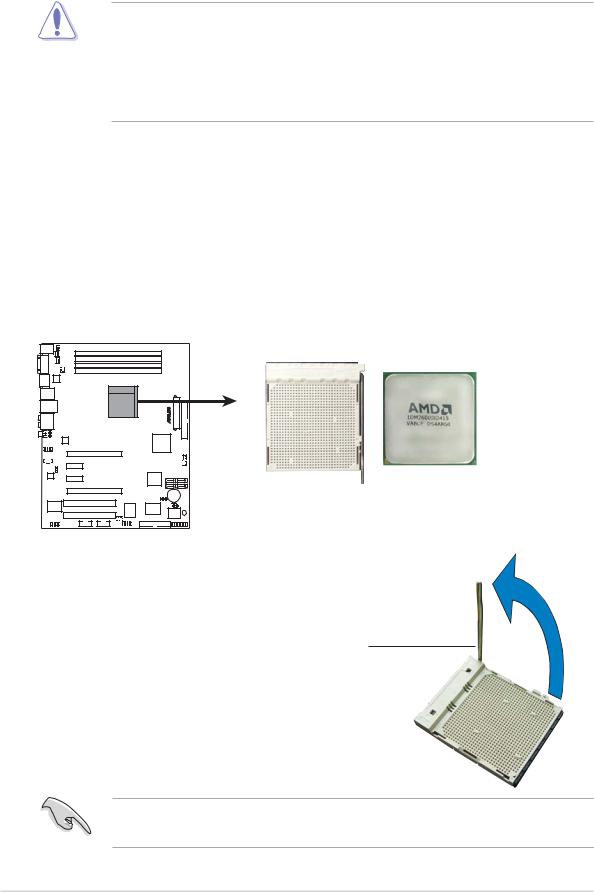
2.3Central Processing Unit (CPU)
The motherboard comes with a 940-pin AM2 socket designed for the AMD Athlon™ 64 X2/Athlon™ 64/Athlon™ FX/Sempron™ processor.
The AM2 socket has a different pinout from the 939-pin socket designed for the AMD Opteron™ processor. Make sure you use a CPU is designed for the AM2 socket. The CPU fits in only one correct orientation. DO NOT force the CPU into the socket to prevent bending the connectors on the socket and damaging the CPU!
2.3.1Installing the CPU
To install a CPU.
1.Locate the CPU socket on the motherboard.
M2R32-MVP
M2R32-MVP CPU Socket AM2
2.Unlock the socket by pressing the lever sideways, then lift it up to a 90°-100° angle.
Socke t lever
Make sure that the socket lever is lifted up to 90°-100° angle, otherwise the CPU does not fit in completely.
2 - 6 |
Chapter 2: Hardware information |
 Loading...