


M2N4-SLI
Motherboard

E2670
First Edition
July 2006
Copyright © 2006 ASUSTeK COMPUTER INC. All Rights Reserved.
No part of this manual, including the products and software described in it, may be reproduced, transmitted, transcribed, stored in a retrieval system, or translated into any language in any form or by any means, except documentation kept by the purchaser for backup purposes, without the express written permission of ASUSTeK COMPUTER INC. (“ASUS”).
Product warranty or service will not be extended if: (1) the product is repaired, modified or altered, unless such repair, modification of alteration is authorized in writing byASUS; or (2) the serial number of the product is defaced or missing.
ASUS PROVIDES THIS MANUAL “AS IS” WITHOUT WARRANTY OFANY KIND, EITHER EXPRESS OR IMPLIED, INCLUDING BUT NOT LIMITED TO THE IMPLIED WARRANTIES OR CONDITIONS OF MERCHANTABILITY OR FITNESS FORAPARTICULAR PURPOSE. IN NO EVENT SHALLASUS, ITS DIRECTORS, OFFICERS, EMPLOYEES ORAGENTS BE LIABLE FORANY INDIRECT, SPECIAL, INCIDENTAL, OR CONSEQUENTIAL DAMAGES (INCLUDING DAMAGES FOR LOSS OF PROFITS, LOSS OF BUSINESS, LOSS OF USE OR DATA, INTERRUPTION OF BUSINESSAND THE LIKE), EVEN IFASUS HAS BEEN ADVISED OF THE POSSIBILITY OF SUCH DAMAGESARISING FROMANY DEFECT OR ERROR IN THIS MANUAL OR PRODUCT.
SPECIFICATIONSAND INFORMATION CONTAINED IN THIS MANUALARE FURNISHED FOR INFORMATIONAL USE ONLY,ANDARE SUBJECT TO CHANGEATANY TIME WITHOUT NOTICE,AND SHOULD NOT BE CONSTRUEDASACOMMITMENT BY ASUS.ASUSASSUMES NO RESPONSIBILITY OR LIABILITY FORANY ERRORS OR INACCURACIES THAT MAYAPPEAR IN THIS MANUAL, INCLUDING THE PRODUCTS AND SOFTWARE DESCRIBED IN IT.
Products and corporate names appearing in this manual may or may not be registered trademarks or copyrights of their respective companies, and are used only for identification or explanation and to the owners’ benefit, without intent to infringe.
ii

Contents
Notices................................................................................................. |
vii |
Safety information.............................................................................. |
viii |
About this guide.................................................................................. |
ix |
Typography........................................................................................... |
x |
M2N4-SLI specifications summary....................................................... |
xi |
Chapter 1: Product introduction
1.1 |
Welcome!............................................................................... |
1-1 |
|
1.2 |
Package contents.................................................................. |
1-1 |
|
1.3 |
Special features..................................................................... |
1-2 |
|
|
1.3.1 |
Product highlights.................................................... |
1-2 |
|
1.3.2 |
ASUS Special features............................................. |
1-4 |
Chapter 2: Hardware information
2.1 |
Before you proceed............................................................... |
2-1 |
|
2.2 |
Motherboard overview........................................................... |
2-2 |
|
|
2.2.1 |
Placement direction................................................. |
2-2 |
|
2.2.2 |
Screw holes............................................................. |
2-2 |
|
2.2.3 |
Motherboard layout................................................. |
2-3 |
|
2.2.4 |
Layout Contents...................................................... |
2-4 |
2.3 |
Central Processing Unit (CPU)............................................... |
2-5 |
|
|
2.3.1 |
Installing the CPU..................................................... |
2-5 |
|
2.3.2 Installing the heatsink and fan................................. |
2-7 |
|
2.4 |
System memory.................................................................. |
2-10 |
|
|
2.4.1 |
Overview................................................................ |
2-10 |
|
2.4.2 |
Memory configurations.......................................... |
2-10 |
|
2.4.3 |
Installing a DIMM.................................................... |
2-15 |
|
2.4.4 |
Removing a DIMM................................................... |
2-15 |
2.5 |
Expansion slots.................................................................... |
2-16 |
|
|
2.5.1 Installing an expansion card................................... |
2-16 |
|
|
2.5.2 Configuring an expansion card............................... |
2-16 |
|
|
2.5.3 |
Interrupt assignments........................................... |
2-17 |
|
2.5.4 |
PCI slots................................................................. |
2-17 |
|
2.5.5 PCI Express x1 slot................................................ |
2-18 |
|
|
2.5.6 PCI Express x16 slots............................................ |
2-18 |
|
iii

Contents
2.6 |
Jumpers |
............................................................................... |
2-19 |
2.7 |
Connectors.......................................................................... |
2-22 |
|
|
2.7.1 |
Rear panel connectors ........................................... |
2-22 |
|
2.7.2 ................................................ |
Internal connectors |
2-24 |
Chapter 3: Powering up
3.1 |
Starting up for the first time................................................. |
3-1 |
|
3.2 |
Powering off the computer................................................... |
3-2 |
|
|
3.2.1 |
Using the OS shut down function............................ |
3-2 |
|
3.2.2 |
Using the dual function power switch..................... |
3-2 |
Chapter 4: BIOS setup
4.1 Managing and updating your BIOS......................................... |
4-1 |
||
|
4.1.1 Creating a bootable floppy disk............................... |
4-1 |
|
|
4.1.2 |
Updating the BIOS................................................... |
4-2 |
|
4.1.3 Saving the current BIOS file..................................... |
4-4 |
|
|
4.1.4 ASUS CrashFree BIOS 3 utility................................. |
4-5 |
|
|
4.1.5 ASUS EZ Flash 2 utility............................................ |
4-7 |
|
|
4.1.6 |
ASUS Update utility................................................. |
4-8 |
4.2 |
BIOS setup program............................................................ |
4-11 |
|
|
4.2.1 |
BIOS menu screen.................................................. |
4-12 |
|
4.2.2 |
Menu bar................................................................ |
4-12 |
|
4.2.3 |
Legend bar............................................................ |
4-13 |
|
4.2.4 |
Menu items............................................................ |
4-13 |
|
4.2.5 |
Sub-menu items..................................................... |
4-13 |
|
4.2.6 |
Configuration fields................................................ |
4-13 |
|
4.2.7 |
Pop-up window...................................................... |
4-14 |
|
4.2.8 |
General help........................................................... |
4-14 |
4.3 |
Main menu........................................................................... |
4-15 |
|
|
4.3.1 |
System Time ........................................................ |
4-15 |
|
4.3.2 |
System Date ......................................................... |
4-15 |
|
4.3.3 |
Legacy Diskette A ................................................ |
4-15 |
|
4.3.5 Primary and Secondary IDE Master/Slave.............. |
4-16 |
|
|
4.3.6 SATA 1, 2, 3, 4..................................................... |
4-18 |
|
|
4.3.7 |
HDD SMART Monitoring......................................... |
4-19 |
iv
Contents
|
4.3.8 |
Installed Memory................................................... |
4-19 |
4.4 |
Advanced menu................................................................... |
4-20 |
|
|
4.4.1 |
JumperFree Configuration..................................... |
4-20 |
|
4.4.3 |
CPU Configuration.................................................. |
4-23 |
|
4.4.4 |
PCIPnP.................................................................... |
4-25 |
|
4.4.5 |
Onboard Device Configuration............................... |
4-26 |
|
4.4.6 |
SLI Configuration................................................... |
4-31 |
4.5 |
Power menu......................................................................... |
4-32 |
|
|
4.5.1 |
ACPI Suspend Type .............................................. |
4-32 |
|
4.5.2 |
ACPI APIC Support ................................................ |
4-32 |
|
4.5.3 |
APM Configuration................................................. |
4-33 |
|
4.5.4 |
Hardware Monitor.................................................. |
4-35 |
4.6 |
Boot menu........................................................................... |
4-37 |
|
|
4.6.1 |
Boot Device Priority............................................... |
4-37 |
|
4.6.2 |
Removable Drives.................................................. |
4-38 |
|
4.6.3 |
Hard Disk Drives.................................................... |
4-38 |
|
4.6.4 |
Boot Settings Configuration ................................. |
4-39 |
|
4.6.5 |
Security................................................................. |
4-41 |
4.7 |
Tools menu.......................................................................... |
4-43 |
|
|
ASUS EZ Flash 2.................................................................. |
4-43 |
|
4.8 |
Exit menu............................................................................ |
4-44 |
|
Chapter 5: Software support
5.1 |
Installing an operating system.............................................. |
5-1 |
|
5.2 |
Support CD information......................................................... |
5-1 |
|
|
5.2.1 Running the support CD.......................................... |
5-1 |
|
|
5.2.2 |
Drivers menu........................................................... |
5-2 |
|
5.2.3 |
Utilities menu........................................................... |
5-3 |
|
5.2.4 |
Manuals menu.......................................................... |
5-4 |
|
5.2.5 |
ASUS Contact information....................................... |
5-5 |
|
5.2.6 |
Other information.................................................... |
5-5 |
5.3 |
Software information............................................................. |
5-8 |
|
|
5.3.1 Cool ‘n’ Quiet!™ Technology.................................... |
5-8 |
|
|
5.3.2 ASUS PC Probe II.................................................... |
5-10 |
|
5.4 |
RAID configurations............................................................. |
5-16 |
|
|
|
|
|

Contents
|
5.4.1 |
Installing hard disks............................................... |
5-17 |
|
5.4.2 |
NVIDIA® RAID configurations................................. |
5-18 |
5.5 |
Creating a RAID driver disk.................................................. |
5-25 |
|
Chapter 6: NVIDIA® SLI™ technology support
6.1 |
Overview................................................................................ |
6-1 |
|
Requirements........................................................................ |
6-1 |
6.2 |
Dual graphics card setup....................................................... |
6-2 |
|
6.2.1 Installing SLI-ready graphics cards.......................... |
6-2 |
|
6.2.2 Installing the device drivers..................................... |
6-5 |
|
6.2.3 Enabling the multi-GPU feature in Windows............. |
6-5 |
vi

Notices
Federal Communications Commission Statement
This device complies with Part 15 of the FCC Rules. Operation is subject to the following two conditions:
•This device may not cause harmful interference, and
•This device must accept any interference received including interference that may cause undesired operation.
This equipment has been tested and found to comply with the limits for a Class B digital device, pursuant to Part 15 of the FCC Rules. These limits are designed to provide reasonable protection against harmful interference in a residential installation. This equipment generates, uses and can radiate radio frequency energy and, if not installed and used in accordance with manufacturer’s instructions, may cause harmful interference to radio communications. However, there is no guarantee that interference will
not occur in a particular installation. If this equipment does cause harmful interference to radio or television reception, which can be determined by turning the equipment off and on, the user is encouraged to try to correct the interference by one or more of the following measures:
•Reorient or relocate the receiving antenna.
•Increase the separation between the equipment and receiver.
•Connect the equipment to an outlet on a circuit different from that to which the receiver is connected.
•Consult the dealer or an experienced radio/TV technician for help.
The use of shielded cables for connection of the monitor to the graphics card is required to assure compliance with FCC regulations. Changes
or modifications to this unit not expressly approved by the party responsible for compliance could void the user’s authority to operate this equipment.
Canadian Department of Communications Statement
This digital apparatus does not exceed the Class B limits for radio noise emissions from digital apparatus set out in the Radio Interference Regulations of the Canadian Department of Communications.
This class B digital apparatus complies with Canadian ICES-003.
vii
Safety information
Electrical safety
•To prevent electrical shock hazard, disconnect the power cable from the electrical outlet before relocating the system.
•When adding or removing devices to or from the system, ensure that the power cables for the devices are unplugged before the signal cables are connected. If possible, disconnect all power cables from the existing system before you add a device.
•Before connecting or removing signal cables from the motherboard, ensure that all power cables are unplugged.
•Seek professional assistance before using an adapter or extension cord. These devices could interrupt the grounding circuit.
•Make sure that your power supply is set to the correct voltage in your area. If you are not sure about the voltage of the electrical outlet you are using, contact your local power company.
•If the power supply is broken, do not try to fix it by yourself. Contact a qualified service technician or your retailer.
Operation safety
•Before installing the motherboard and adding devices on it, carefully read all the manuals that came with the package.
•Before using the product, make sure all cables are correctly connected and the power cables are not damaged. If you detect any damage, contact your dealer immediately.
•To avoid short circuits, keep paper clips, screws, and staples away from connectors, slots, sockets and circuitry.
•Avoid dust, humidity, and temperature extremes. Do not place the product in any area where it may become wet.
•Place the product on a stable surface.
•If you encounter technical problems with the product, contact a qualified service technician or your retailer.
The symbol of the crossed out wheeled bin indicates that the product (electrical and electronic equipment) should not be placed in municipal waste. Check local regulations for disposal of electronic products.
viii

About this guide
This user guide contains the information you need when installing and configuring the motherboard.
How this guide is organized
This manual contains the following parts:
•Chapter 1: Product introduction
This chapter describes the features of the motherboard and the new technology it supports.
•Chapter 2: Hardware information
This chapter lists the hardware setup procedures that you have to perform when installing system components. It includes description of the switches, jumpers, and connectors on the motherboard.
•Chapter 3: Powering up
This chapter describes the power up sequence, the vocal POST messages, and ways of shutting down the system.
•Chapter 4: BIOS setup
This chapter tells how to change system settings through the BIOS Setup menus. Detailed descriptions of the BIOS parameters are also provided.
•Chapter 5: Software support
This chapter describes the contents of the support CD that comes with the motherboard package.
•Chapter 6: NVIDIA® SLI™ technology support
This chapter tells how to install SLI-ready PCI Express graphics cards.
ix

Where to find more information
Refer to the following sources for additional information and for product and software updates.
1.ASUS websites
The ASUS website provides updated information on ASUS hardware and software products. Refer to the ASUS contact information.
2.Optional documentation
Your product package may include optional documentation, such as warranty flyers, that may have been added by your dealer. These documents are not part of the standard package.
Conventions used in this guide
To make sure that you perform certain tasks properly, take note of the following symbols used throughout this manual.
DANGER/WARNING: Information to prevent injury to yourself when trying to complete a task.
CAUTION: Information to prevent damage to the components when trying to complete a task.
IMPORTANT: Instructions that you MUST follow to complete a task.
NOTE: Tips and additional information to help you complete a task.
Typography
Bold text |
Indicates a menu or an item to select |
Italics |
Used to emphasize a word or a phrase |
<Key> |
Keys enclosed in the less-than and greater-than sign means |
|
that you must press the enclosed key |
|
Example: <Enter> means that you must press the Enter or |
|
Return key |
<Key1>+<Key2>+<Key3> |
If you must press two or more keys simultaneously, the |
|
key names are linked with a plus sign (+) |
|
Example: <Ctrl>+<Alt>+<D> |
Command |
Means that you must type the command exactly as shown, |
|
then supply the required item or value enclosed in |
|
brackets |
|
Example: At the DOS prompt, type the command line: |
|
awdflash M2N4SLI.ROM |
|
|
M2N4-SLI specifications summary
CPU
Chipset
System bus
Memory
Expansion slots
Scalable Link Interface (SLI™)
Storage
LAN
SocketAM2 forAMDAthlon™ 64 FX/AMDAthlon™ 64 X2 /AMDAthlon 64™/AMD Sempron™ processors
SupportsAMD Cool ‘n’ Quiet™ Technology
AMD64 architecture enables simultaneous 32-bit and 64-bit computing
AMD Live!™ ready
NVIDIA® nForce® 4 SLI™ MCP
2000 / 1600 MT/s
Dual-channel memory architecture
- 4 x 240-pin DIMM sockets support unbuffered ECC/non-ECC DDR2 800/667/533 MHz memory modules
- Supports up to 8 GB system memory
2 x PCI Express™ x16 slots
Supports NVIDIA® SLI™ Technology (both at x8 mode) 2 x PCI Express™ x1 slots
2 x PCI 2.2 slots
Supports two identical NVIDIA® SLI™-ready graphics card ASUS two-slot thermal design
NVIDIA® nForce® 4 SLI™ MCP supports:
- 2 x IDE connector for up to four Ultra DMA 133/100/66/33 devices
- 4 x SerialATA3.0 Gb/s connectors support four SerialATAdevices
- RAID 0, RAID 1, RAID 0+1, RAID 5, and JBOD configurations spanning across SerialATAdrives
NVIDIA® nForce® 4 SLI™ MCP built-in Gigabit MAC with externalAttansic PHY
Supports TCP/IPAcceleration
|
Audio |
Realtek® ALC850 6-channelAC’97 CODEC |
|
|
|
Supports Jack-Sensing and Enumeration Technology |
|
|
|
Supports S/PDIF Out interface |
|
|
USB 2.0 |
Supports up to 10 USB 2.0/1.1 ports (six at mid-board, |
|
|
|
four on the rear panel) |
|
|
ASUS Exclusive |
AI Overclocking (intelligent CPU frequency tuner) |
|
|
Overclocking features |
Stepless Frequency Selection(SFS) allows FSB tuning |
|
|
|
from 200 MHz up to 400 MHz at 1 MHz increment |
|
|
|
ASUS C.P.R. (CPU Parameter Recall) |
|
|
|
Adjustable FSB/DDR2 ratio. Fixed PCI/PCIe frequencies |
|
|
|
(continued on the next page) |
|
xi
M2N4-SLI specifications summary
Special features
Rear panel
Internal connectors
BIOS features
Manageability
Power requirements
Support CD contents
Form factor
ASUS EZ DIY:
- Q-Connector
- ASUS CrashFree BIOS 3
- ASUS EZ Flash 2
ASUS Q-Fan 2
ASUS MyLogo2
1 x Parallel port
1 x PS/2 keyboard port (purple)
1 x PS/2 mouse port (green)
1 x Serial (COM1) port
1 x Coaxial S/PDIF Out port
1 x LAN (RJ-45) ports
4 x USB 2.0/1.1 ports
6-channel audio ports
3 x USB 2.0 connectors support six additional USB 2.0 ports
1 x Floppy disk drive connector
2 x IDE connector for four devices
4 x SerialATAconnectors
1 x CPU / 1 x Chassis / 1 x Power fan connectors S/PDIF out connector
Front panel audio connector CD/AUX audio in connectors 24-pinATX power connector 4-pinATX 12 V power connector System panel connector
4 Mb BIOS ROM,AWARD BIOS, PnP, DMI 2.0, WfM2.0,
SM BIOS 2.3
WOL by PME, WOR by PME, Chassis intrusion, PXE
ATX power supply with 24-pin and 4-pin 12V plugs ATX 12V 2.0 compliant
Device drivers
ASUS PC Probe II
ASUS Update
NVIDIA® MediaShield™ RAID
Anti-virus software (OEM version)
ATX form factor: 12 in x 9 in (30.5 cm x 22.8 cm)
*Specifications are subject to change without notice.
xii
This chapter describes the motherboard |
1 |
|
|
||
features and the new technologies |
|
|
it supports. |
|
Product |
|
|
|
|
introduction |
|

Chapter summary
1.1 |
Welcome!............................................................................... |
1-1 |
1.2 |
Package contents.................................................................. |
1-1 |
1.3 |
Special features..................................................................... |
1-2 |
ASUS M2N4-SLI
1.1Welcome!
Thank you for buying an ASUS® M2N4-SLI
 motherboard!
The motherboard delivers a host of new features and latest technologies, making it another standout in the long line of ASUS quality motherboards!
Before you start installing the motherboard, and hardware devices on it, check the items in your package with the list below.
1.2Package contents
Check your motherboard package for the following items.
Motherboard |
ASUS M2N4-SLI motherboard |
Cables |
2 x Serial ATA signal cables |
|
1 x Serial ATA power cable with dual plugs |
|
1 x Ultra DMA/133 cable |
|
1 x Floppy disk drive cable |
Accessories |
I/O shield |
|
ASUS SLI™ bridge |
|
1 x ASUS Q-Connector Kit |
|
(USB, System panel; Retail version only) |
Application CDs |
ASUS motherboard support CD |
Documentation |
User guide |
If any of the above items is damaged or missing, contact your retailer.
ASUS M2N4-SLI |
1- |

1.3Special features
1.3.1Product highlights
Latest processor technology
The motherboard comes with a 940-pin AM2 socket that supports AMD
Athlon™ 64 X2/AMD Athlon™ 64/AMD Athlon™ 64 FX/AMD Sempron™ processors. With an integrated low-latency high-bandwidth memory controller and a highly scalable HyperTransport™ technology-based system bus, the motherboard provides a powerful platform for your diverse computing needs, increased office productivity, and enhanced digital media experience. See page 2-5 for details.
Scalable Link Interface (SLI™) technology 
The NVIDIA® nForce4® Scalable Link Interface (SLI™) technology allows two graphics processing units (GPUs) in a single system. This technology takes advantage of the PCI Express™ bus architecture and features intelligent hardware and software solutions that allows multiple GPUs to work together and achieve exceptional graphics performance. See Chapter 6 for details.
AMD Cool ‘n’ Quiet!™ Technology 
The motherboard supports the AMD Cool ‘n’ Quiet!™ Technology that dynamically and automatically changes the CPU speed, voltage and amount of power depending on the task the CPU performs. See pages 4-25, 5 3 and 5-9.
Gigabit LAN 
The motherboard comes with a Gigabit LAN controller built into the NVIDIA® nForce™4 chipset to meet your growing networking needs. The controller uses the PCI Express segment to provide faster data bandwidth for your Internet, LAN, and file sharing requirements. See page 2-22 for details.
DDR2 memory support 


The motherboard supports DDR2 memory that features data transfer rates of 800/667/533 MHz to meet the higher bandwidth requirements of the latest 3D graphics, multimedia, and Internet applications. The dual-channel DDR2 architecture doubles the bandwidth of your system memory to boost system performance, eliminating bottlenecks with peak bandwidths of up to 12.8 GB/s. See pages 210 to 2-13 for details.
1- |
Chapter 1: Product introduction |

Serial ATA 3Gb/s RAID 

The motherboard supports the next-generation Serial ATA hard drives based on the SATA 3Gb/s storage specification. The onboard NVIDIA nForce® 4 SLI™ MCP allows RAID 0, RAID 1, RAID 0+1, RAID 5, and JBOD.
See page 2 25.
PCI Express™ interface 
The motherboard fully supports PCI Express, the latest I/O interconnect technology that speeds up the PCI bus. PCI Express features point topoint serial interconnections between devices and allows higher clockspeeds by carrying data in packets. This high speed interface is software compatible with existing PCI specifications. See page 2-18 for details.
S/PDIF digital sound ready 
The motherboard supports the S/PDIF Out function through the S/PDIF interfaces on the rear panel. The S/PDIF technology turns your computer into a high-end entertainment system with digital connectivity to powerful audio and speaker systems. See page 2-23 for details.
USB 2.0 technology 
The motherboard implements the Universal Serial Bus (USB) 2.0 specification, dramatically increasing the connection speed from the
12 Mbps bandwidth on USB 1.1 to a fast 480 Mbps on USB 2.0. USB 2.0 is backward compatible with USB 1.1. See page 2-23 and 2-27 for details.
ASUS M2N4-SLI |
1- |

1.3.2ASUS Special features
ASUS Two-slot thermal design
The motherboard is designed with two PCI Express x1 slots placed between the PCI Express x16 slots allowing an increase in airflow between the two
PCI Express x16 graphics cards. This special design permits more room for ventilation thus lowering the overall system temperature.
ASUS CrashFree BIOS 3
The ASUS CrashFree BIOS 3 allows users to restore corrupted BIOS data from a USB flash disk containing the BIOS file. This utility saves users the cost and hassle of buying a replacement BIOS chip. See page 4-5 for details.
ASUS EZ Flash 2
EZ Flash 2 is a user-friendly BIOS update utility. Simply press the predefined hotkey to launch the utility and update the BIOS without entering the OS. Update your BIOS easily without preparing a bootable diskette or using an
OS-based flash utility. See page 4-7 for details.
ASUS Q-Connector 
ASUS Q-Connector allows you to easily connect or disconnect the chassis front panel cables to the motherboard. This unique module eliminates the trouble of connecting the system panel cables one at a time and avoiding wrong cable connections.
ASUS Q-Fan 2 technology 
The ASUS Q-Fan technology smartly adjusts the CPU and chassis fan speeds according to the system loading to ensure quiet, cool, and efficient operation. See page 4-35 for details.
ASUS MyLogo2™ 
This new feature present in the motherboard allows you to personalize and add style to your system with customizable boot logos.
1- |
Chapter 1: Product introduction |
This chapter lists the hardware setup procedures that you have to perform when installing system components. It includes description of the jumpers and connectors on the motherboard.
Hardware2 information

Chapter summary
2.1 |
Before you proceed............................................................... |
2-1 |
2.2 |
Motherboard overview........................................................... |
2-2 |
2.3 |
Central Processing Unit (CPU)............................................... |
2-5 |
2.4 |
System memory.................................................................. |
2-10 |
2.5 |
Expansion slots.................................................................... |
2-16 |
2.6 |
Jumpers............................................................................... |
2-19 |
2.7 |
Connectors.......................................................................... |
2-22 |
ASUS M2N4-SLI
2.1Before you proceed
Take note of the following precautions before you install motherboard components or change any motherboard settings.
•Make sure that your power supply unit (PSU) can provide at least the minimum power required by your system. See “8. ATX power connectors” on page 2-26 for details.
•Unplug the power cord from the wall socket before touching any component.
•Use a grounded wrist strap or touch a safely grounded object or to a metal object, such as the power supply case, before handling components to avoid damaging them due to static electricity
•Hold components by the edges to avoid touching the ICs on them.
•Whenever you uninstall any component, place it on a grounded antistatic pad or in the bag that came with the component.
•Before you install or remove any component, ensure that the ATX power supply is switched off or the power cord is detached from the power supply. Failure to do so may cause severe damage to the motherboard, peripherals, and/or components.
Onboard LED
The motherboard comes with a standby power LED that lights up to indicate that the system is ON, in sleep mode, or in soft-off mode. This is a reminder that you should shut down the system and unplug the power cable before removing or plugging in any motherboard component. The illustration below shows the location of the onboard LED.
M2N4-SLI |
|
SB_PWR |
|
ON |
OFF |
Standby |
Powered |
Power |
Off |
M2N4-SLI Onboard LED
ASUS M2N4-SLI |
2- |
2.2Motherboard overview
Before you install the motherboard, study the configuration of your chassis to ensure that the motherboard fits into it.
Make sure to unplug the power cord before installing or removing the motherboard. Failure to do so can cause you physical injury and damage motherboard components.
2.2.1Placement direction
When installing the motherboard, make sure that you place it into the chassis in the correct orientation. The edge with external ports goes to the rear part of the chassis as indicated in the image below.
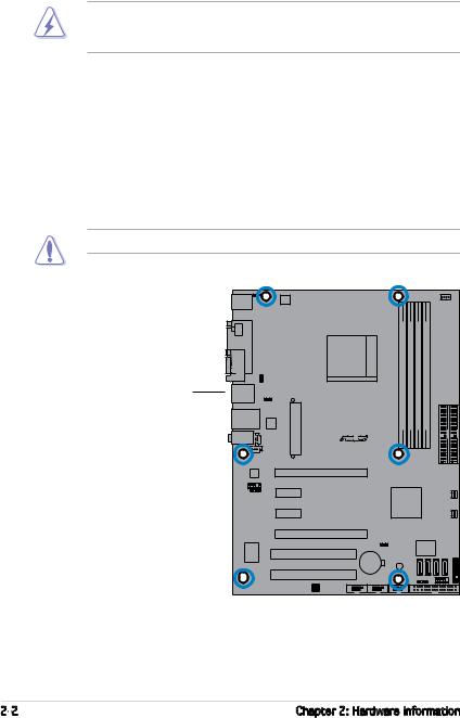
2.2.2Screw holes
Place six (6) screws into the holes indicated by circles to secure the motherboard to the chassis.
Do not overtighten the screws! Doing so can damage the motherboard.
Place this side towards the rear of the chassis
M2N4-SLI |
R |
2- |
Chapter 2: Hardware information |
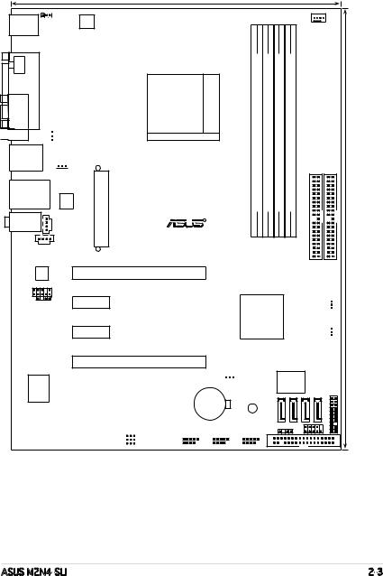
2.2.3Motherboard layout
23.0cm (9.0in)
PS/2KBMS |
KBPWR |
T: Mouse |
ATX12V |
B: Keyboard |
|
SPDIF O1 |
PORT |
|
PARALLEL |

 COM1
COM1
USB12
Socket AM2
 USBPW12


 USBPW34
LAN_USB34 |
CD |
EATXPWR |
|
|
Attansic |
|
M2N4-SLI |
|
F1 |
|
|
AUDIO |
|
|
R |
AUX
ALC850
PCIEX16_1
FP_AUDIO
SPDIF_OUT PCIEX1_1
PCIEX1_2
|
|
|
CPU_FAN |
|
DDR2 DIMM A1 (64 bit,240-pin module) |
DDR2 DIMM B1 (64 bit,240-pin module) DDR2 DIMM A2 (64 bit,240-pin module) |
DDR2 DIMM B2 (64 bit,240-pin module) |
|
(12.0in) |
|
|
SEC IDE |
PRI IDE |
|
|
|
|
|
30.5cm |


 FAN_PWR NVIDIA NF4 SLI


 FAN_CHA
Super I/O
PCIEX16_2
CLRTC
PCI1 |
|
|
|
|
CR2032 3V |
|
|
|
|||||||
|
|
|
|
|
|
|
|
|
SB_PWR |
||||||
|
|
|
|
|
|
|
|
|
Lithium Cell |
||||||
|
|
|
|
|
|
|
|
CMOS Power |
|
|
|
||||
PCI2 |
|
|
|
|
|
|
|
|
|
|
|
||||
|
|
|
|
USBPW56 |
USB56 |
|
USB78 |
USB910 |
|||||||
|
|
|
|
USBPW78 |
|
|
|
|
|
|
|
|
|
|
|
|
|
|
|
USBPW910 |
|
|
|
|
|
|
|
|
|
|
|
4Mb BIOS
SATA1 |
SATA2 |
SATA3 |
SATA4 |
PANEL |
CHASSIS |
|
F_PANEL |
|
|
|
|
|
|
|
|
FLOPPY |
|
|
|
ASUS M2N4-SLI |
2- |
2.2.4Layout Contents
|
|
Slots |
Page |
|
|
|
|
1. DDR2 DIMM slots |
2-10 |
|
|
|
|
|
|||
|
|
2. PCI slots |
2-17 |
|
|
|
|
3. PCI Express x16 slot |
2-18 |
|
|
|
|
4. PCI Express x1 slot |
2-18 |
|
|
|
|
|
|
||
|
|
Slots |
Page |
|
|
|
|
1. CLRTC (3-pin CLRTC1) |
2-19 |
|
|
|
|
2. USB device wake-up (3-pin USBPW12, USBPW34, USBPW56, |
|
|
|
|
|
|
USBPW78, USBPW910) |
2-20 |
|
|
|
3. Keyboard Power (3-pin KBPWR) |
2-21 |
|
|
|
|
Rear panel connectors |
Page |
||
|
|
1. |
PS/2 mouse port (green) |
2-22 |
|
|
|
|
|||
|
|
2. |
Parallel port |
2-22 |
|
|
|
3. |
Serial (COM) port |
2-22 |
|
|
|
4. |
LAN (RJ-45) port |
2-22 |
|
|
|
5. |
Line In port (light blue) |
2-22 |
|
|
|
6. |
Microphone port (pink) |
2-22 |
|
|
|
7. |
Line Out port (lime) |
2-22 |
|
|
|
8. |
USB 2.0 ports 3 and 4 |
2-23 |
|
|
|
9. |
USB 2.0 ports 1 and 2 |
2-23 |
|
|
|
10. Coaxial S/PDIF out port |
2-23 |
|
|
|
|
11. PS/2 keyboard port (purple) |
2-23 |
|
|
|
|
|
|
|
|
|
|
Internal connectors |
Page |
|
|
|
|
1. Floppy disk drive connector (34-1 pin FLOPPY) |
2-23 |
|
|
|
|
2. Primary/Secondary IDE connector (40-1 pin PRI_IDE, SEC_IDE) |
2-24 |
|
|
|
|
3. nForce 4 Serial ATA connectors (7-pin SATA1, SATA2, SATA3, SATA4) |
2-25 |
|
|
|
|
4. CPU fan connector (3-pin CPU_FAN) |
2-26 |
|
|
|
|
5. Power fan connector (3-pin PWR_FAN) |
2-26 |
|
|
|
|
6. Chassis fan connector (3-pin CHA_FAN) |
2-26 |
|
|
|
|
7. USB headers (10-1 USB56, USB78, USB910) |
2-27 |
|
|
|
|
8. ATX power connector (24-pin EATXPWR1) |
2-28 |
|
|
|
|
9. ATX 12V power connector (4-pin ATX12V1) |
2-28 |
|
|
|
|
10. Internal audio connectors (4-pin CD/AUX) |
2-29 |
|
|
|
|
11. Front panel audio connector (10-1 pin FP_AUDIO) |
2-29 |
|
|
|
|
12. System panel connector (20-8 pin PANEL) |
2-30 |
|
|
•System power LED (2-pin LED)
•Hard disk drive activity LED (2-pin IDE_LED)
•System warning speaker (4-pin SPEAKER)
•ATX power button/soft-off button (2-pin PWR)
•Reset button (2-pin RESET)
2- |
Chapter 2: Hardware information |
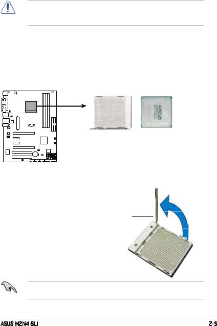
2.3Central Processing Unit (CPU)
The motherboard comes with a 940-pin AM2 socket designed for the AMD
Athlon™ 64 X2/AMD Athlon™ 64 FX/AMD Athlon™ 64 and AMD Sempron™ processors.
Make sure you use a CPU is designed for the AM2 socket. The CPU fits in only one correct orientation. DO NOT force the CPU into the socket to prevent bending the connectors on the socket and damaging the CPU!
2.3.1Installing the CPU
To install a CPU:
1.Locate the CPU socket on the motherboard.
M2N4-SLI |
M2N4-SLI CPU Socket AM2
2.Unlock the socket by pressing the lever sideways, then lift it up to a 90º angle.
Socket lever
Make sure that the socket lever is lifted up to a 90º angle; otherwise, the CPU will not fit in completely.
ASUS M2N4-SLI |
2- |
3.Position the CPU above the socket such that the CPU corner with the gold triangle matches the socket corner with a small triangle.
Gold triangle
Small triangle
5.When the CPU is in place, push down the socket lever to secure the CPU. The lever clicks on the side tab to indicate that it is locked.
6.Install a CPU heatsink and fan following the instructions that came with the heatsink package.
2- |
Chapter 2: Hardware information |
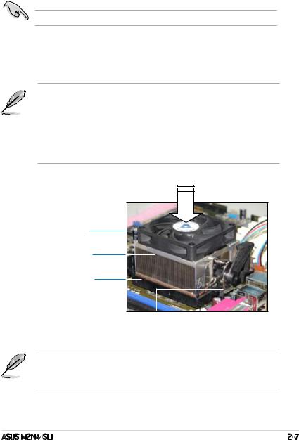
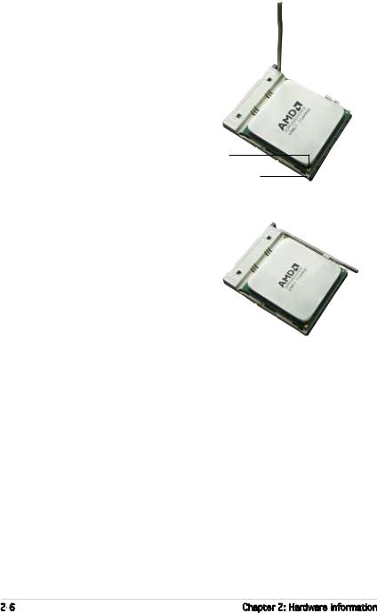
2.3.2Installing the heatsink and fan
The the AMD Athlon™ FX, AMD Athlon 64™, AMD Sempron™ or AMD Athlon™ X2 processor require a specially designed heatsink and fan assembly to ensure optimum thermal condition and performance.
Make sure that you use only qualified heatsink and fan assembly.
Follow these steps to install the CPU heatsink and fan.
1.Place the heatsink on top of the installed CPU, making sure that the heatsink fits properly on the retention module base.
•The retention module base is already installed on the motherboard
upon purchase.
• You do not have to remove the retention module base when installing the CPU or installing other motherboard components.
•If you purchased a separate CPU heatsink and fan assembly, make sure that a Thermal Interface Material is properly applied to the CPU heatsink or CPU before you install the heatsink and fan assembly.
CPU Fan
CPU Heatsink
Retention Module Base
|
|
|
|
Retention bracket |
Retention bracket |
lock |
|
Your boxed CPU heatsink and fan assembly should come with installation instructions for the CPU, heatsink, and the retention mechanism. If the instructions in this section do not match the CPU documentation, follow the latter.
ASUS M2N4-SLI |
2- |

2.Attach one end of the retention bracket to the retention module base.
3.Align the other end of the retention bracket (near the retention bracket lock) to the retention module base. A clicking sound denotes that the retention bracket is in place.
Make sure that the fan and heatsink assembly perfectly fits the retention mechanism module base, otherwise you cannot snap the retention bracket in place.
4.Push down the retention bracket lock on the retention mechanism to secure the heatsink and fan to the module base.
2- |
Chapter 2: Hardware information |
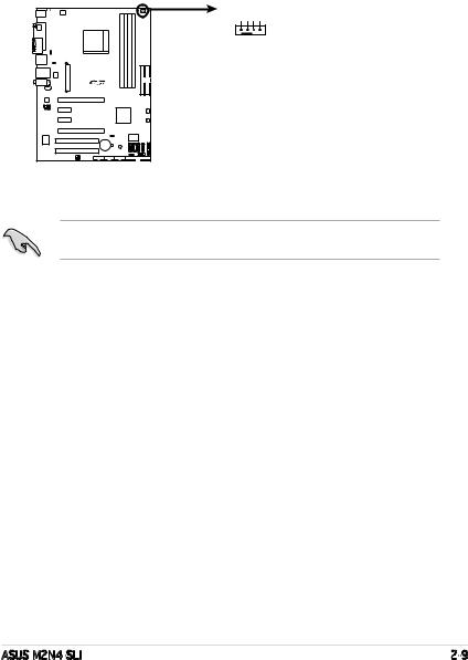
5.When the fan and heatsink assembly is in place, connect the CPU fan cable to the connector on the motherboard labeled CPU_FAN.
CPU_FAN
PWRFAN INFAN PWMFAN
GNDCPUCPUCPU
M2N4-SLI
M2N4-SLI CPU Fan Connectors
Do not forget to connect the CPU fan connector! Hardware monitoring errors can occur if you fail to plug this connector.
ASUS M2N4-SLI |
2- |
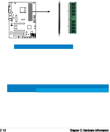
2.4System memory
2.4.1Overview
The motherboard comes with four Double Data Rate 2 (DDR2) Dual Inline Memory Modules (DIMM) sockets.
A DDR2 module has the same physical dimensions as a DDR DIMM but has a 240-pin footprint compared to the 184-pin DDR DIMM. DDR2 DIMMs are notched differently to prevent installation on a DDR DIMM socket.
The figure illustrates the location of the DDR2 DIMM sockets:
DIMM_B2
DIMM_A2
DIMM_B1
DIMM_A1
Pins 128
M2N4-SLI
211 sPin
M2N4-SLI 240-pin DDR2 DIMM Sockets
Channel |
Sockets |
ChannelA |
DIMM_A1 and DIMM_A2 |
Channel B |
DIMM_B1 and DIMM_B2 |
2.4.2Memory configurations
You may install 256 MB, 512 MB, 1 GB, and 2GB unbuffered ECC/non-ECC DDR2 DIMMs into the DIMM sockets.
Recommended Memory Configurations
Mode |
|
Sockets |
|
||
DIMM_A1 |
DIMM_A2 |
DIMM_B1 |
DIMM_B2 |
||
|
Populated |
– |
– |
– |
|
Single Channel |
– |
Populated |
– |
– |
|
– |
– |
Populated |
– |
||
|
|||||
|
– |
– |
– |
Populated |
|
Dual-channel (1) |
Populated |
– |
Populated |
– |
|
|
– |
Populated |
– |
Populated |
|
Dual-channel (2) |
Populated |
Populated |
Populated |
Populated |
|
2-10 |
Chapter 2: Hardware information |
 Loading...