


K8V-MX
User Guide
Motherboard

E2125
First Edition V1.00
July 2005
Copyright © 2005 ASUSTeK COMPUTER INC. All Rights Reserved.
No part of this manual, including the products and software described in it, may be reproduced, transmitted, transcribed, stored in a retrieval system, or translated into any language in any form or by any means, except documentation kept by the purchaser for backup purposes, without the express written permission of ASUSTeK COMPUTER INC. (“ASUS”).
Product warranty or service will not be extended if: (1) the product is repaired, modified or altered, unless such repair, modification of alteration is authorized in writing by ASUS; or (2) the serial number of the product is defaced or missing.
ASUS PROVIDES THIS MANUAL “AS IS” WITHOUT WARRANTY OF ANY KIND, EITHER EXPRESS OR IMPLIED, INCLUDING BUT NOT LIMITED TO THE IMPLIED WARRANTIES OR CONDITIONS OF MERCHANTABILITY OR FITNESS FOR A PARTICULAR PURPOSE. IN NO EVENT SHALL ASUS, ITS DIRECTORS, OFFICERS, EMPLOYEES OR AGENTS BE LIABLE FOR ANY INDIRECT, SPECIAL, INCIDENTAL, OR CONSEQUENTIAL DAMAGES (INCLUDING DAMAGES FOR LOSS OF PROFITS, LOSS OF BUSINESS, LOSS OF USE OR DATA, INTERRUPTION OF BUSINESS AND THE LIKE), EVEN IF ASUS HAS BEEN ADVISED OF THE POSSIBILITY OF SUCH DAMAGES ARISING FROM ANY DEFECT OR ERROR IN THIS MANUAL OR PRODUCT.
SPECIFICATIONS AND INFORMATION CONTAINED IN THIS MANUAL ARE FURNISHED FOR INFORMATIONAL USE ONLY, AND ARE SUBJECT TO CHANGE AT ANY TIME WITHOUT NOTICE, AND SHOULD NOT BE CONSTRUED AS A COMMITMENT BY ASUS. ASUS ASSUMES NO RESPONSIBILITY OR LIABILITY FOR ANY ERRORS OR INACCURACIES THAT MAY APPEAR IN THIS MANUAL, INCLUDING THE PRODUCTS AND SOFTWARE DESCRIBED IN IT.
Products and corporate names appearing in this manual may or may not be registered trademarks or copyrights of their respective companies, and are used only for identification or explanation and to the ownersʼ benefit, without intent to infringe.
ii

Contents
Notices............................................................................................ |
vi |
Safety information.......................................................................... |
vii |
About this guide............................................................................. |
viii |
K8V-MX specifications summary .................................................... |
ix |
Chapter 1: Product Introduction
1.1 |
Welcome!............................................................................. |
1-2 |
|
1.2 |
Package contents................................................................ |
1-2 |
|
1.3 |
Special features................................................................... |
1-2 |
|
|
1.3.1 |
Product highlights.................................................... |
1-2 |
|
1.3.2 |
ASUS unique features............................................. |
1-4 |
1.4 |
Before you proceed ............................................................. |
1-5 |
|
1.5 |
Motherboard overview......................................................... |
1-6 |
|
|
1.5.1 |
Motherboard layout ................................................. |
1-6 |
|
1.5.2 |
Placement direction................................................. |
1-7 |
|
1.5.3 |
Screw holes............................................................. |
1-7 |
1.6 |
Central Processing Unit (CPU)............................................ |
1-8 |
|
|
1.6.1 |
Overview ................................................................. |
1-8 |
|
1.6.2 |
Installing the CPU ................................................... |
1-8 |
1.7 |
System memory................................................................. |
1-10 |
|
|
1.7.1 |
Overview ............................................................... |
1-10 |
|
1.7.2 |
Memory configurations.......................................... |
1-10 |
|
1.7.3 |
Installing a DIMM................................................... |
1-13 |
|
1.7.4 |
Removing a DIMM................................................. |
1-13 |
1.8 |
Expansion slots.................................................................. |
1-14 |
|
|
1.8.1 |
Installing an expansion card.................................. |
1-14 |
|
1.8.2 |
Configuring an expansion card ............................. |
1-14 |
|
1.8.3 |
PCI slots................................................................ |
1-16 |
|
1.8.4 |
AGP slot................................................................ |
1-16 |
1.9 |
Jumpers............................................................................. |
1-17 |
|
1.10 |
Connectors ........................................................................ |
1-19 |
|
|
1.10.1 |
Rear panel connectors.......................................... |
1-19 |
|
1.10.2 |
Internal connectors................................................ |
1-21 |
iii

Contents
Chapter 2: BIOS Information
2.1 Managing and updating your BIOS...................................... |
2-2 |
||
|
2.1.1 Creating a bootable floppy disk............................... |
2-2 |
|
|
2.1.2 Using AFUDOS to copy the current BIOS............... |
2-2 |
|
|
2.1.3 Using AFUDOS to update the BIOS........................ |
2-3 |
|
|
2.1.4 Using ASUS EZ Flash to update the BIOS ............. |
2-5 |
|
2.2 |
BIOS Setup program ........................................................... |
2-6 |
|
|
2.2.1 |
BIOS menu screen.................................................. |
2-7 |
|
2.2.2 |
Menu bar................................................................. |
2-7 |
|
2.2.3 |
Navigation keys....................................................... |
2-7 |
|
2.2.4 |
Menu items.............................................................. |
2-8 |
|
2.2.5 |
Sub-menu items...................................................... |
2-8 |
|
2.2.6 |
Configuration fields ................................................. |
2-8 |
|
2.2.7 |
Pop-up window........................................................ |
2-8 |
|
2.2.8 |
Scroll bar................................................................. |
2-8 |
|
2.2.9 |
General help............................................................ |
2-8 |
2.3 |
Main menu........................................................................... |
2-9 |
|
|
2.3.1 |
System Time ........................................................... |
2-9 |
|
2.3.2 |
System Date ........................................................... |
2-9 |
|
2.3.3 |
Legacy Diskette A.................................................... |
2-9 |
|
2.3.4 |
Diskette Write ......................................................... |
2-9 |
|
2.3.5 |
Primary/Secondary IDE Master/Slave................... |
2-10 |
|
2.3.6 |
System Information ............................................... |
2-11 |
2.4 |
Advanced menu................................................................. |
2-12 |
|
|
2.4.1 |
CPU Configuration ................................................ |
2-12 |
|
2.4.2 |
Chipset.................................................................. |
2-15 |
|
2.4.3 |
Onboard Devices Configuration............................ |
2-19 |
|
2.4.4 |
PCI PnP................................................................. |
2-21 |
|
2.4.5 |
System Frequency/Voltage Configuration............. |
2-22 |
2.5 |
Power menu....................................................................... |
2-23 |
|
|
2.5.1 |
Suspend Mode ..................................................... |
2-23 |
|
2.5.2 Repost Video on S3 Resume ............................... |
2-23 |
|
|
2.5.3 |
ACPI 2.0 Support .................................................. |
2-23 |
|
2.5.4 |
ACPI APIC Support............................................... |
2-23 |
|
2.5.5 |
APM Configuration................................................ |
2-24 |
|
2.5.6 |
Hardware Monitor.................................................. |
2-26 |
2.6 |
Boot menu ......................................................................... |
2-27 |
|
|
2.6.1 |
Boot Device Priority............................................... |
2-28 |
|
2.6.2 |
Boot Settings Configuration .................................. |
2-29 |
|
2.6.3 |
Security ................................................................. |
2-30 |
2.7 |
Exit menu........................................................................... |
2-31 |
|
iv

Contents
Chapter 3: Software Support
3.1 |
Installing an operating system............................................. |
3-2 |
|
3.2 |
Support CD information....................................................... |
3-2 |
|
|
3.2.1 Running the support CD.......................................... |
3-2 |
|
|
3.2.2 |
Drivers menu........................................................... |
3-3 |
|
3.2.3 |
Utilities menu........................................................... |
3-3 |
|
3.2.4 |
Contacts menu........................................................ |
3-4 |
v

Notices
Federal Communications Commission Statement
This device complies with Part 15 of the FCC Rules. Operation is subject to the following two conditions:
•This device may not cause harmful interference, and
•This device must accept any interference received including interference that may cause undesired operation.
This equipment has been tested and found to comply with the limits for a Class B digital device, pursuant to Part 15 of the FCC Rules. These limits are designed to provide reasonable protection against harmful interference in a residential installation. This equipment generates, uses and can radiate radio frequency energy and, if not installed and used in accordance with manufacturerʼs instructions, may cause harmful interference to radio communications. However, there is no guarantee that interference will not occur in a particular installation. If this equipment does cause harmful interference to radio or television reception, which can be determined by turning the equipment off and on, the user is encouraged to try to correct the interference by one or more of the following measures:
•Reorient or relocate the receiving antenna.
•Increase the separation between the equipment and receiver.
•Connect the equipment to an outlet on a circuit different from that to which the receiver is connected.
•Consult the dealer or an experienced radio/TV technician for help.
To assure compliance with FCC regulations, use shielded cables to connect the monitor to the graphics card. Changes to this unit not expressly approved by the party responsible for compliance can void the userʼs authority to operate this equipment.
Canadian Department of Communications Statement
This digital apparatus does not exceed the Class B limits for radio noise emissions from digital apparatus set out in the Radio Interference Regulations of the Canadian Department of Communications.
This class B digital apparatus complies with Canadian ICES-003.
vi

Safety Information
Electrical safety
•To prevent electrical shock hazard, disconnect the power cable from the electrical outlet before relocating the system.
•When adding or removing devices to or from the system, ensure that the power cables for the devices are unplugged before the signal cables are connected. If possible, disconnect all power cables from the existing system before you add a device.
•Before connecting or removing signal cables from the motherboard, ensure that all power cables are unplugged.
•Seek professional assistance before using an adapter or extension cord. These devices can interrupt the grounding circuit.
•Set your power supply to the correct voltage in your area. If you are not sure about the voltage of the electrical outlet you are using, contact your local power company.
•If the power supply is broken, do not try to fix it by yourself. Contact a qualified service technician or your retailer.
Operational safety
•Before installing the motherboard and adding devices on it, carefully read all the manuals that came with the package.
•Before using the product, make sure all cables are correctly connected and the power cables are not damaged. If you detect any damage, contact your dealer immediately.
•To avoid short circuits, keep paper clips, screws, and staples away from connectors, slots, sockets, and circuitry.
•Avoid dust, humidity, and temperature extremes. Do not place the product in any area where it can get wet.
•Place the product on a stable surface.
•If you encounter technical problems with the product, contact a qualified service technician or your retailer.
vii

About This Guide
Conventions used in this guide
To make sure that you perform certain tasks properly, take note of the following symbols used throughout this guide.
WARNING: Information to prevent injury to yourself when trying to complete a task.
CAUTION: Information to prevent damage to the components when trying to complete a task.
IMPORTANT: Instructions that you MUST follow to complete a task. NOTE: Tips and additional information to help you complete a task.
Where to find more information
Refer to the following sources for additional information and for product and software updates.
1.ASUS websites
The ASUS websites worldwide provide updated information on ASUS hardware and software products. Refer to the ASUS contact information.
2.Optional documentation
Your product package may include optional documentation, such as warranty flyers, that may have been added by your dealer. These documents are not part of the standard package.
viii
K8V-MX Specifications Summary
CPU
Chipset
System bus
Memory
Expansion slots
VGA
Storage
Audio
LAN
USB 2.0
Rear panel I/O ports
Socket 754 for AMD Athlon™ 64 processor with 800 MHz FSB frequency and built-in L2 cache up to 1 MB
AMD Athlon™ 64 architecture supports simultaneous 32-bit and 64-bit computing
VIA K8M800
VIA VT8237R
1600MT/s
2 x 184-pin DDR DIMM sockets for up to 2 GB unbuffered ECC, non-ECC DDR 400/333/266 DRAM memory
1 x AGP8X
3 x PCI
Integrated Graphics
2 x Serial ATA, RAID 0, RAID 1, JBOD
2 x UltraDMA 133/100/66
ADI AD1888 SoundMAX 6-channel audio CODEC S/PDIF out interface
Integrated 10/100 Mbps LAN controller in the southbridge with Realtek RTL8201CL LAN PHY
Supports up to 8 USB 2.0 ports
1 x Parallel port
1 x Serial port
1 x PS/2 keyboard port
1 x PS/2 mouse port
1 x VGA port
1 x Audio I/O port
1 x LAN (RJ-45) port
4 x USB 2.0 ports
(Continued on the next page)
ix

K8V-MX Specifications Summary
Internal I/O connectors
BIOS features
Industry standard
ASUS Special features
Manageability
Support CD
Accessary
Form factor
2 x USB connectors supports additional 4 USB ports
20-pin ATX power connector
4-pin ATX 12V power connector CD/AUX audio in
Chassis Intrusion CPU/chassis fan connectors Front panel audio connector S/PDIF out connector
4Mb Flash ROM, AMI BIOS, (TCAV), PnP, DMI2.0, WfM2.0, SM BIOS 2.3, ASUS EZ Flash, ASUS CrashFree BIOS 2
PCI 2.2, USB 2.0/1.1
Adjustable FSB/DDR ratio ASUS C.P.R.
ASUS MyLogo 2
SFS (Stepless Frequency Selection) from 200MHz up to 240MHz at 1MHz increment
WfM 2.0, DMI 2.0, WOR, WOL by PME, WOR by PME,WO USB, WO KB/MS
Drivers
ASUS PC Probe
Anti-Virus Software
ASUS LiveUpdate
Userʼs manual
Ultra DMA cable
FDD cable
I/O shield
SATA cable
microATX, 9.6” x 9.6” (24.5cm x 24.5cm)
Specifications are subject to change without notice.
x
Chapter 1
This chapter describes the features of this motherboard. It includes brief explanations of the special attributes of the motherboard and the new technology it supports.
Product Introduction
1.1 Welcome!
Thank you for buying the ASUS® K8V-MX motherboard!
The ASUS K8V-MX motherboard delivers a host of new features and latest technologies making it another standout in the long line ofASUS quality motherboards!
Before you start installing the motherboard, and hardware devices on it, check the items in your package with the list below.
1.2 Package Contents
Check your K8V-MX package for the following items.
ASUS K8V-MX motherboard
ASUS motherboard support CD
1 x Ultra DMA cable
2 x Serial ATA cables 1 x FDD cable
I/O shield User guide
If any of the above items is damaged or missing, contact your retailer.
1.3 Special Features
1.3.1 Product highlights
AMD Athlon™ 64 processor support 
The K8V-MX supports AMD Athlon 64 and AMD Sempron processors: The AMD Athlon 64 processor is based on AMD 64 technology, which represents the landmark introduction of the industryʼs first x86-64 technology. 64-bit computing, the next generation technology to replace current 32-bit architecture, delivers advanced system performance, faster memory access and increased productivity. This motherboard provides excellent compatibility and flexbility.
Serial ATA RAID 
The on board VT8237R southbridge provides the complete solution to your RAID requirements on different disk array standards, and supports RAID 0,1 and JBOD on 2 Serial ATA ports.
1-2 |
Chapter 1: Product Introduction |

VIA K8M800 and VT8237R chipset 
The VIA K8M800 northbridge is a 64-bit processor controller that utilizes the HyperTransport™ bus link to interconnect with the AMD 64 processor. The VIA K8M800 features an Integrated Graphics Processor (IGP) to deliver exceptional integrated graphics and video playback performance.
The VT8237R southbridge employs the VIA DriveStation™ Controller Suite that enables multiple drive configuration through native Serial ATA, RAID, and Parallel ATA/133 support. This chip also supports USB 2.0, MC97, PCI and LPC interfaces and allows 6-channel audio through the VIA Vinyl Audio technology. When Serial ATA installing OS, there is no need to set up drive.
DDR400 support 
DDR 400 (PC3200), the latest and fastest DDR memory standard, suppports bandwidth up to 3.2GB/s to provide enhanced system performance.
Integrated 10/100 Mbps LAN
The on-board LAN controller is a highly integrated FAST Ethernet controller. It is enhanced with an ACPI management function to provide efficient power management for advanced operating systems.
6 Channel Audio & SoundMAX Digital Audio System
The SoundMAX Digital Audio System is the industryʼs highest performance and most reliable audio solution for business perfessionals, audiophiles, musicians, ,and gamers. SoundMAX Digital Audio System can output 5.1 channel surround sound and features state.
AGP 8X support 
AGP 8X (AGP 3.0) is the next generation VGA interface specification that enables enhanced graphics performance with high bandwidth speeds of up to 2.12 GB/s.
USB 2.0 technology 
USB 2.0 is the latest connectiviity standard for next generation components and peripherals.
Backwards compatible with current USB 1.1 peripherals, USB 2.0 delivers transfer speeds up to 40 times faster at 480MB/s, for easy connectivity.
ASUS K8V-MX Motherboard |
1-3 |

S/PDIF out
The K8V-MXʼs S/PDIF-out function turns your comoputer into a high-end entertainment system with digital connectivity to powerful speaker systems. See page 1-17.
AMD Cool ʻnʼ Quiet! Technology 
The K8V-MX supports AMD Cool ʻnʼ Quiet! Technology, which monitors system operation and automatically adjusts CPU voltage and frequency for a cool and quiet environment..
1.3.2 ASUS unique features
EZ Flash BIOS 
With the ASUS EZ Flash, you can easily update the system BIOS even before loading the operating system. No need to use a DOS-based utility or boot from a floppy disk. See page 2-5.
Q-Fan Technology 
The ASUS Q-Fan technoology smartly adjusts the fan speeds according to the system loading to ensure quiet, cool, and efficient operation.
CrashFree BIOS 2 
Whenever BIOS gets corrupted, ASUS CrashFree BIOS2 allows users to reboot the computer and perform an smart auto-recovery procedure through the motherboard support CD.
C.P.R. (CPU Parameter Recall)
When the system hangs due to overclocking failure, there is no need to open the case to clear CMOS data. Just simpoly restrart the system, the BIOS would show the previous setting and then users can amend the CPU setting again.
1-4 |
Chapter 1: Product Introduction |
1.4 Before You Proceed
Take note of the following precautions before you install motherboard components or change any motherboard settings.
•Unplug the power cord from the wall socket before touching any component.
• Use a grounded wrist strap or touch a safely grounded object or to a metal object, such as the power supply case, before handling components to avoid damaging them due to static electricity.
•Hold components by the edges to avoid touching the ICs on them.
•Whenever you uninstall any component, place it on a grounded antistatic pad or in the bag that came with the component.
•Before you install or remove any component, ensure that the ATX power supply is switched off or the power cord is detached from the power supply. Failure to do so may cause severe damage to the motherboard, peripherals, and/or components.
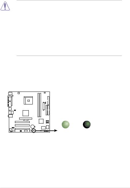
Onboard LED
The motherboard comes with a standby power LED that lights up to indicate that the system is ON, in sleep mode, or in soft-off mode. This is a reminder that you should shut down the system and unplug the power cable before removing or plugging in any motherboard component.
|
SB_PWR |
|
K8V-MX |
|
|
|
ON |
OFF |
K8V-MX Onboard LED |
Standby |
Powered |
Power |
Off |
|
ASUS K8V-MX Motherboard |
1-5 |

1.5 Motherboard Overview
1.5.1 Motherboard layout
PS/2 |
|
|
|
|
|
|
|
|
|
T: Mouse |
|
|
ATX12V |
|
|
|
CPU_FAN |
FLOPPY |
|
B: Keyboard |
|
|
|
|
|
|
|||
COM1 |
|
KBPWR |
|
|
|
|
|
|
|
|
|
|
|
|
|
|
|
||
|
PARALLEL PORT |
|
|
Socket 754 |
184-pin module) |
184-pin module) |
|
CHA FAN |
|
VGA |
|
|
|
|
DIMM1 (64 bit, |
DIMM2 (64 bit, |
ATXPWR |
|
|
USB1 |
|
|
|
|
|
|
|||
USB2 |
|
|
|
|
|
|
|||
|
|
|
USBPW12 |
|
|
|
|||
|
|
|
|
DDR |
DDR |
|
|
|
|
|
|
|
USBPW34 |
|
|
|
|
||
Bottom: |
Top: |
|
|
VIA |
|
|
|
||
USB3 |
RJ-45 |
|
|
|
|
|
|
|
|
USB4 |
|
|
|
|
|
|
|
||
|
|
|
|
K8M800 |
|
|
|
|
|
Top:Line In |
|
|
|
|
|
|
PRI IDE |
SEC IDE |
|
Center:Line Out |
|
|
|
|
|
|
|||
Below:Mic In |
|
|
|
|
|
|
|||
|
|
|
|
|
|
|
|
||
|
|
|
|
AGP |
|
|
|
|
|
|
|
|
|
|
R |
|
|
SATA2 |
|
|
|
|
|
|
|
VIA |
|
||
|
|
|
|
|
|
|
|
|
|
|
|
|
|
PCI1 |
|
VT8237R |
|
|
|
|
|
|
|
K8V-MX |
|
|
|
SATA1 |
|
|
|
|
|
|
|
|
|
|
|
|
|
|
|
PCI2 |
CR2032 3V |
|
|
|
|
|
FP_AUDIO |
|
|
Lithium Cell |
|
Super |
4Mbit |
||
|
|
|
|
|
CMOS Power |
|
BIOS |
||
AD1888 |
AUX |
|
PCI3 |
|
|
I/O |
|
|
|
|
|
|
|
|
|
||||
|
|
|
|
|
|
PANEL |
|||
SPDIF |
|
USBPW56 |
|
SB_PWR |
|
|
|||
|
|
|
|
|
|
||||
|
|
CD |
USBPW78 |
USB78 |
USB56 |
CLRTC |
|
|
|
|
|
|
|
|
|
||||
|
|
|
|
|
|
|
|||
1-6 |
Chapter 1: Product Introduction |
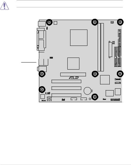
1.5.2 Placement direction
When installing the motherboard, make sure that you place it into the chassis in the correct orientation. The edge with external ports goes to the rear part of the chassis as indicated in the image below.
1.5.3 Screw holes
Place eight (8) screws into the holes indicated by circles to secure the motherboard to the chassis.
Do not overtighten the screws! Doing so may damage the motherboard.
Place this side 

 towards

 the rear of the
chassis
K8V-MX
ASUS K8V-MX Motherboard |
1-7 |
1.6 Central Processing Unit (CPU)
1.6.1 Overview
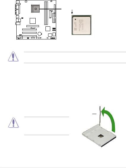
The AMD Athlon™ 64 processor has a gold triangle in one corner. This mark indicates the processor PinA1 that should match a specific corner of the CPU socket.
 Gold Arrow
K8V-MX
K8V-MX CPU Socket 754
Incorrect installation of the CPU into the socket may bend the pins and severely damage the CPU!
1.6.2 Installing the CPU
Follow these steps to install a CPU.
1.Locate the 754-pin ZIF socket on the motherboard.
2.Unlock the socket by pressing the lever sideways, then lift it up to a 90° -100° angle.
Socket
Make sure that the socket lever is lifted up to 90°-100° angle, otherwise the CPU does not fit in completely.
1-8 |
Chapter 1: Product Introduction |
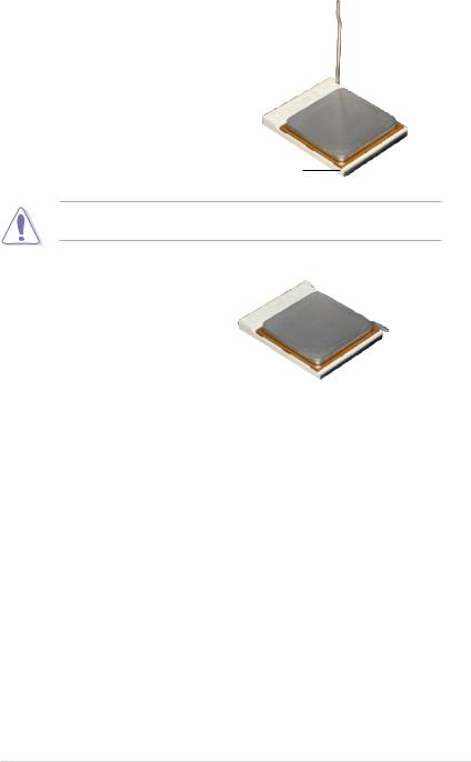
3.Position the CPU above the socket such that the CPU corner with the gold triangle matches the socket corner with a small triangle.
4.Carefully insert the CPU into the socket until it fits in place.
Gold triangle
The CPU fits only in one correct orientation. DO NOT force the CPU into the socket to prevent bending the pins and damaging the CPU!
5.When the CPU is in place, push down the socket lever to secure the CPU. The lever clicks on the side tab to indicate that it is locked.
6.Install a CPU heatsink and fan following the instructions that came with the heatsink package.
7.Connect the CPU fan cable to the CPU_FAN connector on the motherboard.
ASUS K8V-MX Motherboard |
1-9 |
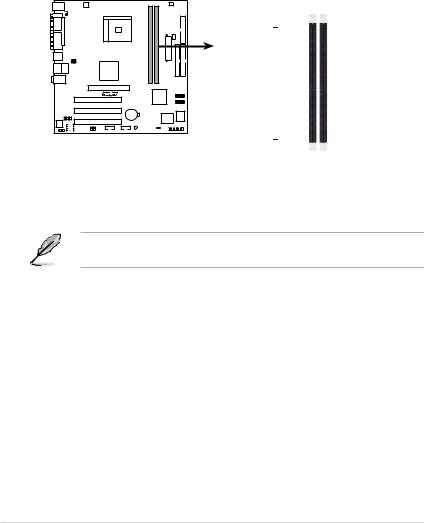
1.7 System memory
1.7.1 Overview
The motherboard comes with two Double Data Rate (DDR) Dual Inline Memory Module (DIMM) sockets. These sockets support up to 2GB system memory using 184-pin PC3200/PC2700/PC2100 unbuffered DDR DIMMs and allow up to 3.2 GB/s data transfer rate.
The following figure illustrates the location of the DDR DIMM sockets.
K8V-MX |
K8V-MX 184-Pin DDR DIMM sockets
DIMM1 |
DIMM2 |
 80 Pins 104 Pins
1.7.2 Memory configurations
You may install 64 MB, 128 MB, 256 MB, 512 MB and 1 GB DDR DIMMs into the DIMM sockets.
For optimum compatibility, it is recommended that you obtain memory modules from qualified vendors. See the Qualified Vendors List (QVL) next page.
1-10 |
Chapter 1: Product Introduction |
Qualified DDR400 DIMMs
The following table lists the PC3200 (DDR400) memory modules that have been tested and qualified for use with this motherboard.
Obtain DDR DIMMs only from qualified vendors for better system performance.
DDR400 Qualified Vendor List (QVL)
Size |
Vendor |
Model |
Brand |
Side(s) |
DIMM support |
A* |
B* |
|
|
Component |
|
||||||||
256MB |
KINGSTON |
KVR400X64C3A/256 |
Hynix |
SS |
HY5DU56822BT-D43 |
• |
|
|
|
512MB |
KINGSTON |
KVR400X64C3A/512 |
Hynix |
DS |
HY5DU56822BT-D43 |
• |
• |
|
|
256MB |
KINGSTON |
KVR400X64C3A/256 |
PSC |
SS |
A2S56D30BTP |
• |
• |
|
|
512MB |
KINGSTON |
KVR400X64C3A/512 |
Hynix |
SS |
HY5DU12822BT-D43 |
• |
• |
|
|
256MB |
KINGSTON |
KVR400X64C3A/256 |
KINGSTON |
SS |
D3208DL3T-5A |
• |
|
|
|
512MB |
KINGSTON |
KVR400X64C3A/512 |
KINGSTON |
DS |
D3208DH1T-5 |
• |
• |
|
|
256MB |
KINGSTON |
KVR333X64C25/256 |
KINGSTON |
SS |
D3208DH1T-6 |
• |
|
|
|
512MB |
KINGSTON |
KVR333X64C25/512 |
KINGSTON |
DS |
D3208DH1T-6 |
• |
|
|
|
256MB |
KINGSTON |
KVR333X64C25/256 |
Hynix |
DS |
HY5DU56822BT-D43 |
• |
• |
|
|
1GB |
KINGSTON |
KVR400X64C3A/1G |
Infineon |
DS |
HYB25D512800BE-5B |
• |
• |
|
|
256MB |
Infineon |
HYS64D32300GU-5-C |
Infineon |
SS |
HYB25D256800CE-5C |
• |
• |
|
|
512MB |
Infineon |
HYS64D64320GU-5-C |
Infineon |
DS |
HYB25D256800CE-5C |
• |
• |
|
|
512MB |
Infineon |
HYS64D64300GU-5-B |
Infineon |
SS |
HYB25D512800CE-5B |
• |
|
|
|
256MB |
Infineon |
HYS64D32300GU-5-C |
Infineon |
SS |
HYB25D256800CE-5C |
• |
• |
|
|
512MB |
Infineon |
HYS64D64320GU-5-C |
Infineon |
DS |
HYB25D256800CE-6C |
• |
• |
|
|
256MB |
HY |
HYMD232646D8J-D43 |
Hynix |
SS |
HY5DU56822DT-D43 |
• |
• |
|
|
512MB |
HY |
HYMD264646D8J-D43 |
Hynix |
DS |
HY5DU56822DT-D43 |
• |
• |
|
|
256MB |
HY |
HYMD232646D8J-J |
Hynix |
SS |
HY5DU56822BT-J |
• |
• |
|
|
512MB |
HY |
HYMD264646D8J-J |
Hynix |
DS |
HY5DU56822BT-J |
• |
• |
|
|
256MB |
CORSAIR |
VS256MB400 |
Value select |
SS |
VS32M8-5 2B0409 |
• |
• |
|
|
256MB |
CORSAIR |
XMS3202v3.1 |
Infineon |
SS |
HYB25D256807BT-5B |
• |
• |
|
|
512MB |
CORSAIR |
XMS3205v1.2 |
Winbond |
DS |
W942508CH-5 |
• |
|
|
|
512MB |
CORSAIR |
VS512MB400 |
Value select |
DS |
VS32M8-5 2B0402 |
• |
• |
|
|
256MB |
CORSAIR |
XMS2700v1.1 |
Winbond |
SS |
W942508BH-6 |
• |
• |
|
|
256MB |
CORSAIR |
VS256MB333 |
SAMSUNG |
SS |
K4H5608380-TCB3 |
• |
• |
|
|
512MB |
CORSAIR |
XMS2702v3.1 |
Mosel |
DS |
V58C2256804SAT6 |
• |
• |
|
|
512MB |
CORSAIR |
XMS3205v1.2 |
Winbond |
DS |
W942508CH-6 |
• |
• |
|
|
512MB |
MICRON |
MT16VDDT6464AG-335GB |
MICRON |
DS |
MT46V32M8TG-6TG |
• |
• |
|
|
256MB |
MICRON |
MT8VDDT3264AG-335GB |
MICRON |
SS |
MT46V32M8TG-6TG |
• |
• |
|
|
256MB |
MICRON |
MT8VDDT3264AG-40BGB |
MICRON |
SS |
MT46V32M8TG-5BG |
• |
• |
|
|
512MB |
MICRON |
MT16VDDT6464AG-40BCB |
MICRON |
DS |
MT46V32M8TG-5BC |
• |
• |
|
|
256MB |
SAMSUNG |
M368L3223FTN-CCC |
SAMSUNG |
SS |
K4H560838F-TCCC |
• |
• |
|
|
512MB |
SAMSUNG |
M368L6423FTN-CCC |
SAMSUNG |
DS |
K4H560838F-TCCC |
• |
• |
|
|
256MB |
SAMSUNG |
M368L3223FTN-CB3 |
SAMSUNG |
SS |
K4H560838F-TCB3 |
• |
|
|
|
512MB |
SAMSUNG |
M368L6423FTN-CB3 |
SAMSUNG |
DS |
K4H560838F-TCB3 |
• |
• |
|
|
256MB |
Winbond |
U24256ADWBG6H20 |
Winbond |
SS |
W942508CH-5 |
• |
• |
|
|
256MB |
Winbond |
U24256AAWBG6H20 |
Winbond |
SS |
W942508CH-6 |
• |
• |
|
|
512MB |
Winbond |
DDR333-512 |
Winbond |
DS |
W942508BH-6 |
• |
• |
|
|
512MB |
Winbond |
U24512ADWBG6H20 |
Winbond |
DS |
W942508CH-5 |
• |
• |
|
|
256MB |
Elpida |
U24256ADEPG6H20 |
Elpida |
SS |
DD2508AKTA-5C |
• |
|
|
|
512MB |
Elpida |
U24512ADEPG6H20 |
Elpida |
DS |
DD2508AMTA |
• |
• |
|
|
256MB |
Transcend |
DDR400-256 |
SAMSUNG |
SS |
K4H560838F-TCCC |
• |
• |
|
|
256MB |
Transcend |
DDR400-256 |
Mosel |
SS |
V58C2256804SAT5B |
• |
• |
|
|
256MB |
Transcend |
103004-0720 |
PSC |
SS |
A2S56D3OBTP |
• |
• |
|
|
512MB |
Transcend |
102709-0001 |
PSC |
DS |
A2S56D3OATP |
• |
• |
|
|
512MB |
Transcend |
DDR400-512 |
Mosel |
DS |
V58C2256804SAT5B |
• |
|
|
|
512MB |
Transcend |
DDR400-512 |
SAMSUNG |
DS |
K4H560838F-TCCC |
• |
• |
|
|
256MB |
Transcend |
111448-0214 |
PSC |
SS |
A2S56D3OBTP |
• |
• |
|
|
512MB |
Transcend |
DDR333-512 |
Hynix |
DS |
HY5DU56822CT-J |
• |
|
|
|
256MB |
Pmi |
3208GATA07-04A7 |
Pmi |
SS |
PM4D328D50406EU |
• |
• |
|
|
512MB |
Pmi |
3208GATA01-04A4 |
Pmi |
DS |
PM4D328S50403DU |
• |
|
|
|
256MB |
KINGMAX |
MPMB62D-38LT3R |
Mosel |
SS |
V58C2256804SAT6 |
• |
• |
|
|
512MB |
KINGMAX |
MPMC22D-38HT3R |
Hynix |
DS |
HY5DU56822BT-J |
• |
• |
|
|
256MB |
KINGMAX |
MPXB62D-38KT3R |
KINGMAX |
SS |
KDL388P4LA-50 |
• |
• |
|
|
(Continued on the next page) |
|
|
|
|
|
|
|
||
|
|
|
|
|
|
|
|
||
ASUS K8V-MX Motherboard |
|
|
|
|
1-11 |
||||

DDR400 Qualified Vendors List
Size |
Vendor |
Model |
Brand |
Side(s) |
DIMM support |
A* |
B* |
Component |
|||||||
256MB |
Mosel |
V826632K24SATG-D3 |
Mosel |
SS |
V58C2256804SAT5 |
• |
• |
512MB |
Mosel |
V826664K24SATG-D3 |
Mosel |
DS |
V58C2256804SAT5 |
• |
|
256MB |
NANYA |
NT256D64S88B1G-5T |
NANYA |
SS |
NT5DS32M8BT-5T |
• |
• |
512MB |
NANYA |
NT512D64S8HB1G-5T |
NANYA |
DS |
NT5DS32M8BT-5T |
• |
• |
256MB |
Apacer |
77.10636.46G |
SAMSUNG |
SS |
K4H560838E-TCCC |
• |
• |
512MB |
Apacer |
77.90728.U1G |
Apacer |
DS |
AM3A568AJT-6B |
• |
• |
256MB |
Apacer |
77.10636.56G |
Mosel |
SS |
V58C2256804Sat5B |
• |
• |
512MB |
Apacer |
77.10736.11G |
Infineon |
DS |
HYB25D256800BT-5B |
• |
|
256MB |
Smart |
U24256ADSRG6H20 |
Smart |
SS |
D32M8XS50H3X4AMV |
• |
|
256MB |
Smart |
U24256ADSRG6H20 |
Smart |
SS |
D32M8XS60HBX4AMV |
• |
• |
512MB |
Smart |
U24512ADSRG6H20 |
Smart |
DS |
D32M8XS50H3X4AMV |
• |
|
512MB |
Smart |
U24512ADSRG6H20 |
Smart |
DS |
D32M8XS60HBX4AMV |
• |
• |
256MB |
TwinMOS |
DDR333-256 |
TwinMOS |
SS |
TMD7608F8E60B |
• |
• |
256MB |
TwinMOS |
M2G9I08A-TT |
TwinMOS |
SS |
TMD7608F8E501 |
• |
• |
512MB |
TwinMOS |
M2G9J16A-TT |
TwinMOS |
DS |
TMD7608F8E501 |
• |
|
256MB |
Promos |
V826632K24SCTG-D0 |
Promos |
SS |
V58C2256804SCT5B |
• |
• |
512MB |
Promos |
V826664K24SCTG-D0 |
Promos |
DS |
V58C2256804SCT5B |
• |
• |
512MB |
BiaoXing |
BXXC22D-38KT3B |
BiaoXing |
DS |
VM256D328BT-5 |
• |
• |
256MB |
Vdata |
MDYVD6F4G2880B1E0H |
Vdata |
SS |
VDD9616A8A-5C |
• |
• |
|
|
|
|
|
|
|
|
Legend:
A - supports one module inserted into either slot, in a Single-channel memory configuration.
B - supports on pair of modules inserted into either the blue slots or the black slots as one pair of Dual-channel memory configuration.
SS - Single-sided
DS - Double-sided
1-12 |
Chapter 1: Product Introduction |
 Loading...