


CUV4X-VM

®
CUV4X-VM
Apollo PM133 Chipset
Socket 370 Motherboard
USER’S MANUAL

ASUS CUV4X-VM User’s Manual
2
USER'S NOTICE
Product Name: ASUS CUV4X-VM
Manual Revision: 1.02 E768
Release Date: April 2001
No part of this manual, including the products and software described in it, may be reproduced,
transmitted, transcribed, stored in a retrieval system, or translated into any language in any form
or by any means, except documentation kept by the purchaser for backup purposes, without the
express written permission of ASUSTeK COMPUTER INC. (“ASUS”).
ASUS PROVIDES THIS MANUAL “AS IS” WITHOUT WARRANTY OF ANY KIND, EI-
THER EXPRESS OR IMPLIED, INCLUDING BUT NOT LIMITED T O THE IMPLIED WAR-
RANTIES OR CONDITIONS OF MERCHANTABILITY OR FITNESS FOR A P ARTICULAR
PURPOSE. IN NO EVENT SHALL ASUS, ITS DIRECTORS, OFFICERS, EMPLOYEES OR
AGENTS BE LIABLE FOR ANY INDIRECT, SPECIAL, INCIDENTAL, OR CONSEQUEN-
TIAL DAMAGES (INCLUDING DAMAGES FOR LOSS OF PROFITS, LOSS OF BUSINESS,
LOSS OF USE OR DA TA, INTERRUPTION OF BUSINESS AND THE LIKE), EVEN IF ASUS
HAS BEEN ADVISED OF THE POSSIBILITY OF SUCH DAMAGES ARISING FROM ANY
DEFECT OR ERROR IN THIS MANUAL OR PRODUCT.
Product warranty or service will not be extended if: (1) the product is repaired, modified or al-
tered, unless such repair, modification of alteration is authorized in writing by ASUS; or (2) the
serial number of the product is defaced or missing.
Products and corporate names appearing in this manual may or may not be registered trademarks
or copyrights of their respective companies, and are used only for identification or explanation
and to the owners’ benefit, without intent to infringe.
• Intel and Pentium are registered trademarks of Intel Corporation.
• VIA is a trademark of VIA Technologies, Inc.
• Windows and MS-DOS are registered trademarks of Microsoft Corporation.
• Adobe and Acrobat are registered trademarks of Adobe Systems Incorporated.
• Trend and ChipAwayVirus are trademarks of Trend Micro Incorporated.
The product name and revision number are both printed on the product itself. Manual revisions
are released for each product design represented by the digit before and after the period of the
manual revision number. Manual updates are represented by the third digit in the manual revision
number.
For previous or updated manuals, BIOS, drivers, or product release information, contact ASUS at
http://www .asus.com.tw or through any of the means indicated on the following page.
SPECIFICA TIONS AND INFORMA TION CONTAINED IN THIS MANUAL ARE FURNISHED
FOR INFORMA TIONAL USE ONL Y, AND ARE SUBJECT TO CHANGE AT ANY TIME WITH-
OUT NOTICE, AND SHOULD NOT BE CONSTRUED AS A COMMITMENT BY ASUS. ASUS
ASSUMES NO RESPONSIBILITY OR LIABILITY FOR ANY ERRORS OR INACCURA-
CIES THAT MAY APPEAR IN THIS MANUAL, INCLUDING THE PRODUCTS AND SOFT-
WARE DESCRIBED IN IT.
Copyright © 2001 ASUSTeK COMPUTER INC. All Rights Reserved.

ASUS CUV4X-VM User’s Manual 3
ASUS CONTACT INFORMATION
ASUSTeK COMPUTER INC. (Asia-Pacific)
Marketing
Address: 150 Li-Te Road, Peitou, Taipei, Taiwan 112
Telephone: +886-2-2894-3447
Fax: +886-2-2894-3449
Email: info@asus.com.tw
Technical Support
MB/Others (Tel): +886-2-2890-7121 (English)
Notebook (Tel): +886-2-2890-7122 (English)
Desktop/Server (Tel):+886-2-2890-7123 (English)
Fax: +886-2-2893-7775
Email: tsd@asus.com.tw
WWW: www.asus.com.tw
FTP: ftp.asus.com.tw/pub/ASUS
ASUS COMPUTER INTERNATIONAL (America)
Marketing
Address: 6737 Mowry Avenue, Mowry Business Center, Building 2
Newark, CA 94560, USA
Fax: +1-510-608-4555
Email: tmd1@asus.com
Technical Support
Fax: +1-510-608-4555
Email: tsd@asus.com
WWW: www.asus.com
FTP: ftp.asus.com/Pub/ASUS
ASUS COMPUTER GmbH (Europe)
Marketing
Address: Harkortstr. 25, 40880 Ratingen, BRD, Germany
Fax: +49-2102-442066
Email: sales@asuscom.de (for marketing requests only)
Technical Support
Hotline: MB/Others: +49-2102-9599-0 Notebook: +49-2102-9599-10
Fax: +49-2102-9599-11
Support (Email): www.asuscom.de/de/support (for online support)
WWW: www.asuscom.de
FTP: ftp.asuscom.de/pub/ASUSCOM

ASUS CUV4X-VM User’s Manual
4
CONTENTS
1. INTRODUCTION ............................................................................. 7
1.1 How This Manual Is Organized ................................................... 7
1.2 Item Checklist .............................................................................. 7
2. FEATURES ........................................................................................ 8
2.1 ASUS CUV4X-VM Motherboard ............................................... 8
2.1.1 Specifications ..................................................................... 8
2.1.2 Performance...................................................................... 10
2.1.3 Intelligence ....................................................................... 11
2.2 Motherboard Components.......................................................... 12
2.2.1 Component Locations....................................................... 13
3. HARDWARE SETUP ...................................................................... 14
3.1 Motherboard Layout .................................................................. 14
3.2 Layout Contents ......................................................................... 15
3.3 Hardware Setup Procedure......................................................... 16
3.4 Motherboard Settings ................................................................. 16
3.5 System Memory ......................................................................... 19
3.5.1 General DIMM Notes....................................................... 19
3.5.2 Memory Installation ......................................................... 20
3.6 Central Processing Unit (CPU) .................................................. 21
3.6.1 CPU Installation ............................................................... 22
3.7 Expansion Cards ........................................................................ 23
3.7.1 Installing an Expansion Card ........................................... 23
3.7.2 Assigning IRQs for Expansion Cards .............................. 24
3.7.3 Accelerated Graphics Port (AGP) .................................... 25
3.8 Connectors ................................................................................ 27
3.8.1 External Connectors ......................................................... 27
3.8.2 Internal Connectors .......................................................... 30
3.9 Starting Up the First Time.......................................................... 38
4. BIOS SETUP..................................................................................... 39
4.1 Managing and Updating Your BIOS .......................................... 39
4.1.1 Upon First Use of the Computer System.......................... 39
4.1.2 Updating BIOS Procedures .............................................. 41
4.2 BIOS Setup Program.................................................................. 43
4.2.1 BIOS Menu Bar................................................................ 44
4.2.2 Legend Bar ....................................................................... 44

ASUS CUV4X-VM User’s Manual 5
CONTENTS
4.3 Main Menu................................................................................. 46
4.3.1 Primary & Secondary Master/Slave ................................. 47
4.3.2 Keyboard Features............................................................ 50
4.4 Advanced Menu ......................................................................... 52
4.4.1 Chip Configuration........................................................... 54
4.4.2 I/O Device Configuration ................................................. 57
4.4.3 PCI Configuration ............................................................ 60
4.4.4 Shadow Configuration...................................................... 61
4.5 Power Menu ............................................................................... 62
4.5.1 Power Up Control............................................................. 64
4.5.2 Hardware Monitor ............................................................ 65
4.6 Boot Menu ................................................................................. 66
4.7 Exit Menu................................................................................... 68
5. SOFTWARE SETUP....................................................................... 71
5.1 Operating Systems ..................................................................... 71
5.1.1 Windows 98 First Time Installation ................................. 71
5.2 CUV4X-VM Motherboard Support CD .................................... 71
5.2.1 Installation Menus ............................................................ 71
5.2.2 Applications...................................................................... 71
6. SOFTWARE REFERENCE ........................................................... 73
6.1 ASUS PC Probe ......................................................................... 73
6.1.1 Starting ASUS PC Probe .................................................. 73
6.1.2 Using ASUS PC Probe ..................................................... 74
6.1.3 ASUS PC Probe Task Bar Icon ........................................ 77
7. APPENDIX........................................................................................ 79
7.1 Glossary ..................................................................................... 79
INDEX ................................................................................................... 83

ASUS CUV4X-VM User’s Manual
6
FCC & DOC COMPLIANCE
Federal Communications Commission Statement
This device complies with FCC Rules Part 15. Operation is subject to the following
two conditions:
• This device may not cause harmful interference, and
• This device must accept any interference received, including interference that
may cause undesired operation.
This equipment has been tested and found to comply with the limits for a Class B
digital device, pursuant to Part 15 of the FCC Rules. These limits are designed to
provide reasonable protection against harmful interference in a residential installation.
This equipment generates, uses and can radiate radio frequency energy and, if not
installed and used in accordance with manufacturer's instructions, may cause harmful
interference to radio communications. However, there is no guarantee that interference
will not occur in a particular installation. If this equipment does cause harmful
interference to radio or television reception, which can be determined by turning the
equipment off and on, the user is encouraged to try to correct the interference by one
or more of the following measures:
• Re-orient or relocate the receiving antenna.
• Increase the separation between the equipment and receiver.
• Connect the equipment to an outlet on a circuit different from that to which the
receiver is connected.
• Consult the dealer or an experienced radio/TV technician for help.
WARNING! Any changes or modifications to this product not expressly approved
by the manufacturer could void any assurances of safety or performance and
could result in violation of Part 15 of the FCC Rules.
Reprinted from the Code of Federal Regulations #47, part 15.193, 1993. Washington DC: Office of the
Federal Register, National Archives and Records Administration, U.S. Government Printing Office.
Canadian Department of Communications Statement
This digital apparatus does not exceed the Class B limits for radio noise emissions
from digital apparatus set out in the Radio Interference Regulations of the Canadian
Department of Communications.
This Class B digital apparatus complies with Canadian ICES-003.
Cet appareil numérique de la classe B est conforme à la norme NMB-003 du Canada.
ASUS CUV4X-VM User’s Manual 7
1.1 How This Manual Is Organized
This manual is divided into the following sections:
1. INTRODUCTION Manual information and checklist
2. FEATURES Production information and specifications
3. HARDWARE SETUP Instructions on setting up the motherboard.
4. BIOS SETUP Instructions on setting up the BIOS
5. SOFTWARE SETUP Instructions on setting up the included software
6. SOFTWARE REFERENCE Reference material for the included software
7. APPENDIX Optional items and general reference
1.2 Item Checklist
Check that your package is complete. If you discover damaged or missing items,
contact your retailer.
1. INTRODUCTION
1. INTRODUCTION
Manual / Checklist
Package Contents
(1) ASUS Motherboard
(1) 40-pin 80-conductor ribbon
cable for internal UltraDMA/
100/66 or UltraDMA/33 IDE
drives
(1) Ribbon cable for two 3.5”
floppy disk drives
(1) ASUS Support CD with drivers
and utilities
(1) Bag of spare jumper caps
(1) User’s Manual
Optional Items
ASUS Modem MR
ASUS IrDA-compliant infrared
module

8
ASUS CUV4X-VM User’s Manual
2.1 ASUS CUV4X-VM Motherboard
The ASUS CUV4X-VM is an entry-level motherboard powered by Intel
®
Pentium
®
/
Celeron™ processors running at 533MHz to 1GHz. The motherboard is designed
with features and interfaces to offer value while minimizing cost.
2.1.1 Specifications
• Processor:
Intel Pentium
®
III 100/133MHz FSB Coppermine core FC-PGA
Intel Celeron™ 100/66MHz FSB Coppermine core FC-PGA
• North/South Bridge System Chipset: Features the VIA Apollo ProSavage
PM133 chipset composed of VT8605 North Bridge and VT82C686B South
Bridge
• PC133 SDRAM / HSDRAM Support: Equipped with two Dual Inline Memory
Module (DIMM) sockets to support up to 1GB of memory using unbuffered
PC133/100-compliant SDRAMs.
• UltraDMA/100/66/33 Support: Comes with an onboard PCI Bus Master IDE
controller with two connectors that support four IDE devices on two channels.
Supports UltraDMA/100, UltraDMA/66, UltraDMA/33, PIO Modes 3 & 4, Bus
Master IDE DMA Mode 2, and Enhanced IDE devices, such as DVD-ROM,
CD-ROM, CD-R/RW, LS-120, and Tape Backup drives.
• Super Multi-I/O: Builts-in I/O capability through the VT82C686B South Bridge
to support standard components that include a parallel port, two serial ports,
one floppy disk drive, PS/2 keyboard and mouse, a game port, and four USB
ports.
• IrDA: Supports an optional infrared port module for wireless interface.
• Wake-On-LAN: Supports Wake-On-LAN activity through a WOL connector
• Wake-On-Ring: Supports Wake-On-Ring activity through a PCI modem card
that supports a WOR connector.
• PC Health Monitoring: Provides an easy way to test and manage system status
information, such as CPU and system voltages, temperatures, and fan status
through the VT82C686B South Bridge and the bundled ASUS PC Probe.
• PCI Expansion Slots: Provides three 32-bit PCI (Rev . 2.2) expansion slots that
support Bus Master PCI cards, such as SCSI or LAN cards, with 133MB/s
maximum throughput.
• AGP 4X Slot: Supports AGP/2X/4X cards for high performance, component-
level interconnection targeted at 3D graphical applications supporting 133MHz
4X mode.
2. FEATURES
Specifications
2. FEATURES

ASUS CUV4X-VM User’s Manual 9
2. FEATURES
2. FEATURES
Specifications
• Smart BIOS: 2Mb firmware provides Vcore and CPU/SDRAM frequency
adjustments, boot block write protection, and HD/SCSI/MO/ZIP/CD/Floppy boot
selection.
• Enhanced ACPI and Anti-Boot Virus Pr otection: Programmable BIOS (Flash
EEPROM) that offers enhanced ACPI for Windows 98 compatibility, built-in
firmware-based virus protection, and autodetection of most devices for a virtual
automatic setup.
• Desktop Management Interface (DMI): Supports DMI through BIOS that
allows hardware to communicate within a standard protocol and create a higher
level of compatibility. (Requires DMI-enabled components.)
• Onboard Audio: Audio models come with the AC ‘97-compliant interfaces
that support integrated audio and modem features that comprise digital audio
engine with 3D-hardware accelerator, on-chip sample rate converter, and a
professional wavetable.

10
ASUS CUV4X-VM User’s Manual
2. FEATURES
Performance
2. FEATURES
2.1.2 Performance
• ACPI Ready: Advanced Configuration Power Interface (ACPI) provides more
Energy Saving Features for operating systems that support OS Direct Power
Management (OSPM) functionality. With these features employed in the OS,
PCs can be ready around the clock but comply with energy saving standards. To
fully utilize the ACPI benefits, use an ACPI-supported OS such as Windows
98/2000/Millenium.
• PC’99 Compliant: Both the BIOS and hardware levels of ASUS smart series
motherboards are PC’99 compliant. The new PC’99 requirements for systems
and components are based on the following high-level goals: Support for Plug-
n-Play compatibility and power management for configuring and managing all
system components, and 32-bit device drivers and installation procedures for
Windows 95/98/NT. Color-coded connectors and descriptive icons make
identification easy as required by PC’99.
• High-Speed Data Transfer Interface: Support for UltraDMA/100 through the
onboard IDE bus master controller triples the UltraDMA/33 burst transfer rate.
UltraDMA/100 is backward compatible with DMA/66, DMA/33, and other
existing DMA devices to save the need to upgrade current EIDE/IDE drives.
(UltraDMA/100/66 requires a 40-pin 80-conductor cable).
• Concurrent PCI: Concurrent PCI allows multiple PCI transfers from PCI master
busses to the memory and processor.

ASUS CUV4X-VM User’s Manual 11
2. FEATURES
2. FEATURES
Intelligence
2.1.3 Intelligence
• Auto Fan Off: The system fans powers off automatically even in sleep mode.
This function reduces both energy consumption and system noise, and is an
important feature in implementing silent PC systems.
• Dual Function Power Button: Pushing the power button for less than 4 seconds
when the system is in the working state places the system into one of two states:
sleep mode or soft-off mode, depending on the BIOS or OS setting (see PWR
Button < 4 Secs in 4.5 Power Menu). When you press the power button for
more than 4 seconds, the system enters the soft-off mode regardless of the BIOS
setting.
• Fan Status Monitoring and Alarm: To prevent system overheat and system
damage, the CPU and system fans can be monitored for RPM and failure. All
fans are set for its normal RPM range and alarm thresholds.
• Power LED (requir es ACPI OS support): The power LED indicates the system
status.
• Remote Ring-On (requires modem): This feature allows you to turn off the
computer remotely through an internal or external modem. With this benefit on-
hand, users can access vital information from their computers anywhere.
• System Resources Alert: Today’s operating systems such as Windows 98/ME
and Windows NT/2000, require much more memory and hard drive space to
present enormous user interfaces and run large applications. The system resource
monitor warns the user before the system resources are used up to prevent possible
application crashes. Suggestions provide the user some information on managing
their limited resources more efficiently.
• Temperature Monitoring and Alert: CPU temperature is monitored by the
VT82C686B prevent system overheat and system damage.
• Voltage Monitoring and Alert: System voltage levels are monitored to ensure
stable voltage to critical motherboard components. Voltage specifications are
more critical for future processors, so monitoring is necessary to ensure proper
system configuration and management.

12
ASUS CUV4X-VM User’s Manual
2. FEATURES
2. FEATURES
M/B Components
Location
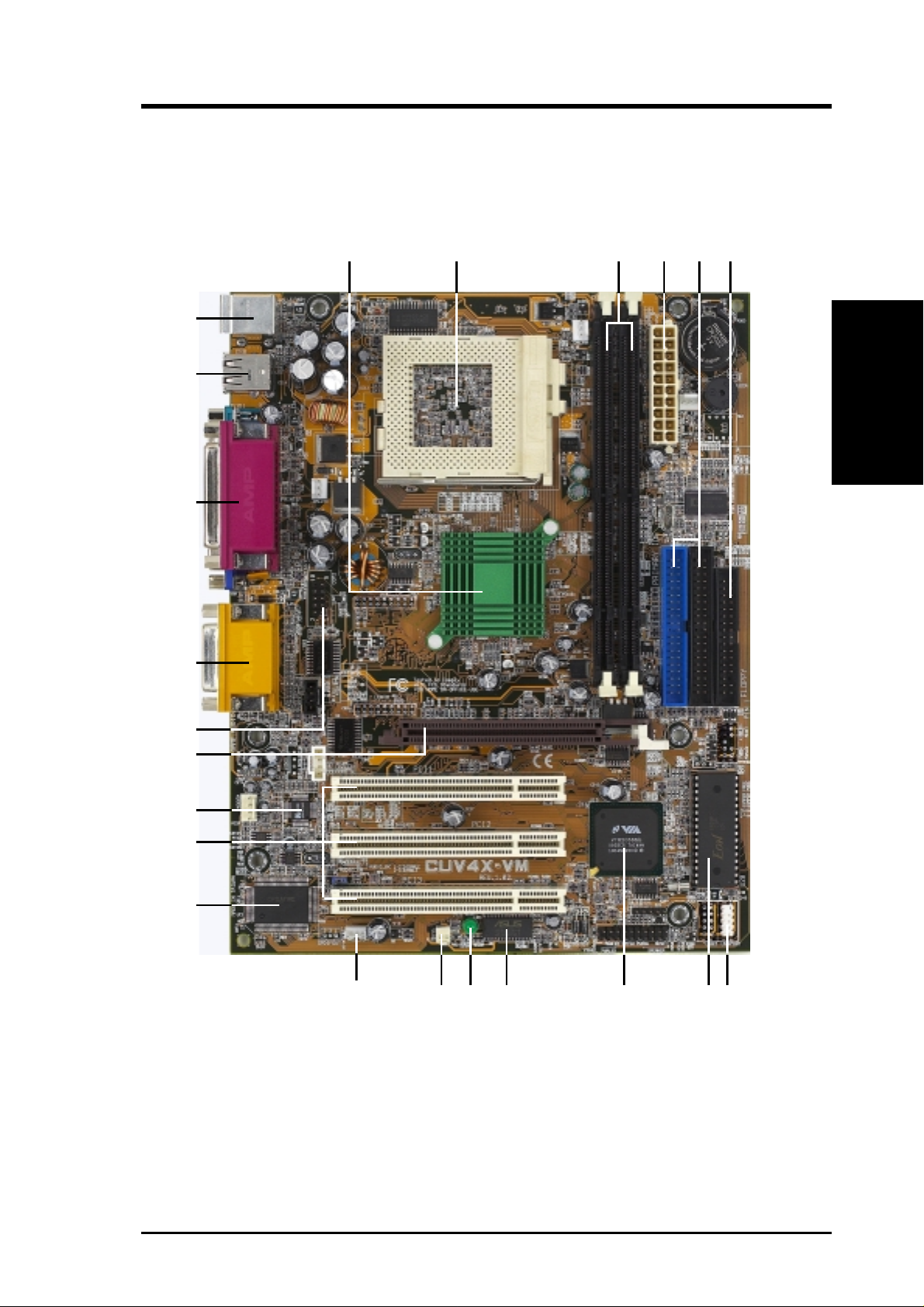
Processor Support Socket 370 for Intel Pentium/Celeron Processors .................... 2
System Chipsets VIA VT8605 North Bridge....................................................... 1
VIA VT82C686B South Bridge ............................................... 9
2Mbit Programmable Flash EEPROM ..................................... 8
Main Memory 2 DIMM Sockets for up to 1GB Memory Support .................. 3
PC133 SDRAM support
Expansion Slots 3 PCI Slots .............................................................................. 15
1 Accelerated Graphics Port (AGP) Slot ................................ 17
System I/O Floppy Disk Drive Connector .................................................. 6
IDE Connectors (UltraDMA/100 Support) .............................. 5
Parallel Port .................................................................. (Top) 20
Serial Port 1 (COM1) ............................................. (Bottom) 20
Serial Port 2 (COM2) ............................................................. 18
Video Port ............................................................... (Bottom) 20
USB Connectors (Port 0 & Port 1) ........................................ 21
USB Connectors (Port 2 & Port 3) .......................................... 7
PS/2 Mouse Connector ................................................. (Top) 22
PS/2 Keyboard Connector ...................................... (Bottom) 22
Wake-Up Features Wake-On-LAN Connector...................................................... 13
Wake-On-Ring Connector ...................................................... 12
Hardware Monitoring System Voltage Monitoring ASUS ASIC ............................... 10
3 Fan Connectors
Audio Features (on audio models only)
Creative CT5880 Audio Controller ........................................ 14
AC ’97 v2.1 Audio Codec ...................................................... 16
Game/MIDI Port........................................................... (Top) 19
Line Out Connector ................................................ (Bottom) 19
Line In Connector................................................... (Bottom) 19
Microphone Connector ........................................... (Bottom) 19
Power ATX Power Connector ............................................................. 4
Onboard Power LED .............................................................. 11
Form Factor Micro A TX
2.2 Motherboard Components
See opposite page for locations.
ASUS CUV4X-VM User’s Manual 13
2. FEATURES
2. FEATURES
M/B Components
2.2.1 Component Locations
4
21
20
17
22
23
8
1
5
7
15
6
18
911
13
12 10
19
14
16

14
ASUS CUV4X-VM User’s Manual
3. HARDWARE SETUP
3.1 Motherboard Layout
Motherboard Layout
3. H/W SETUP
NOTE: The Creative CT5880 audio chipset, audio codec, and the external
and internal audio connectors are optional components, and are present in
audio models only . These components are grayed in the above motherboard
layout.
19.2cm (7.56in)
24.4cm (9.6in)
PCI 2
CUV4X-VM
Socket 370
VIA
VT82C686B
Chipset
PCI 1
DIMM Socket 1 (64/72-bit, 168-pin module)
0
1
DIMM Socket 2 (64/72-bit, 168-pin module)
2
3
Flash EEPROM
(Programable BIOS)
PCI 3
CR2032 3V
Lithium Cell
CMOS Power
VIA
VT8605
Chipset
Primary IDE
Secondary IDE
FLOPPY
R263
AUX
MODEM
CD
IR
Audio
Codec
CREATIVE
CT5880
CHA_FAN
CPU_FAN
GAME_AUDIO
Line
Out
Line
In
Mic
In
COM1
PARALLEL PORT
VGA
PS/2
T: Mouse
B: Keyboard
Bottom:
USB1
USB2
PANEL
WOLCON
WOR
LED
PWR_FAN
ATX Power Connector
COM2
USBPORT
IDELED
ASUS
ASIC
AUDIO_EN
Accelerated Graphics Port (AGP)

ASUS CUV4X-VM User’s Manual 15
3. HARDWARE SETUP
3.2 Layout Contents
Motherboard Settings
1) AUDIO_EN p. 17 Enable/DisableOnboard Audio Controller
2) R263 p. 17 Clear RTC RAM
Expansion Slots/Sockets
1) DIMM 1/2 p. 19 System Memory Support
2) Socket 370 p. 21 CPU Support
3) PCI 1/2/3 p. 23 32-bit PCI Bus Expansion Slots
4) AGP p. 25 Accelerated Graphics Port (AGP) Slot
External Connectors
1) PS2KBMS p. 27 PS/2 Mouse Port (6-pin female)
2) PS2KBMS p. 27 PS/2 Keyboard Port (6-pin female)
3) USB p. 27 Universal Serial Bus Ports 1 & 2 (two 4-pin female)
4) PRINTER p. 28 Parallel Port (25-pin female)
5) COM1 p. 28 Serial Ports (9-pin /10-1 pin male)
6) VGA p. 28 Video Port (15-pin female)
7) GAME_AUDIO (Top) p. 29 Game/MIDI Port (15-pin female)
8) GAME_AUDIO (Bottom) p. 29 Audio Ports (1/8” jacks)
Internal Connectors
1) IDELED p. 30 IDE Activity LED (2-pin)
2) FLOPPY p. 30 Floppy Disk Drive Connector (34-pin)
3) PRIMARY IDE p. 31 IDE Connectors (two 40-1 pin)
SECONDARY IDE
4) WOL_CON p. 32 Wake-On-LAN Connector (3-pin)
5) WOR p. 32 Wake-On-Ring Connector (2-pin)
6) CP U/PWR/CHA_FAN p. 31 CPU, Power, and Chassis Fan Connectors (3-pin)
7) IR p. 34 Standard Infrared Module Connector (5-pin)
8) USBPORT p. 34 Universal Serial Bus Header (10-1 pin)
9) CD/AUX/MODEM p. 35 Internal Audio Connectors (4-1 pin)
10) COM2 p. 35 Serial Port 2 Connector (10-1 pin)
11) ATXPWR p. 36 ATX Power Supply Connector (20-pin)
12)
PWR.LED (
PANEL
)
p. 37 System Power LED Lead (3-pin)
13) SPEAKER (PANEL) p. 37 System Warning Speaker Lead (4-pin)
14) SMI (PANEL) p. 37 System Management Interrupt Lead (2-pin)
15) PWR.SW (PANEL) p. 37 ATX / Soft-Off Switch Lead (2-pin)
16) RESET (PANEL) p. 37 Reset Switch Lead (2-pin)
Layout Contents
3. H/W SETUP
16
ASUS CUV4X-VM User’s Manual
3. HARDWARE SETUP
Motherboard Settings
3. H/W SETUP
3.3 Hardware Setup Procedure
Complete the following steps before using your computer:
1. Check motherboard settings
2. Install memory modules
3. Install the Central Processing Unit (CPU)
4. Install Expansion Cards
5. Connect ribbon cables, panel wires, and power supply cables
6. Configure the BIOS parameter settings
3.4 Motherboard Settings
This section tells you how to change motherboard function settings.
WARNING! Computer motherboards and expansion cards contain very delicate
Integrated Circuit (IC) chips. To avoid damaging them due to static electricity,
follow these precautions whenever you work on your computer .
1. Unplug the computer when working on the internal components.
2. Use a grounded wrist strap or touch a safely grounded object or to a metal
object, such as the power supply case, before handling computer components.
3. Hold components by the edges and try not to touch the IC chips on them.
4. Whenever you uninstall any component, place the components on a grounded
antistatic pad or in the bag that came with the components.
5. Before you install or r emove any component, ensure that the A TX power
supply is switched off or the power cord is detached from the power
supply. Failure to do so may cause severe damage to the motherboard,
peripherals, and/or components.
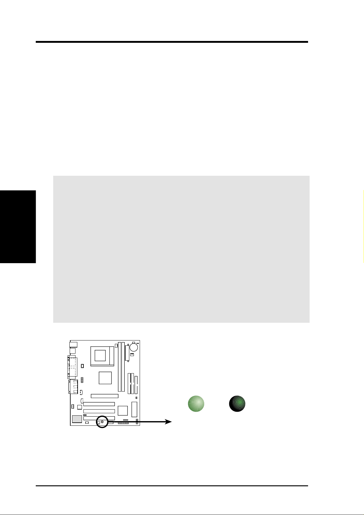
CUV4X-VM Onboard LED
ON OFF
Standby
Power
Powered
Off
LED
CUV4X-VM
ASUS CUV4X-VM User’s Manual 17
3. HARDWARE SETUP
3. H/W SETUP
Motherboard Settings
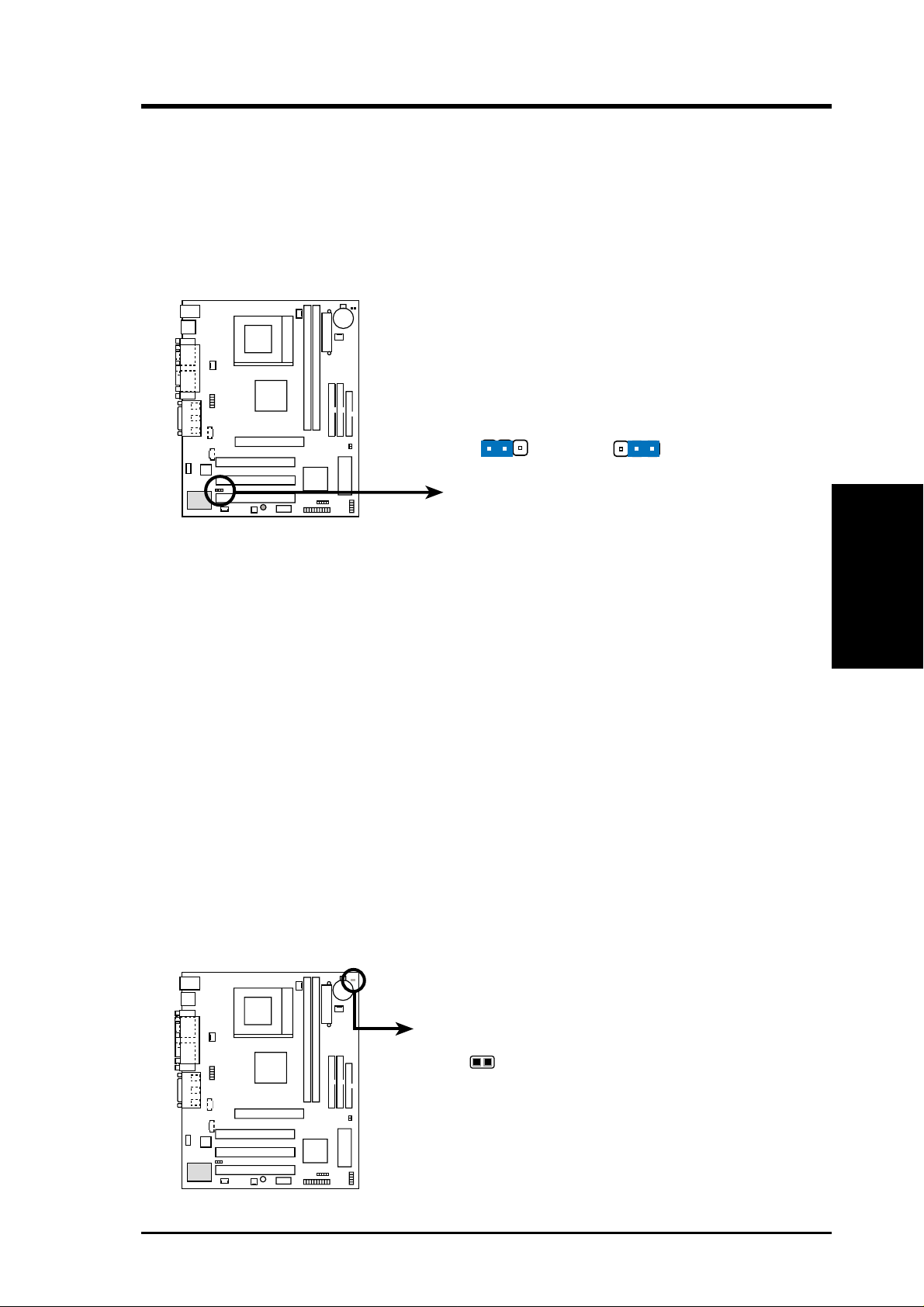
1) Onboard Audio Controller (3-pin AUDIO_EN) (on audio models only)
This jumper allows you to enable or disable the audio CODEC on the
motherboard. Disable the audio CODEC if you desire to install a PCI audio card
on one of the PCI slots. The default setting is ENABLE. (NOTE: If you install a
PCI audio card, disable the parameter Onboard AC97 Controller in 4.4.2 I/O
Device Configuration in BIOS.)
2) Clear RTC RAM (2-pin R263)
These solder points allow you to clear the Real Time Clock (RTC) RAM in
CMOS. You can clear the CMOS memory of date, time, and system setup
parameters by erasing the CMOS RTC RAM data. The RAM data in CMOS,
that include system setup information such as system passwords, is powered by
the onboard button cell battery.
To erase the RTC RAM:
1. Turn OFF the computer and unplug the power cord.
2. Remove the battery.
3. Short the solder points.
4. Re-install the battery.
5. Plug the power cord and turn ON the computer.
6. Hold down the <Del> key during the boot process and enter BIOS setup to
re-enter data.
CUV4X-VM
CUV4X-VM Onboard Audio Setting
Disable
(Default)
Enable
AUDIO_EN
12
2
3
CUV4X-VM Clear RTC RAM
Short solder points
to Clear CMOS
R263
CUV4X-VM

18
ASUS CUV4X-VM User’s Manual
3. HARDWARE SETUP
3. H/W SETUP
Motherboard Settings
(This page was intentionally left blank.)
ASUS CUV4X-VM User’s Manual 19
3. HARDWARE SETUP
System Memory
3. H/W SETUP
3.5 System Memory
This motherboard uses only Dual Inline Memory Modules (DIMMs). Two DIMM
sockets are available for 3.3Volt (power level) unbuffered Synchronous Dynamic
Random Access Memory (SDRAM) of 16, 32, 64, 128, 256, or 512MB densities for
a system memory configuration of 32MB up to 1GB. One side (with memory chips)
of the DIMM takes up one row on the motherboard.
Install memory in any combination as follows:
DIMM Location 168-pin DIMM Total Memory
Socket 1 (Rows 0&1) SDRAM 16, 32, 64, 128, 256, 512MB x1
Socket 2 (Rows 2&3) SDRAM 16, 32, 64, 128, 256, 512MB x1
Total System Memory (Max. 1GB) =
3.5.1 General DIMM Notes
• DIMMs that have more than 18 chips are not supported on this motherboard.
• For the system CPU bus to operate 100MHz/133MHz, use only PC100-/PC133-
compliant DIMMs.
• ASUS motherboards support Serial Presence Detect (SPD) DIMMs. This is the
memory of choice for best performance vs. stability.
• SDRAM chips are generally thinner with higher pin density than EDO (Extended
Data Output) chips.
• BIOS shows SDRAM memory on bootup screen.
• Single-sided DIMMs come in 16, 32, 64,128, 256MB; double-sided come in 32, 64,
128, 256, 512MB.
W ARNING! Make sure that the DIMM you use can handle the specified SDRAM
speeds, otherwise the computer will not boot.
20 ASUS CUV4X-VM User’s Manual
3. HARDWARE SETUP
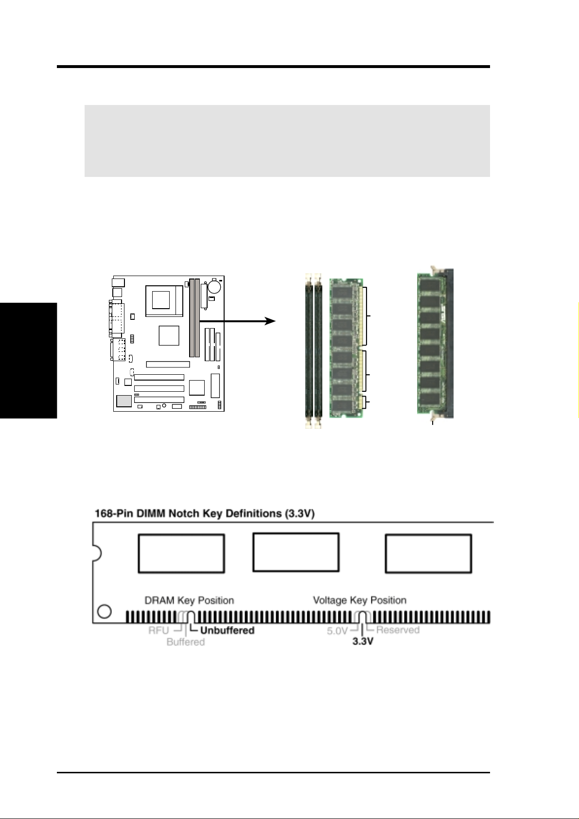
Insert the module(s) into the DIMM sockets as shown. Because the number of pins
are different on either side of the breaks, the module only fits in one direction. SDRAM
DIMMs have different pin contacts on each side and have a higher pin density than
DRAM SIMMs.
The notches on the DIMM shifts between left, center, or right to identify the type
and also to prevent the wrong type from being inserted into the DIMM slot on the
motherboard. You must tell your retailer the correct DIMM type before purchasing.
This motherboard supports four clock signals per DIMM.
The DIMMs must be 3.3Volt unbuffered SDRAMs. To determine the DIMM type,
check the notches on the DIMMs (see the figure below).
WARNING! Make sure that you unplug the power supply when adding or
removing memory modules or other system components. Failure to do so may
cause severe damage to both the motherboard and expansion cards (see 3.3
Hardware Setup Procedure for more information).
System Memory
3. H/W SETUP
3.5.2 Memory Installation
CUV4X-VM 168-Pin DIMM Sockets
Lock
20 Pins
60 Pins
88 Pins
CUV4X-VM
ASUS CUV4X-VM User’s Manual 21
3. HARDWARE SETUP
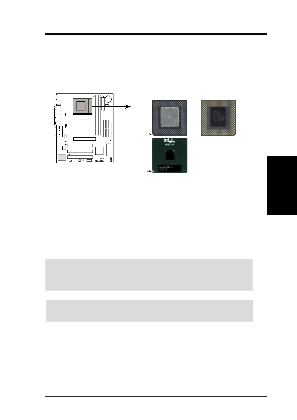
3.6 Central Processing Unit (CPU)
The motherboard comes with a ZIF Socket for the supported CPUs listed in section
2.1.1 Specifications. The following illustration shows the CPU socket location on
the motherboard and the correct CPU orientation.
Note in the illustration that CPUs have marks (usually a notch or a gold mark on one
corner) to help you identify the proper orientation and enable you to correctly install
a CPU. It is important that you match the marked corner of the CPU with the
corresponding corner on the socket so as not to damage the CPU pins.
The CPU picture above is for reference only. Usually, when you buy a CPU, the
heatsink and fan are already attached to the CPU. If a heatsink and fan did not come
with the package, make sure you obtain one before installing the CPU.
Proceed to the next section for the steps on how to properly install a CPU.
CAUTION! Be careful not to scrape the motherboard when mounting/unmounting
a clamp-style processor fan to avoid damaging the motherboard.
WARNING! You must install the proper heatsink and fan to the CPU. Failure to
do so will cause the CPU to overheat and may damage both the CPU and the
motherboard. Install an auxillary fan, if necessary.
CPU
3. H/W SETUP
CUV4X-VM Socket 370
Socket 370 CPU (Top) Socket 370 CPU (Bottom)
Notch
Gold Arrow
Celeron
Pentium III
CUV4X-VM
22 ASUS CUV4X-VM User’s Manual
3. HARDWARE SETUP
CPU Installation
3. H/W SETUP
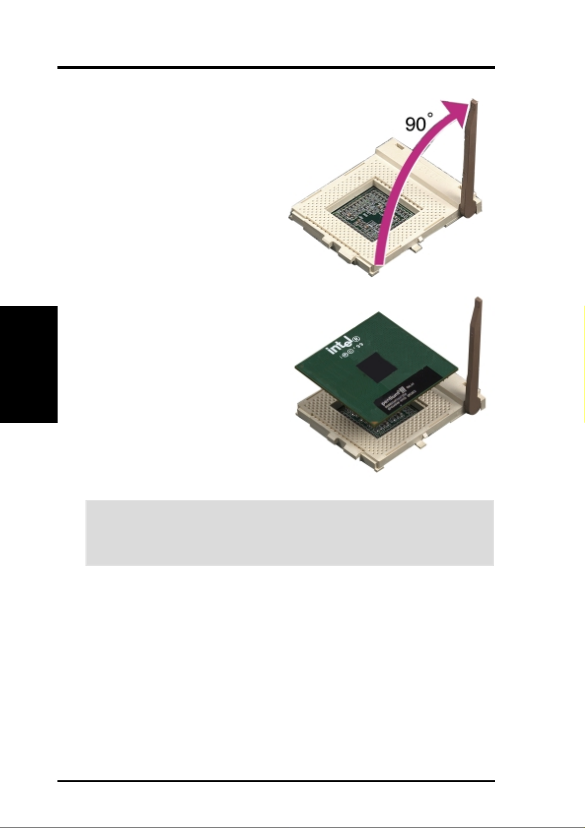
3.6.1 CPU Installation
Follow these steps to install a CPU.
1. Locate the ZIF socket on the
motherboard.
2. Unlock the socket by pressing the
lever sideways then lifting it up to a
90°-100° angle.
5. When the CPU is in place, press it firmly on the socket while you push down the
socket lever to secure the CPU. The lever clicks on the socket indicating that it
is locked.
6. Attach the heatsink and fan to the CPU, if they were not pre-installed by the
vendor . Refer to the installation instructions that came with the heatsink and fan.
CAUTION! The CPU fits only in one orientation. DO NOT force the CPU into
the socket to prevent bending the pins and damaging the CPU. If the CPU does
not fit completely, check its orientation or check for bent pins.
NOTE: Do not forget to set the correct Bus Frequency and Multiple (frequency
multiple setting is available only on unlocked processors) for the processor to avoid
start-up problems.
3. Position the CPU above the socket
such that its notched or marked
corner matches the socket corner
near the end of the lever, while
making sure that the CPU is parallel
to the socket.
4. Carefully insert the CPU into the
socket until it fits in place.
ASUS CUV4X-VM User’s Manual 23
3. HARDWARE SETUP
Expansion Cards
3. H/W SETUP
3.7 Expansion Cards
In the future, you may need to install expansion cards. The motherboard has five
PCI expansion slots to support these cards. Follow the steps in the next section
when installing expansion cards.
WARNING! Unplug the system power cord when adding or removing expansion
cards or other system components. Failure to do so may cause severe damage to
both the motherboard and expansion cards.
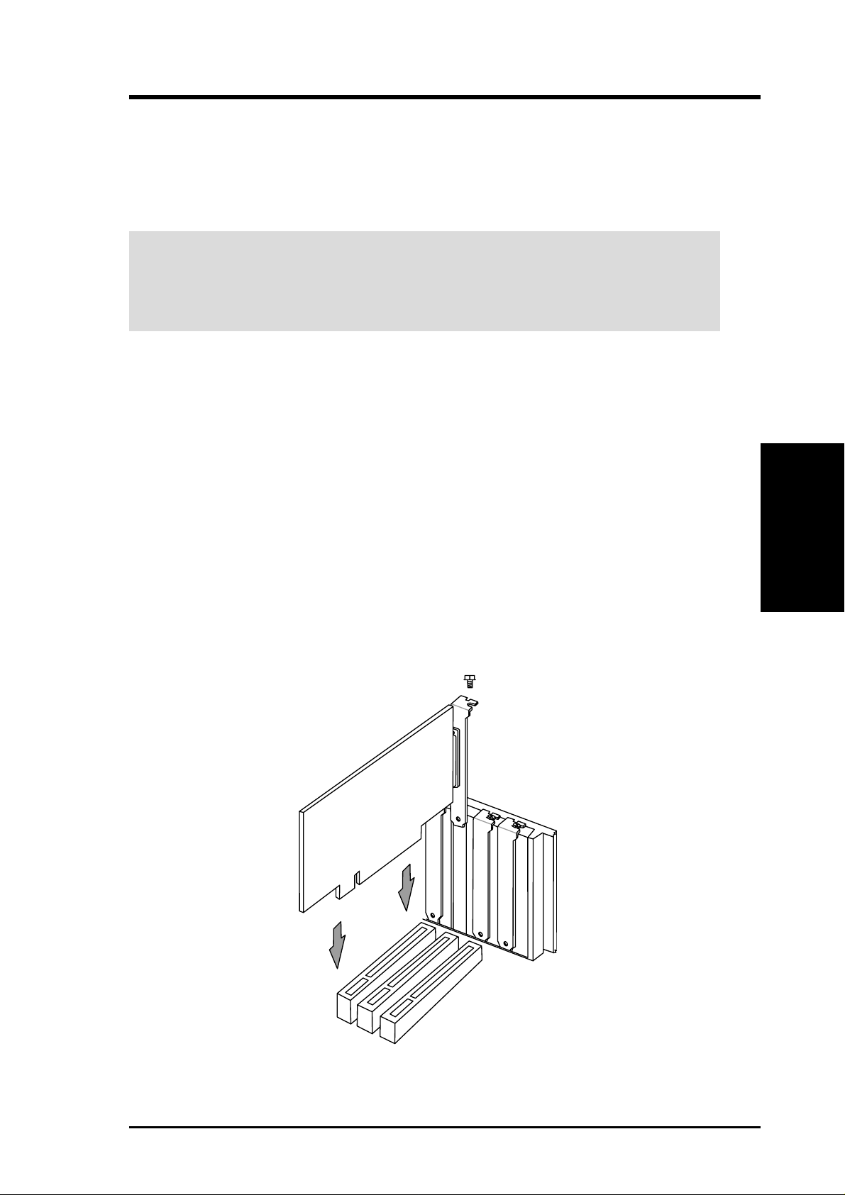
3.7.1 Installing an Expansion Card
1. Read the documentation that comes with the expansion card and make any
necessary hardware settings for the card before installing it.
2. Remove the chassis cover and the bracket plate on the slot you intend to use
(assuming that the motherboard is already installed in a chassis). Keep the screw
for later use.
3. Align the card connectors with the slot and press firmly until the card fits in
place.
4. Secure the card to the slot with the screw you removed earlier.
5. Replace the system cover.
6. Change the necessary BIOS settings, if any.
(see section 4.4.3 PCI Configuration to change the settings.)
7. Install the necessary software drivers for the expansion card.

24 ASUS CUV4X-VM User’s Manual
3. HARDWARE SETUP
Expansion Cards
3. H/W SETUP
3.7.2 Assigning IRQs for Expansion Cards
Some expansion cards need an IRQ to operate. Generally , an IRQ must be exclusively
assigned to one use. In a standard design, there are 16 IRQs available but most of
them are already in use, leaving 6 IRQs free for expansion cards. If your motherboard
has PCI audio onboard, an additional IRQ will be used. If your motherboard also
has MIDI enabled, another IRQ will be used, leaving 4 IRQs free.
IMPORTANT: If using PCI cards on shared slots, make sure that the drivers support
“Share IRQ” or that the cards do not need IRQ assignments. Conflicts arise between
the two PCI groups that will make the system unstable or cards inoperable.
The following table lists the default IRQ assignments for standard PC devices. Use
this table when configuring your system and for resolving IRQ conflicts.
Standard Interrupt Assignments
IRQ Priority Standard Function
0 1 System Timer
1 2 Keyboard Controller
2 N/A Programmable Interrupt
3* 11 Communications Port (COM2)
4* 12 Communications Port (COM1)
5* 13 Sound Card (sometimes LPT2)
6 14 Floppy Disk Controller
7* 15 Printer Port (LPT1)
8 3 System CMOS/Real Time Clock
9* 4 ACPI Mode when used
10* 5 IRQ Holder for PCI Steering
11* 6 IRQ Holder for PCI Steering
12* 7 PS/2 Compatible Mouse Port
13 8 Numeric Data Processor
14* 9 Primary IDE Channel
15* 10 Secondary IDE Channel
*These IRQs are usually available for ISA or PCI devices.
Interrupt Request Table for this Motherboard
INT-A INT-B INT-C INT-D
PCI slot 1 shared —— —
PCI slot 2 — shared ——
PCI slot 3 ——shared —
Onboard audio controller ———shared
Onboard USB controller ———shared
ASUS CUV4X-VM User’s Manual 25
3. HARDWARE SETUP
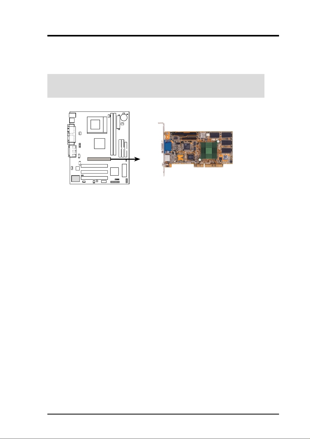
CAUTION! To avoid damaging the AGP/2X/4X graphics card, unplug the system
power cord before installing the card into the slot.
3.7.3 Accelerated Graphics Port (AGP)
This motherboard has an Accelerated Graphics Port (AGP) slot to support AGP/2X/
4X graphics cards, such as an ASUS AGP-V6800DDR/64M.
CUV4X-VM Accelerated Graphics Port (AGP)
CUV4X-VM

26 ASUS CUV4X-VM User’s Manual
3. HARDWARE SETUP
(This page was intentionally left blank.)
 Loading...