


 ® CUSI-FX
Socket 370 FlexATX Motherboard
USER’S MANUAL

USER'S NOTICE
No part of this manual, including the products and software described in it, may be reproduced, transmitted, transcribed, stored in a retrieval system, or translated into any language in any form or by any means, except documentation kept by the purchaser for backup purposes, without the express written permission of ASUSTeK COMPUTER INC. (“ASUS”).
ASUS PROVIDES THIS MANUAL “AS IS” WITHOUT WARRANTY OF ANY KIND, EITHER EXPRESS OR IMPLIED, INCLUDING BUT NOT LIMITED TO THE IMPLIED WARRANTIES OR CONDITIONS OF MERCHANTABILITY OR FITNESS FOR A PARTICULAR PURPOSE. IN NO EVENT SHALL ASUS, ITS DIRECTORS, OFFICERS, EMPLOYEES OR AGENTS BE LIABLE FOR ANY INDIRECT, SPECIAL, INCIDENTAL, OR CONSEQUENTIAL DAMAGES (INCLUDING DAMAGES FOR LOSS OF PROFITS, LOSS OF BUSINESS, LOSS OF USE OR DATA, INTERRUPTION OF BUSINESS AND THE LIKE), EVEN IF ASUS HAS BEEN ADVISED OF THE POSSIBILITY OF SUCH DAMAGES ARISING FROM ANY DEFECT OR ERROR IN THIS MANUAL OR PRODUCT.
Product warranty or service will not be extended if: (1) the product is repaired, modified or altered, unless such repair, modification of alteration is authorized in writing by ASUS; or (2) the serial number of the product is defaced or missing.
Products and corporate names appearing in this manual may or may not be registered trademarks or copyrights of their respective companies, and are used only for identification or explanation and to the owners’ benefit, without intent to infringe.
•SiS is a trademark of Silicon Integrated Corporation.
•Intel, Celeron, LANDesk, and Pentium are trademarks of Intel Corporation.
•IBM and OS/2 are registered trademarks of International Business Machines.
•Symbios is a registered trademark of Symbios Logic Corporation.
•Windows and MS-DOS are registered trademarks of Microsoft Corporation.
•Adobe and Acrobat are registered trademarks of Adobe Systems Incorporated.
The product name and revision number are both printed on the product itself. Manual revisions are released for each product design represented by the digit before and after the period of the manual revision number. Manual updates are represented by the third digit in the manual revision number.
For previous or updated manuals, BIOS, drivers, or product release information, contact ASUS at http://www.asus.com.tw or through any of the means indicated on the following page.
SPECIFICATIONS AND INFORMATION CONTAINED IN THIS MANUAL ARE FURNISHED FOR INFORMATIONAL USE ONLY, AND ARE SUBJECT TO CHANGE AT ANY TIME WITHOUT NOTICE, AND SHOULD NOT BE CONSTRUED AS A COMMITMENT BY ASUS. ASUS ASSUMES NO RESPONSIBILITY OR LIABILITY FOR ANY ERRORS OR INACCURACIES THAT MAYAPPEAR IN THIS MANUAL, INCLUDING THE PRODUCTS AND SOFTWARE DESCRIBED IN IT.
Copyright © 2001 ASUSTeK COMPUTER INC. All Rights Reserved.
Product Name: |
ASUS CUSI-FX |
Manual Revision: |
1.03 E699 |
Release Date: |
January 2001 |
|
|
2 |
ASUS CUSI-FX User’s Manual |

ASUS CONTACT INFORMATION
ASUSTeK COMPUTER INC. (Asia-Pacific)
Marketing
Address: |
150 Li-Te Road, Peitou, Taipei, Taiwan 112 |
Telephone: |
+886-2-2894-3447 |
Fax: |
+886-2-2894-3449 |
Email: |
info@asus.com.tw |
Technical Support
Tel (English): |
+886-2-2894-3447 |
ext. 706 |
Tel (Chinese): |
+886-2-2894-3447 |
ext. 111 |
Fax: |
+886-2-2895-9254 |
|
Email: |
tsd@asus.com.tw |
|
Newsgroup: |
news2.asus.com.tw |
|
WWW:www.asus.com.tw
FTP: ftp.asus.com.tw/pub/ASUS
ASUS COMPUTER INTERNATIONAL (America)
Marketing
Address: |
6737 Mowry Avenue, Mowry Business Center, Building 2 |
|
Newark, CA 94560, USA |
Fax: |
+1-510-608-4555 |
Email: |
info-usa@asus.com.tw |
Technical Support
Fax: +1-510-608-4555
BBS: +1-510-739-3774
Email: tsd-usa@asus.com.tw
WWW:www.asus.com
FTP: ftp.asus.com.tw/pub/ASUS
ASUS COMPUTER GmbH (Europe)
Marketing
Address: |
Harkort Str. 25, 40880 Ratingen, BRD, Germany |
Telephone: |
49-2102-445011 |
Fax: |
49-2102-442066 |
Email: |
sales@asuscom.de |
Technical Support
Hotline: 49-2102-499712
BBS: 49-2102-448690
Email: tsd@asuscom.de
WWW:www.asuscom.de
FTP: ftp.asuscom.de/pub/ASUSCOM
ASUS CUSI-FX User’s Manual |
3 |

|
CONTENTS |
|
1. INTRODUCTION ............................................................................. |
7 |
|
1.1 |
How This Manual Is Organized .................................................. |
7 |
1.2 |
Item Checklist ............................................................................. |
7 |
2. FEATURES ........................................................................................ |
8 |
|
2.1 |
The ASUS CUSI-FX ................................................................... |
8 |
|
2.1.1 Specifications ..................................................................... |
8 |
|
2.1.2 Specifications–Optional Components ................................ |
9 |
|
2.1.3 Performance ..................................................................... |
10 |
|
2.1.4 Intelligence ....................................................................... |
11 |
2.2 |
CUSI-FX Motherboard Components ........................................ |
12 |
3. HARDWARE SETUP ...................................................................... |
14 |
|
3.1 |
CUSI-FX Motherboard Layout ................................................. |
14 |
3.2 |
Layout Contents ........................................................................ |
15 |
3.3 |
Hardware Setup Procedure ....................................................... |
16 |
3.4 |
Motherboard Settings ................................................................ |
16 |
3.5 |
System Memory (DIMM) ......................................................... |
20 |
|
3.5.1 General DIMM Notes ...................................................... |
20 |
|
3.5.2 DIMM Memory Installation ............................................ |
21 |
3.6 |
Central Processing Unit (CPU) ................................................. |
22 |
3.7 |
Expansion Cards ....................................................................... |
23 |
|
3.7.1 Expansion Card Installation Procedure ............................ |
23 |
|
3.7.2 Assigning IRQs for Expansion Cards .............................. |
23 |
|
3.7.3 Audio Modem Riser (AMR) Slot .................................... |
25 |
3.8 |
Connectors ................................................................................ |
26 |
3.9 |
Starting Up the First Time ........................................................ |
39 |
4. BIOS SETUP ..................................................................................... |
41 |
|
4.1 |
Managing and Updating Your BIOS ......................................... |
41 |
|
4.1.1 Upon First Use of the Computer System ......................... |
41 |
|
4.1.2 Updating BIOS Procedures .............................................. |
42 |
4.2 |
BIOS Setup Program ................................................................ |
45 |
|
4.2.1 BIOS Menu Bar ............................................................... |
46 |
|
4.2.2 Legend Bar ....................................................................... |
46 |
4.3 |
Main Menu ................................................................................ |
48 |
|
4.3.1 Primary & Secondary Master/Slave ................................ |
49 |
|
4.3.2 Keyboard Features ........................................................... |
52 |
4 |
ASUS CUSI-FX User’s Manual |

|
CONTENTS |
|
4.4 |
Advanced Menu ........................................................................ |
54 |
|
4.4.1 Chip Configuration .......................................................... |
57 |
|
4.4.2 I/O Device Configuration ................................................ |
60 |
|
4.4.3 PCI Configuration ............................................................ |
62 |
|
4.4.4 Shadow Configuration ..................................................... |
64 |
4.5 |
Power Menu .............................................................................. |
65 |
|
4.5.1 Power Up Control ............................................................ |
67 |
|
4.5.2 Hardware Monitor ............................................................ |
69 |
4.6 |
Boot Menu ................................................................................ |
70 |
4.7 |
Exit Menu ................................................................................. |
72 |
5. SOFTWARE SETUP ....................................................................... |
75 |
|
5.1 |
Install Operating System ........................................................... |
75 |
5.2 |
Start Windows ........................................................................... |
75 |
5.3 |
CUSI-FX Motherboard Support CD ......................................... |
75 |
6. SOFTWARE REFERENCE ............................................................ |
77 |
|
6.1 |
Display Properties ..................................................................... |
77 |
6.2 |
ASUS PC Probe ........................................................................ |
81 |
6.3 |
ASUS Update ............................................................................ |
86 |
6.4 |
CyberLink PowerPlayer SE ...................................................... |
87 |
6.5 |
CyberLink PowerDVD ............................................................. |
89 |
6.6 |
CyberLink VideoLive Mail ....................................................... |
89 |
7. APPENDIX ........................................................................................ |
91 |
|
7.1 |
Glossary .................................................................................... |
91 |
INDEX |
................................................................................................... |
95 |
ASUS CUSI-FX User’s Manual |
5 |

FCC & DOC COMPLIANCE
Federal Communications Commission Statement
This device complies with FCC Rules Part 15. Operation is subject to the following two conditions:
•This device may not cause harmful interference, and
•This device must accept any interference received, including interference that may cause undesired operation.
This equipment has been tested and found to comply with the limits for a Class B digital device, pursuant to Part 15 of the FCC Rules. These limits are designed to provide reasonable protection against harmful interference in a residential installation. This equipment generates, uses and can radiate radio frequency energy and, if not installed and used in accordance with manufacturer's instructions, may cause harmful interference to radio communications. However, there is no guarantee that interference will not occur in a particular installation. If this equipment does cause harmful interference to radio or television reception, which can be determined by turning the equipment off and on, the user is encouraged to try to correct the interference by one or more of the following measures:
•Re-orient or relocate the receiving antenna.
•Increase the separation between the equipment and receiver.
•Connect the equipment to an outlet on a circuit different from that to which the receiver is connected.
•Consult the dealer or an experienced radio/TV technician for help.
WARNING! Any changes or modifications to this product not expressly approved by the manufacturer could void any assurances of safety or performance and could result in violation of Part 15 of the FCC Rules.
Canadian Department of Communications Statement
This digital apparatus does not exceed the Class B limits for radio noise emissions from digital apparatus set out in the Radio Interference Regulations of the Canadian Department of Communications.
This Class B digital apparatus complies with Canadian ICES-003.
Cet appareil numérique de la classe B est conforme à la norme NMB-003 du Canada.
6 |
ASUS CUSI-FX User’s Manual |

1.INTRODUCTION
1.1How This Manual Is Organized
This manual is divided into the following sections:
1. |
INTRODUCTION |
Manual information and checklist |
2. |
FEATURES |
Production information and specifications |
3. |
HARDWARE SETUP |
Intructions on setting up the motherboard. |
4. |
BIOS SETUP |
Intructions on setting up the BIOS |
5. |
SOFTWARE SETUP |
Intructions on setting up the included software |
6. |
SOFTWARE REFERENCE |
Reference material for the included software |
7. |
APPENDIX |
Optional items and general reference |
1.2 Item Checklist
Check that your package is complete. If you discover damaged or missing items, contact your retailer.
Package Contents
(1) ASUS Motherboard
(1) 40-pin 80-conductor ribbon cable for internal UltraDMA/ 66 or UltraDMA/33 IDE drives
(1) Ribbon cable for (1) 5.25” and
(2) 3.5” floppy disk drives
(1) I/O Shield
(1) Bag of spare jumpers
(1) Support drivers and utilities
(1) This Motherboard User’s
Manual
Optional Items
ASUS 3-port USB connector set with bracket (optional)
ASUS consumer infrared set
Modem riser
Manual / Checklist
1. INTRODUCTION
ASUS CUSI-FX User’s Manual |
7 |

Specifications |
2. FEATURES |
|
|
2.FEATURES
2.1The ASUS CUSI-FX
The ASUS CUSI-FX motherboard is carefully designed for the demanding PC user who wants advanced features processed by the fastest processors.
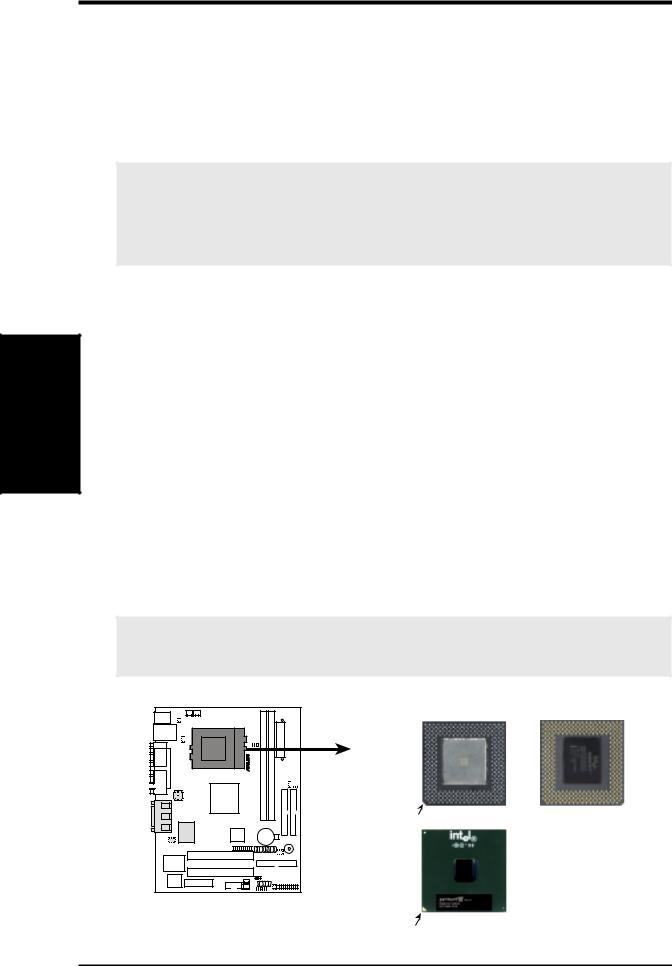
2.1.1 Specifications
• Latest Processor Support |
|
|
|
Intel Pentium® III |
100/133MHz FSB |
Coppermine core |
FC-PGA |
Intel Celeron™ |
66MHz FSB |
Coppermine core |
FC-PGA |
Intel Celeron™ |
66MHz FSB |
Mendocino core |
PPGA |
•SiS AGPset: SiS 630E AGPset with integrated SiS300 AGP graphics controller supports a 133MHz Front Side Bus (FSB) and UltraDMA/66, which allows burst mode data transfer rates of up to 66.6MB/sec.
•PC100/133 and VCM Memory Support: Equipped with two Dual Inline Memory Module (DIMM) sockets to support Intel PC100/133-compliant SDRAMs (available in 64, 128, 256, or 512MB densities) up to 1GB.
•UltraDMA/66 Support: Comes with an onboard PCI Bus Master IDE controller with two connectors that support four IDE devices on two channels. Supports UltraDMA/66, UltraDMA/33, PIO Modes 3 & 4 and Bus Master IDE DMA Mode 2, and Enhanced IDE devices, such as DVD-ROM, CD-ROM, CD-R/RW, LS-120, and Tape Backup drives.
•Form Factor for Easy-to-Use PC: Designed for small-size easy-to-use PCs, this new highly flexible form factor reduces the motherboard size by as much as 25% over the microATX design.
•More USB Ports: Supports a total of 5 USB ports for more peripheral connectivity options.
•Peripheral Wakeup: Supports Wakeup on LAN, USB, and PS/2 Mouse/Keyboard.
•SMBus: Features the System Management Bus interface, which is used to physically transport commands and information between SMBus devices.
•PC Health Monitoring: Provides an easy way to examine and manage system status information, such as CPU and systerm voltages, temperatures, and fan status through the onboard hardware ITE 8705 and the bundled ASUS PC Probe.
•AMR Slot: Audio Modem Riser slot supports a very affordable audio and/or modem riser card.
•Legacy Free: Provides two 32-bit PCI (Asynchronous PCI 2.2 compliant) with no ISA, eliminating bottlenecks and system memory management issues. All PCI slots can support Bus Master PCI cards, such as SCSI or LAN cards. (PCI supports up to 133MB/s maximum throughput.)
•Low Pin Count (LPC) Multi-I/O: Provides two high-speed UART compatible serial ports and one parallel port with EPP and ECP capabilities. UART2 can also be directed from COM2 to the Infrared Module for wireless connections.
8 |
ASUS CUSI-FX User’s Manual |

2.FEATURES
•Enhanced ACPI & Anti-Boot Virus Protection: Programmable BIOS (Flash EEPROM), offering enhanced ACPI for Windows 98/2000/Millenium compatibility, built-in firmware-based virus protection, and autodetection of most devices for virtually automatic setup.
•Smart BIOS: 2Mbit flash ROM gives a new easy-to-use interface which provides more control and protection over the motherboard. Provides Vcore and CPU/ SDRAM frequency adjustments, boot block write protection, and HD/SCSI/MO/ ZIP/CD/Floppy boot selection. Hardware random number generator supports new security software for data protection and secured Internet transactions.
•Concurrent PCI: Concurrent PCI allows multiple PCI transfers from PCI master busses to the memory and processor.
2.1.2 Specifications–Optional Components
The following onboard components are optional at the time of purchase:
•Smart Networking: Features the SiS630E 10/100Mb Fast Ethernet Controller, which supports Wired for Management, remote wake-up, and OnNow initiative to reduce Total Cost of Ownership (TCO).
•PCI Audio: Smart Audio: Provides C-Media Electronics Inc.’s CMI-8738 PCI 3D Extension Positional Audio Chip. With this chip onboard, no external CODEC is needed. CMI-8738 supports legacy audio (SB16™), FM emulator/DLS wavetable music synthesis, and HRTF 3D positional audio functions, and PCtel® HSP56 (1789) interface.Compatible with A3D™ and DirectSound™ 3D, CMI8738 thus meets PC98® requirements, and supports professional digital audio interface and 4-channel speaker.
2. FEATURES |
OptionalComponents |
|
|
ASUS CUSI-FX User’s Manual |
9 |

Performance |
2. FEATURES |
|
|
2.FEATURES
2.1.3Performance
•UltraPerformance: Onboard IDE Bus Master controller with two connectors that support four IDE devices in two channels. Supports UltraDMA/66, UltraDMA/33 (IDE DMA Mode 2), PIO Modes 3 & 4, and supports Enhanced IDE devices, such as DVD-ROM, CD-ROM, CD-R/RW, LS-120, and Tape Backup drives.
•Dual Speeds: CPU frequency can operate at either 133MHz or 100MHz.
•High-Speed Data Transfer Interface: IDE transfers using UltraDMA/33 Bus Master IDE can handle rates up to 33MB/s. This motherboard with its chipset and support for UltraDMA/66 doubles the UltraDMA/33 burst transfer rate to 66.6MB/s. UltraDMA/66 is backward compatible with both DMA/33 and DMA and with existing DMA devices and systems so there is no need to upgrade current EIDE/IDE drives and host systems. (UltraDMA/66 requires a 40-pin 80-conductor cable to be enabled and/or for UltraDMA Mode 4.)
•Concurrent PCI: Concurrent PCI allows multiple PCI transfers from PCI master buses to memory and processor.
•SDRAM Optimized Performance: This motherboard supports PC133-com- pliant Synchronous Dynamic Random Access Memory (SDRAM), which increases the data transfer rate to 1066MB/s max.
•ACPI Ready: ACPI (Advanced Configuration and Power Interface) is also implemented on all ASUS smart series motherboards. ACPI provides more Energy Saving Features for future operating systems (OS) supporting OS Direct Power Management (OSPM) functionality. With these features implemented in the OS, PCs can be ready around the clock, yet satisfy all the energy saving standards. To fully utilize the benefits of ACPI, an ACPI-supported OS, such as Windows 98/2000/Millenium, must be used.
•New Compliancy: Both the BIOS and hardware levels of the motherboard meet the stringent requirements for PC 99 certification. The new PC 99 requirements for systems and components are based on the following high-level goals: support for Plug and Play compatibility and power management for configuring and managing all system components, and 32-bit device drivers and installation procedures for Windows 95/NT and later. Color-coded connectors and descriptive icons make identification easy as required by PC 99.
10 |
ASUS CUSI-FX User’s Manual |
2.FEATURES
2.1.4Intelligence
•Fan Status Monitoring and Alarm: To prevent system overheat and system damage, the CPU, power supply, and system fans can be monitored for RPM and failure. All the fans are set for its normal RPM range and alarm thresholds.
•Temperature Monitoring and Alert: To prevent system overheat and system damage, this motherboard supports processor thermal sensing and auto-protection.
•Voltage Monitoring and Alert: System voltage levels are monitored to ensure stable current to critical motherboard components. Voltage specifications are more critical for future processors, so monitoring is necessary to ensure proper system configuration and management.
•System Resources Alert: Today’s operating systems, such as Windows 98/ Millenium, Windows NT/2000, and OS/2, require much more memory and hard drive space to present enormous user interfaces and run large applications. The onboard hardware ASUS ASIC in conjunction with either the bundled ASUS PC Probe or Intel LDCM will warn the user before the system resources are used up to prevent possible application crashes. Suggestions will give the user information on managing their limited resources more efficiently.
•Dual Function Power Button: Through BIOS, the power button can be defined as the “ Stand by” (a.k.a. Suspend or Sleep) button or as the Soft-Off (see ATX Power / Soft-Off Switch Lead in 3.8 Connectors for more information) button. Regardless of the setting, pushing the power button for more than 4 seconds will enter the Soft-Off mode.
•Remote Ring On (requires modem): This allows a computer to be turned on remotely through an internal or external modem. With this benefit on-hand, users can access any information from their computers from anywhere in the world.
•Message LED (requires ACPI OS support): Message LEDs now act as information providers. Through the way a particular LED illuminates, the user can determine if a message has been received from a fax/modem. A simple glimpse provides useful information to the user. This function requires ACPI OS and driver support.
•Peripheral Power Up: Keyboard power up can be enabled or disabled through BIOS setup to allow the computer to be powered ON using your keyboard.
FEATURES |
Intelligence |
2. |
|
|
|
ASUS CUSI-FX User’s Manual |
11 |

MB |
2. |
Components |
FEATURES |
|
|
2.FEATURES
2.2CUSI-FX Motherboard Components
See opposite page for locations.
|
|
|
Location |
Processor Support |
Socket 370 for Pentium III/Celeron Processors ....................... |
2 |
|
Chipsets |
SiS 630E 3C Integration Single Chip ....................................... |
3 |
|
|
ITE 8705 Super I/O Chipset ................................................... |
13 |
|
|
2MbitFlash BIOS ................................................................... |
12 |
|
Main Memory |
Maximum 1GB support |
4 |
|
|
2 DIMM Sockets ...................................................................... |
||
|
PC100/133 SDRAM and VCM SDRAM support |
|
|
Expansion Slots |
2 PCI Slots .............................................................................. |
14 |
|
|
1 |
PCI/AMR Share Slot ........................................................... |
11 |
System I/O |
2 IDE Connectors (UltraDMA/66 support) .............................. |
6 |
|
|
1 |
Floppy Disk Drive Connector ............................................... |
7 |
|
2 |
USB Headers (supports 3 USB ports) ................................... |
8 |
|
1 |
Serial COM2 Header ........................................................... |
10 |
|
2 |
USB Port Connectors .......................................... |
(Bottom) 20 |
|
1 |
Parallel Port Connector ............................................. |
(Top) 18 |
|
1 VGA Monitor Output Connector ......................................... |
17 |
|
|
1 |
Serial COM1 Port Connectors ............................. |
(Bottom) 19 |
|
1 |
PS/2 Mouse Connector .............................................. |
(Top) 21 |
|
1 |
PS/2 Keyboard Connector ................................... |
(Bottom) 21 |
Audio |
Cmedia 8738 PCI Audio Chipset (optional) ........................... |
15 |
|
|
1 |
Game/MIDI Connector (on audio model only) ......... |
(Top) 16 |
|
1 |
Line Out Connector (on audio model only) ........ |
(Bottom) 16 |
|
1 |
Line In Connector (on audio model only) ........... |
(Bottom) 16 |
|
1 |
Microphone Connector (on audio model only) ... |
(Bottom) 16 |
Network Features |
SiS630E Ethernet Controller |
(Top) 20 |
|
|
1 |
LAN (RJ45) Connector (optional) ............................ |
|
|
Wake-On-LAN Connector ........................................................ |
9 |
|
|
Wake-On-Ring Connector ........................................................ |
1 |
|
Power |
ATX Power Supply Connector ................................................. |
5 |
|
Form Factor |
FlexATX |
|
|
12 |
ASUS CUSI-FX User’s Manual |

2.FEATURES
2.2.1Component Locations
1 |
2 |
3 |
4 |
5 |
6 |
21
20
19
18
17
16
15
14
13
12
11 |
10 |
9 |
8 |
7 |
2. FEATURES |
ComponentLocations |
|
|
ASUS CUSI-FX User’s Manual |
13 |
3.HARDWARE SETUP
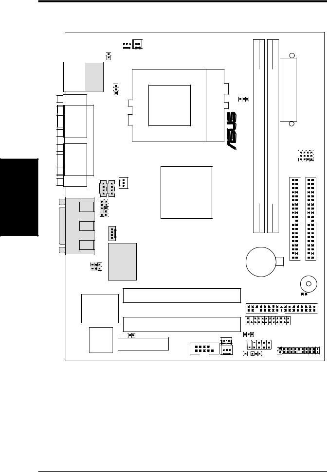
3.1CUSI-FX Motherboard Layout
Layout Motherboard
|
|
|
CPU_FAN |
|
|
WOR |
01 |
|||
|
|
PS/2 |
|
|
||||||
|
|
|
|
|
||||||
|
T: Mouse |
|
|
|
PWRTMP |
|
|
|||
|
B: Keyboard |
|
|
|
|
|
||||
|
|
|
|
|
|
|||||
|
|
|
|
|
|
|
|
|
|
|
|
Bottom: Top: |
|
|
Socket 370 |
|
module) |
module) |
||
|
USB1 |
|
USBPWR1 |
|
|
|
|||
|
RJ-45 |
|
|
|
|
|
|
||
|
USB2 |
|
|
|
|
|
|
|
|
|
COM1 |
|
|
|
|
SCPU |
1 (64/72-bit, 168-pin |
2 (64/72-bit, 168-pin |
|
|
|
|
|
|
|
||||
3SETUP.H/W |
AUDIO |
PARALLEL PORT |
|
|
|
® |
|
||
Line |
AUDIO_PANEL |
SiS630E |
|
DIMMSocket |
DIMMSocket |
||||
|
VGA |
|
PWR_FAN |
|
|
|
|||
|
|
|
|
3C |
|
|
|
||
|
|
AUX |
|
|
|
Integration |
|
|
|
|
|
Line |
|
CD1 |
|
Single |
|
|
|
|
|
Out |
|
|
|
Chip |
|
|
|
|
|
|
|
|
|
|
|
|
|
|
GAME |
In |
|
|
|
|
Row 0 1 |
2 3 |
|
|
Mic |
|
MODEM |
|
|
|
|
|
|
|
|
|
|
|
|
|
|
||
|
|
|
|
|
|
|
|
|
|
|
|
In |
|
32-bit |
|
|
|
|
|
|
|
|
|
|
|
|
|
|
|
|
|
SPDIFIN |
PCI |
|
|
CR2032 3V |
|||
|
|
Audio |
|
|
Lithium Cell |
||||
|
|
|
|
|
|
CMOS Power |
|||
|
|
SPDIFOUT Chipset |
|
|
|
|
|
||
ATXPWR
ATX Power Connector
JP3 JP2 JP1 JP0 |
Primary IDE |
Secondary IDE |
|
BUZZER |
ITE 8705 |
|
PCI Slot 1 |
|
FLOPPY |
CLRTC |
||
|
CUSI-FX |
|
|||||
|
|
|
|
||||
Super I/O |
|
|
|
|
|
|
|
2Mbit |
|
PCI Slot 2 |
|
AFPANEL |
|
||
JEN |
|
COM2 |
WOL_CON |
USBPWR0 |
|
||
Flash |
Audio Modem Riser |
|
|
|
PANEL |
||
|
USB1 |
|
|||||
BIOS |
(AMR) |
|
|
|
|||
|
|
|
|
|
|
||
|
|
|
|
CH_FAN |
USB2 |
PLED |
|
NOTE: Gray components are optional at the time of purchase.
14 |
ASUS CUSI-FX User’s Manual |

3.HARDWARE SETUP
3.2Layout Contents
Motherboard Settings
1) |
JEN |
p.16 |
JumperFree Mode Setting (Enable/Disable) |
2) |
USBPWR0/USBPWR1 |
p.17 |
USB Power Up Settings (Enable/Disable) |
3) |
FS3, FS1, FS2, FS0 |
p.18 |
CPU External Frequency Selection |
Expansion Slots
1) |
DIMM1, DIMM2 |
p.20 |
168-Pin DIMM Memory Support |
2) |
Socket 370 |
p.22 |
Central Processing Unit (CPU) |
3) |
PCI1, PCI2 |
p.23 |
32-bit PCI Bus Expansion Slots |
4) |
AMR |
p.25 |
Audio Modem Riser Slot |
Connectors
1) |
PS2KBMS |
p.26 |
PS/2 Mouse Connector (6-pin female) |
2) |
PS2KBMS |
p.26 |
PS/2 Keyboard Connector (6-pin female) |
3) |
RJ-45 |
p.27 |
Fast-Ethernet Port Connector (optional) |
4) |
USB |
p.27 |
Universal Serial Bus Ports 0 & 1 (Two 4-pin female) |
5) |
PARALLEL |
p.27 |
Parallel Port Connector (25-pin female) |
6) |
COM1/COM2 |
p.28 |
Serial Port Connectors (9 pins, 10-1 pins) |
7) |
VGA1 |
p.28 |
Monitor Port Connector (15-pin female) |
8) |
GAME_AUDIO |
p.29 |
Game/MIDI Connector (15-pin female) (optional) |
9) |
GAME_AUDIO |
p.29 |
Audio Port Connectors (Three 1/8” female) (optional) |
10) |
PRIMARY/SECONDARYIDE p.30 |
Primary/Secondary IDE Connectors (Two 40-1pins) |
|
11) |
FLOPPY |
p.30 |
Floppy Disk Drive Connector (34-1pins) |
12) |
PLED |
p.31 |
IDE Activity LED (2 pins) |
13) |
PWR_, CPU_, CH_FAN p.31 |
Power Supply, CPU, Chassis Fan Connectors (Three 3-pin) |
|
14) |
WOR |
p.32 |
Wake-On-Ring Connector (2 pins) |
15) |
WOL_CON |
p.32 |
Wake-On-LAN Connector (3 pins) |
16) |
USB1, USB2 |
p.33 |
USB Connector Set (10-1 pins, 5-1 pins) |
17) |
CD1, AUX, MODEM |
p.34 |
Internal Audio Connectors (Two 4 pins) (optional) |
18) |
AFPANEL |
p.35 |
ASUS iPanel Connector (12-1 pins) |
19) |
AAPANEL |
p.35 |
ASUS iPanel Audio Connector (12-1 pins) |
20) |
SPEAKER (PANEL) |
p.37 |
System Warning Speaker Connector (4 pins) |
21) |
KLOCK (PANEL) |
p.37 |
Keyboard Lock Switch Lead (2 pins) |
22) |
PWRLED (PANEL) |
p.37 |
System Power LED Lead (3-1 pins) |
23) |
MSG.LED (PANEL) |
p.37 |
System Message LED Lead (2 pins) |
24) |
SMI (PANEL) |
p.37 |
System Management Interrupt Switch Lead (2 pins) |
25) |
PWRSW (PANEL) |
p.37 |
ATX Power / Soft-Off Switch Lead (2 pins) |
26) |
RESET (PANEL) |
p.37 |
Reset Switch Lead (2 pins) |
27) |
ATXPWR |
p.38 |
ATX Power Supply Connector (20 pins) |
28) |
PWRTMP |
p.38 |
Power Supply Thermal Sensor Connector (2 pins) |
Layout Contents
3. H/W SETUP
ASUS CUSI-FX User’s Manual |
15 |
Settings Motherboard
SETUP H/W .3
3.HARDWARE SETUP
3.3Hardware Setup Procedure
Before using your computer, you must complete the following steps:
•Check Motherboard Settings
•Install Memory Modules
•Install the Central Processing Unit (CPU)
•Install Expansion Cards
•Connect Ribbon Cables, Panel Wires, and Power Supply
3.4Motherboard Settings
This section explains in detail how to change your motherboard’s function settings through the use of switches and/or jumpers.
WARNING! Computer motherboards and expansion cards contain very delicate Integrated Circuit (IC) chips. To protect them against damage from static electricity, you should follow some precautions whenever you work on your computer.
1.Unplug your computer when working on the inside.
2.Use a grounded wrist strap before handling computer components. If you do not have one, touch both of your hands to a safely grounded object or to a metal object, such as the power supply case.
3.Hold components by the edges and try not to touch the IC chips, leads or connectors, or other components.
4.Place components on a grounded antistatic pad or on the bag that came with the component whenever the components are separated from the system.
5.Ensure that the ATX power supply is switched off before you plug in or remove the ATX power connector on the motherboard.
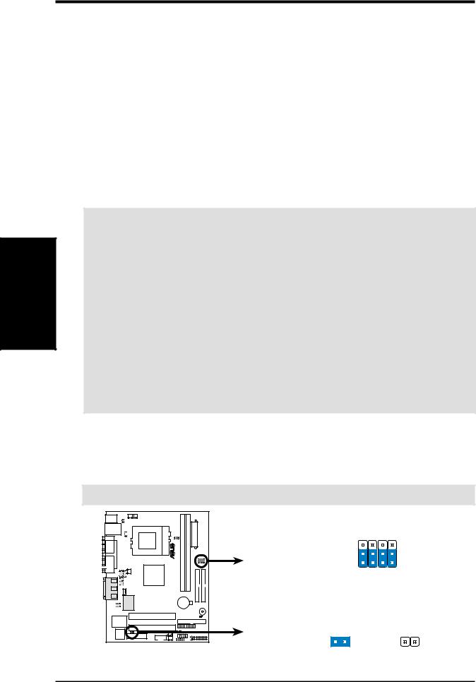
1)JumperFree™ Mode (JEN)
This jumper allows you to enable or disable the JumperFree™ mode. The JumperFree™ mode allows processor settings to be made through the BIOS setup (see 4.4 Advanced Menu)
IMPORTANT: In JumperFree mode, all DIP switches must be set to [1-2].
01 |
|
|
|
JP3 |
JP1 |
JP2 |
JP0 |
® |
|
|
|
3 |
|
|
|
2 |
|
|
|
1 |
|
|
|
JEN
CUSI-FX |
Jumperless Mode |
Jumper Mode |
||
|
1 |
2 |
1 |
2 |
CUSI-FX JumperFree™ Mode Setting
16 |
ASUS CUSI-FX User’s Manual |
3.HARDWARE SETUP
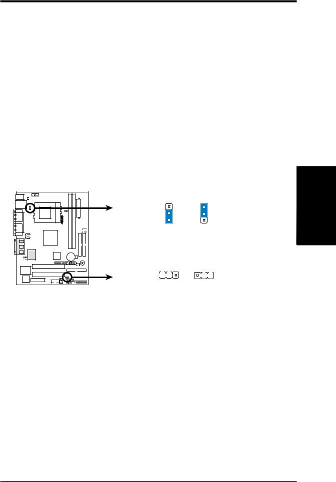
2)USB Device Wake Up (USBPWR0, USBPWR1)
These jumpers allow you to enable or disable the USB device power up function for USB devices connected to your system.This feature requires an ATX power supply that can supply at least 2A on the +5VSB lead. The default is set to Disable because not all computers have the appropriate ATX power supply. Your computer will not power ON if you set these to Enable and do not have the appropriate ATX power supply.
NOTES:
1.These two jumpers must be set in unison; that is, either both must be set to
Disable or both to Enable.
2.These settings must also be set in conjunction with Wake On USB Device in
4.5.1Power Up Control.
Setting |
USBPWR0/USBPWR1 |
||
Enable |
[1-2] |
|
|
Disable |
[2-3] |
(default) |
|
|
1 |
0 |
|
|
CUSI-FX |
|
|
CUSI-FX USB Device Wake Up
USBPWR1
2 |
3 |
2 |
|
1 |
|
Enable Disable
(Default)
USBPWR0
1 |
2 |
2 |
3 |
|
|
|
|
|
|
Enable Disable
(Default)
.3 SETUPH/W
Motherboard Settings
ASUS CUSI-FX User’s Manual |
17 |
Settings Motherboard
SETUP H/W .3
3.HARDWARE SETUP
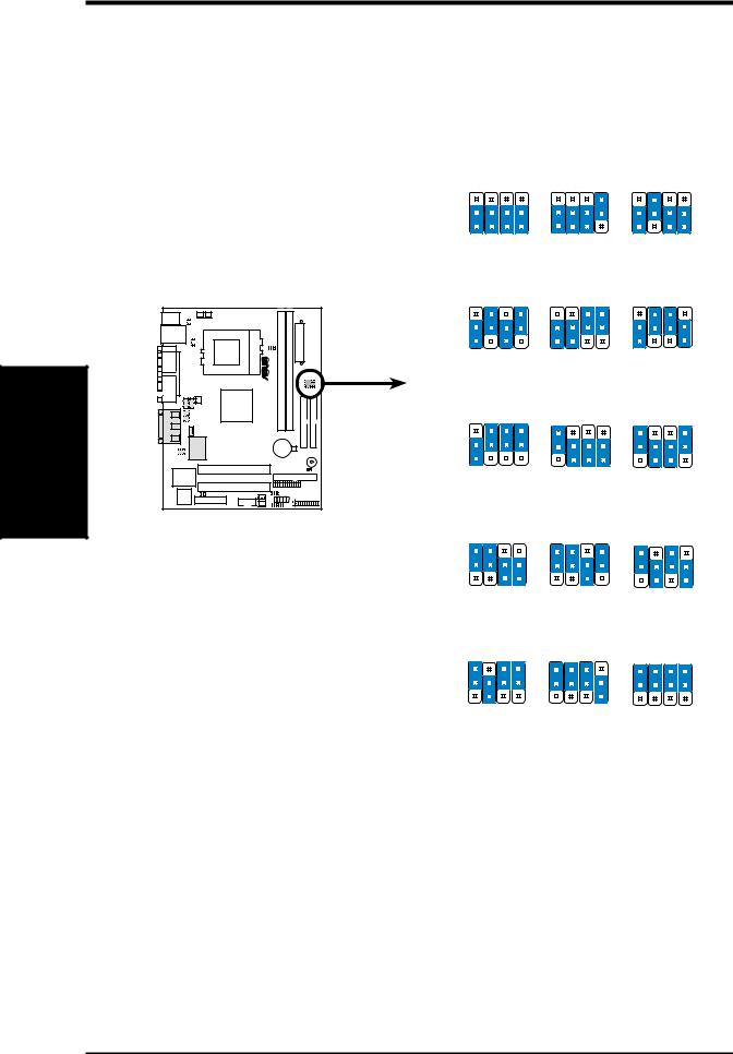
3)CPU External Frequency Setting (JP3, JP1, JP2, JP0)
This option tells the clock generator what frequency to send to the CPU, SDRAM, and the chipset. This allows the selection of the CPU’s External frequency. The CPU External Frequency multiplied by the Frequency Multiple equals the CPU’s Internal frequency (the advertised CPU speed).
|
JP3 JP1 JP2 JP0 |
JP3 JP1 JP2 JP0 |
JP3 JP1 JP2 JP0 |
3 |
|
|
|
2 |
|
|
|
1 |
|
|
|
CPU |
66.6MHz |
100.0MHz |
150.0MHz |
SDRAM |
100.0MHz |
100.0MHz |
100.0MHz |
PCI |
33.3MHz |
33.3MHz |
37.5MHz |
|
JP3 JP1 JP2 JP0 |
JP3 JP1 JP2 JP0 |
JP3 JP1 JP2 JP0 |
01 |
3 |
|
|
|
2 |
|
1 |
® |
CPU |
133.3MHz |
100.0MHz |
100.0MHz |
|
SDRAM |
100.0MHz |
133.3MHz |
150.0MHz |
|
PCI |
33.3MHz |
33.3MHz |
37.5MHz |
|
|
JP3 JP1 JP2 JP0 |
JP3 JP1 JP2 JP0 |
JP3 JP1 JP2 JP0 |
3 |
2 |
1 |
CUSI-FX |
CPU |
133.3MHz |
66.8MHz |
97.0MHz |
|
SDRAM |
133.3MHz |
66.8MHz |
97.0MHz |
|
PCI |
33.3MHz |
33.4MHz |
32.3MHz |
CUSI-FX CPU |
|
JP3 JP1 JP2 JP0 |
JP3 JP1 JP2 JP0 |
JP3 JP1 JP2 JP0 |
External Frequency Selection |
3 |
|
|
|
|
|
|
|
|
|
2 |
|
|
|
|
1 |
|
|
|
|
CPU |
70.0MHz |
95.0MHz |
95.0MHz |
|
SDRAM |
105.0MHz |
95.0MHz |
126.7MHz |
|
PCI |
35.0MHz |
31.7MHz |
31.7MHz |
|
|
JP3 JP1 JP2 JP0 |
JP3 JP1 JP2 JP0 |
JP3 JP1 JP2 JP0 |
|
3 |
|
|
|
|
2 |
|
|
|
|
1 |
|
|
|
|
CPU |
112.0MHz |
97.0MHz |
96.2MHz |
|
SDRAM |
112.0MHz |
129.3MHz |
96.2MHz |
|
PCI |
37.3MHz |
32.2MHz |
32.1MHz |
18 |
ASUS CUSI-FX User’s Manual |

3. HARDWARE SETUP
Manual CPU Settings (NOTE: JumperFree mode must be disabled.)
Set the jumpers according to the internal speed of your processor as follows:
CPU |
SDRAM |
Frequency Selection Switches |
|||
(MHz) |
(MHz) |
JP3 |
JP1 |
JP2 |
JP0 |
|
|
|
|
|
|
66 |
100 |
[1-2] |
[1-2] |
[1-2] |
[1-2] |
100 |
100 |
[1-2] |
[1-2] |
[1-2] |
[2-3] |
150 |
100 |
[1-2] |
[2-3] |
[1-2] |
[1-2] |
133 |
100 |
[1-2] |
[2-3] |
[1-2] |
[2-3] |
100 |
133 |
[1-2] |
[1-2] |
[2-3] |
[2-3] |
100 |
150 |
[1-2] |
[2-3] |
[2-3] |
[1-2] |
133 |
133 |
[1-2] |
[2-3] |
[2-3] |
[2-3] |
66 |
66 |
[2-3] |
[1-2] |
[1-2] |
[1-2] |
97 |
97 |
[2-3] |
[1-2] |
[1-2] |
[2-3] |
70 |
105 |
[2-3] |
[2-3] |
[1-2] |
[1-2] |
95 |
95 |
[2-3] |
[2-3] |
[1-2] |
[2-3] |
95 |
126 |
[2-3] |
[1-2] |
[2-3] |
[1-2] |
112 |
112 |
[2-3] |
[1-2] |
[2-3] |
[2-3] |
97 |
129 |
[2-3] |
[2-3] |
[2-3] |
[1-2] |
96 |
96 |
[2-3] |
[2-3] |
[2-3] |
[2-3] |
For updated processor settings, visit ASUS’s web site (see ASUS CONTACT INFORMATION).
WARNING! Premature wearing of the processor may result when overclocking. Be sure that the DIMM you use can handle the specified SDRAM MHz or else bootup will not be possible.
.3 SETUPH/W
Motherboard Settings
ASUS CUSI-FX User’s Manual |
19 |

Memory System
.3 SETUP H/W
3.HARDWARE SETUP
3.5System Memory (DIMM)
NOTE: No hardware or BIOS setup is required after adding or removing memory.
This motherboard uses only Dual Inline Memory Modules (DIMMs). Sockets are available for 3.3Volt (power level) unbuffered Synchronous Dynamic Random Access Memory (SDRAM) of 16, 32, 64, 128MB, 256 or 512MB. to form a memory size between 16MB and 1.5GB. One side (with memory chips) of the DIMM takes up one row on the motherboard. This motherboard also supports NEC’s Virtual Channel (VC) SDRAMs.
To use the chipset’s Error Checking and Correction (ECC) feature, you must use a DIMM with 9 chips per side (standard 8 chips/side + 1 ECC chip).
Memory speed setup is recommended through Configure SDRAM Timing by SPD
(see 4.4.2 Advanced Chipset Setup).
Install memory in any combination as follows:
IMPORTANT
•For optimum signal integrity, inserting the DIMMs in the following order is recommended: DIMM1, DIMM2
•SDRAMs used must be compatible with the current PC133/PC100 SDRAM specification.
•DO NOT mix SDRAMs with VC SDRAMs.
Location |
168-pin DIMM |
Total Memory |
DIMM1 (Rows 0&1) SDRAM 16, 32, 64, 128, 256, 512MB |
x1 |
|
|
|
|
DIMM2 (Rows 2&3) SDRAM 16, 32, 64, 128, 256, 512MB |
x1 |
|
|
|
|
|
Total System Memory (Max 1GB) |
= |
|
|
|
3.5.1 General DIMM Notes
•This motherboard supports SPD (Serial Presence Detect) DIMMs. This is the memory of choice for best performance vs. stability.
•This motherboard does NOT support registered memory.
•SDRAM chips are generally thinner with higher pin density than EDO (Extended Data Output) chips.
•BIOS shows SDRAM memory on bootup screen.
•Single-sided DIMMs come in 16, 32, 64,128, 256MB; double-sided come in 32, 64, 128, 256, 512MB.
20 |
ASUS CUSI-FX User’s Manual |
3.HARDWARE SETUP
3.5.2DIMM Memory Installation
Insert the module(s) as shown. Because the number of pins are different on either side of the breaks, the module will only fit in the orientation shown. DIMM modules are longer and have different pin contact on each side and therefore have a higher pin density. SIMM modules have the same pin contact on both sides.
01 |
CUSI-FX |
CUSI-FX 168-Pin DIMM Sockets
Lock
88 Pins
60 Pins
20 Pins
The DIMMs must be 3.3V Unbuffered for this motherboard. To determine the DIMM type, check the notches on the DIMMs (see figure below).
168-Pin DIMM Notch Key Definitions (3.3V)
.3 SETUPH/W
System Memory
|
|
|
|
|
|
|
|
|
|
|
|
|
|
|
|
|
|
|
|
|
|
|
|
|
|
|
|
|
|
DRAM Key Position |
Voltage Key Position |
|||
RFU |
Unbuffered |
5.0V |
Reserved |
Buffered |
|
3.3V |
|
The notches on the DIMM module will shift between left, center, or right to identify the type and also to prevent the wrong type from being inserted into the DIMM slot on the motherboard. You must ask your retailer the correct DIMM type before purchasing. This motherboard supports four clock signals.
ASUS CUSI-FX User’s Manual |
21 |
CPU
.3 SETUP H/W
3.HARDWARE SETUP
3.6Central Processing Unit (CPU)
The motherboard provides a ZIF Socket 370. The CPU that came with the motherboard should have a fan attached to it to prevent overheating. If this is not the case, then purchase a fan before you turn on your system.
WARNING! Be sure that there is sufficient air circulation across the processor’s heatsink by regularly checking that your CPU fan is working. Without sufficient circulation, the processor could overheat and damage both the processor and the motherboard. You may install an auxiliary fan, if necessary.
To install a CPU, first turn off your system and remove its cover. Locate the ZIF socket and open it by first pulling the lever sideways away from the socket then upwards to a 90-degree angle. Insert the CPU with the correct orientation as shown. The notched corner should point towards the end of the lever. Because the CPU has a corner pin for two of the four corners, the CPU will only fit in the orientation as shown. The picture is for reference only; you should have a CPU fan that covers the face of the CPU. With the added weight of the CPU fan, no force is required to insert the CPU. Once completely inserted, close the socket’s lever while holding down the CPU. After the CPU is , install an Intel recommended fan heatsink. Locate the CPU fan connector (see 3.1 Motherboard Layout or 3.8 Connectors) and connect the CPU fan cable to it.
NOTE: Do not forget to set the correct Bus Frequency and Multiple (frequency multiple setting is available only on unlocked processors) for your Socket 370 processor or else boot-up may not be possible. Socket 370 processors provide internal thermal sensing so that a socket mounted thermal resistor is not needed.
CAUTION! Be careful not to scrape the motherboard when mounting a clampstyle processor fan or else damage may occur to the motherboard.
|
|
Socket 370 CPU |
Socket 370 CPU |
1 |
0 |
(Top) |
(Bottom) |
|
Notch |
Celeron |
|
CUSI-FX |
|
|
|
CUSI-FX Socket 370 |
Pentium III |
|
|
|
Gold Arrow |
|
|
|
|
|
|
22 |
ASUS CUSI-FX User’s Manual |

3.HARDWARE SETUP
3.7Expansion Cards
WARNING! Unplug your power supply when adding or removing expansion cards or other system components. Failure to do so may cause severe damage to both your motherboard and expansion cards.
3.7.1 Expansion Card Installation Procedure
1.Read the documentation for your expansion card and make any necessary hardware or software settings for your expansion card, such as jumpers.
2.Remove your computer system’s cover and the bracket plate on the slot you intend to use. Keep the bracket for possible future use.
3.Carefully align the card’s connectors and press firmly.
4.Secure the card on the slot with the screw you removed above.
5.Replace the computer system’s cover.
6.Set up the BIOS if necessary
(such as IRQ xx Used By ISA: Yes in PNP AND PCI SETUP)
7.Install the necessary software drivers for your expansion card.
3.7.2 Assigning IRQs for Expansion Cards
Some expansion cards need an IRQ to operate. Generally, an IRQ must be exclusively assigned to one use. In a standard design, there are 16 IRQs available but most of them are already in use, leaving 6 IRQs free for expansion cards. If your motherboard has PCI audio onboard, an additional IRQ will be used. If your motherboard also has MIDI enabled, another IRQ will be used, leaving 4 IRQs free.
.3 SETUPH/W
Expansion Cards
ASUS CUSI-FX User’s Manual |
23 |

3Expansion
H/W .
SETUPCards
3. HARDWARE SETUP
The following table lists the default IRQ assignments for standard PC devices. Use this table when configuring your system and for resolving IRQ conflicts.
Standard Interrupt Assignments
IRQ |
Priority |
Standard Function |
0 |
1 |
System Timer |
|
|
|
1 |
2 |
Keyboard Controller |
|
|
|
2 |
N/A |
Programmable Interrupt |
|
|
|
3* |
11 |
Communications Port (COM2) |
|
|
|
4* |
12 |
Communications Port (COM1) |
|
|
|
5* |
13 |
Sound Card (sometimes LPT2) |
|
|
|
6 |
14 |
Floppy Disk Controller |
|
|
|
7* |
15 |
Printer Port (LPT1) |
|
|
|
8 |
3 |
System CMOS/Real Time Clock |
|
|
|
9* |
4 |
ACPI Mode when enabled |
|
|
|
10* |
5 |
IRQ Holder for PCI Steering |
|
|
|
11* |
6 |
IRQ Holder for PCI Steering |
|
|
|
12* |
7 |
PS/2 Compatible Mouse Port |
|
|
|
13 |
8 |
Numeric Data Processor |
|
|
|
14* |
9 |
Primary IDE Channel |
|
|
|
15* |
10 |
Secondary IDE Channel |
*These IRQs are usually available for ISA or PCI devices.
Interrupt Request Table for this Motherboard
Interrupt requests are shared as shown by the following table:
|
INT-A |
INT-B |
|
INT-C |
INT-D |
PCI slot 1 |
shared |
— |
|
— |
— |
|
|
|
|
|
|
PCI slot 2 |
— |
shared |
|
— |
— |
|
|
|
|
|
|
Onboard VGA |
shared |
— |
|
— |
— |
|
|
|
|
|
|
Onboard LAN |
— |
— |
|
shared |
— |
|
|
|
|
|
|
Onboard USB controller |
— |
— |
— |
|
not shared |
|
|
|
|
|
|
Onboard Audio |
— |
— |
|
shared |
— |
|
|
|
|
|
|
AMR |
— |
shared |
|
— |
— |
|
|
|
|
|
|
IMPORTANT: If using PCI cards on shared slots, make sure that the drivers support “ Share IRQ” or that the cards do not need IRQ assignments. Conflicts will arise between the two PCI groups that will make the system unstable or cards inoperable.
24 |
ASUS CUSI-FX User’s Manual |
3.HARDWARE SETUP
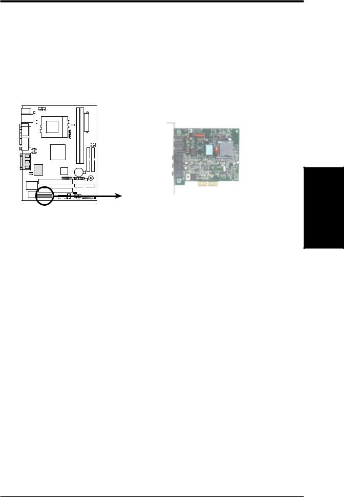
3.7.3Audio Modem Riser (AMR) Slot
This connector supports a specially designed audio and/or modem card called anAMR. Main processing is done through software and controlled by the motherboard’s system chipset. This provides an upgradeable audio and/or modem solution at an incredibly low cost. The motherboard’s onboard CODEC (optional) must be disabled when using an AMR.
NOTE: An AMR is not included with this motherboard.
01 |
CUSI-FX |
CUSI-FX Audio Modem Riser (AMR) Connector
Expansion Cards
3. H/W SETUP
ASUS CUSI-FX User’s Manual |
25 |
.3
H/WConnectors SETUP
3.HARDWARE SETUP
3.8Connectors
WARNING! Some pins are used for connectors or power sources. These are clearly distinguished from jumpers in the Motherboard Layout. Placing jumper caps over these connector pins will cause damage to your motherboard.
IMPORTANT: Ribbon cables should always be connected with the red stripe to Pin 1 on the connectors. Pin 1 is usually on the side closest to the power connector on hard drives and CD-ROM drives, but may be on the opposite side on floppy disk drives. Check the connectors before installation because there may be exceptions. IDE ribbon cable must be less than 46 cm (18 in.), with the second drive connector no more than 15 cm (6 in.) from the first connector.
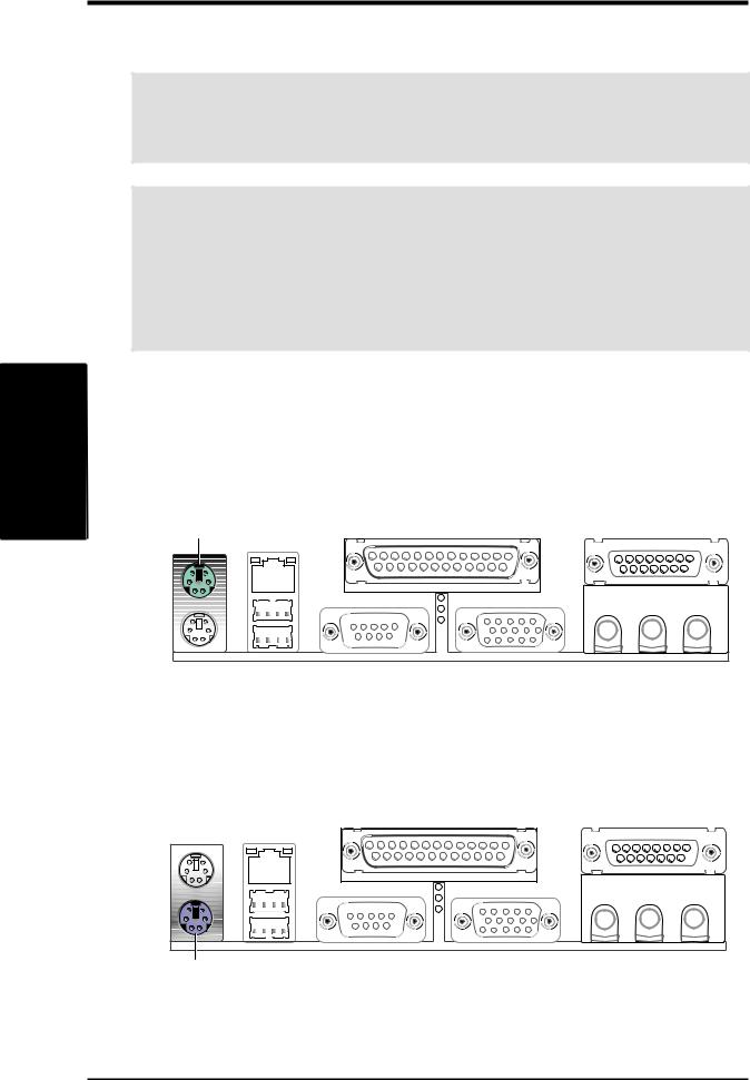
1)PS/2 Mouse Connector (Green 6-pin PS2KBMS)
The system will direct IRQ12 to the PS/2 mouse if one is detected. If one is not detected, expansion cards can use IRQ12. See PS/2 Mouse Function Control in 4.4 Advanced Menu.
PS/2 Mouse (6-pin female)
2)PS/2 Keyboard Connector (Purple 6-pin PS2KBMS)
This connection is for a standard keyboard using an PS/2 plug (mini DIN). This connector will not allow standard AT size (large DIN) keyboard plugs. You may use a DIN to mini DIN adapter on standard AT keyboards.
PS/2 Keyboard (6-pin female)
26 |
ASUS CUSI-FX User’s Manual |
3.HARDWARE SETUP
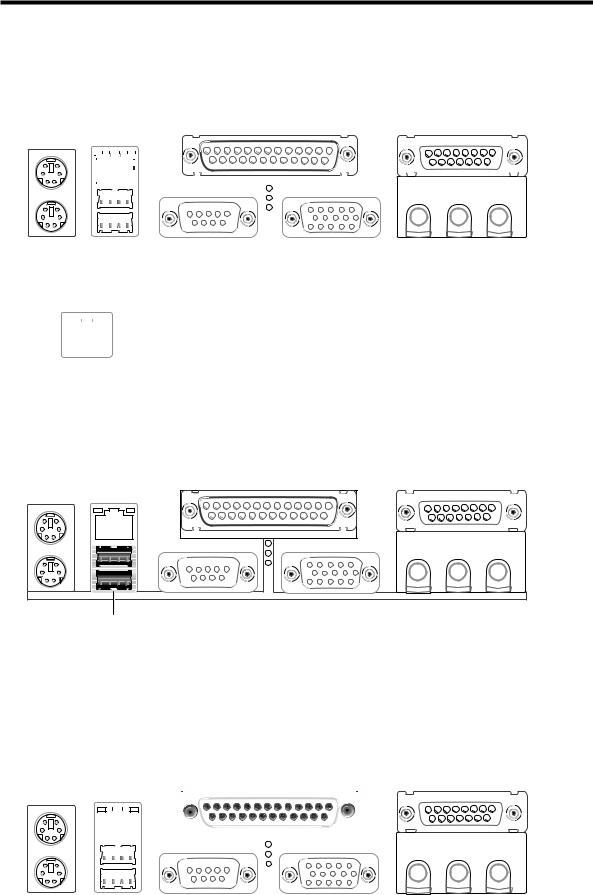
3)Fast-Ethernet Port Connector (RJ45) (optional)
An optional RJ-45 connector is located on top of the USB connectors. The connector allows the motherboard to connect to a Local Area Network (LAN) through a network hub.
RJ-45
|
|
|
|
|
|
|
|
|
|
|
|
|
|
|
|
|
|
|
|
|
|
|
|
|
|
|
|
|
|
|
|
|
|
|
|
|
|
|
|
|
|
|
|
|
|
|
|
|
|
|
|
|
|
|
|
|
|
|
|
|
|
|
|
|
|
|
|
|
|
|
|
|
|
|
|
|
|
|
|
|
|
|
|
|
|
|
|
|
|
|
|
|
|
|
|
|
|
|
|
|
|
|
|
|
|
|
|
|
|
|
|
|
|
|
|
|
|
|
|
|
|
|
|
|
|
|
|
|
|
|
|
|
|
|
|
|
|
|
|
|
|
|
|
|
|
|
|
|
|
|
|
|
|
|
|
|
|
|
|
|
|
|
|
|
|
|
|
|
|
|
|
|
|
|
|
|
|
|
|
|
|
|
|
|
|
|
|
|
|
|
|
|
|
|
|
|
|
|
|
|
|
|
|
|
|
|
|
|
|
|
|
|
|
|
|
|
|
|
|
|
|
|
|
|
|
|
|
|
|
|
|
|
|
|
|
|
|
|
|
|
|
|
|
|
|
|
|
|
|
|
|
|
|
|
|
|
|
|
|
|
|
|
|
|
|
|
|
|
|
|
|
|
|
|
|
|
|
|
|
|
|
|
|
|
|
|
|
|
|
|
|
|
|
|
|
|
|
|
|
|
|
|
|
|
|
|
|
|
|
|
|
|
|
|
|
|
|
|
|
|
|
|
|
|
|
|
|
|
|
|
|
|
|
|
|
|
|
|
|
|
|
|
|
|
|
|
|
|
|
|
|
|
|
|
|
|
|
|
|
|
|
|
|
|
|
|
|
|
|
|
|
|
|
|
|
|
|
|
|
|
|
|
|
|
|
|
|
|
|
|
|
|
|
|
|
|
|
|
|
|
|
|
|
|
|
|
LED1 |
|
|
LED2 |
|
|
|
|
|
|
LED1 |
|
|
LED2 |
|||||||||||||||||||||||
|
|
|
|
|
|
|
|
|
|
|
|
|
|
|
|
|
|
|
|
|
|
|
|
|
|
|
|
|
|
|
|
|
|
|
|
|
|
|
|
|
|
|
|
|
|
|
|
|
|
|
|
|
|
|
|
|
|
|
|
On |
|
|
Power |
|
|
Good connection |
|||||||
|
|
|
|
|
|
|
|
|
|
|
|
|
|
|
|
|
|
|
|
|
|
|
Off |
|
|
No power |
|
|
Bad connection |
|||||||
|
|
|
|
|
|
|
|
|
|
|
|
|
|
|
|
|
|
|
|
|
|
|
|
|
|
|
||||||||||
|
|
|
|
|
|
|
|
|
|
|
|
|
|
|
|
|
|
|
|
|||||||||||||||||
|
|
|
|
|
|
|
|
|
|
|
|
|
|
|
|
|
|
|
|
|
Blinking |
|
|
Data transfer |
|
|
|
|
|
|
||||||
|
|
|
|
|
|
|
|
|
|
|
|
|
|
|
|
|
|
|
|
|
|
|
|
|
|
|||||||||||
|
|
|
|
|
|
|
|
|
|
|
|
|
|
|
|
|
|
|
|
|
|
|
|
|
|
|
|
|
|
|
|
|
|
|
|
|
4)Universal Serial Bus Ports 0 & 1 (Black two 4-pin USB)
Two USB ports are available for connecting USB devices.
H/WSETUP |
Connectors |
3. |
|
|
|
Universal Serial Bus (USB)
5)Parallel Port Connector (Burgundy 25-pin PRINTER)
You can enable the parallel port and choose the IRQ through Onboard Parallel Port (see 4.4.2 I/O Device Configuration).
NOTE: Serial printers must be connected to the serial port.
Parallel (Printer) Port (25-pin female)
|
|
|
|
|
|
|
|
|
|
|
|
|
|
|
|
|
|
|
|
|
|
|
|
|
|
|
|
|
|
|
|
|
|
|
|
|
|
|
|
|
|
|
|
|
|
|
|
|
|
|
|
|
|
|
|
|
|
|
|
|
|
|
|
|
|
|
|
|
|
|
|
|
|
|
|
|
|
|
|
|
|
|
|
|
|
|
|
|
|
|
|
|
|
|
|
|
|
|
|
|
|
|
|
|
|
|
|
|
|
|
|
|
|
|
|
|
|
|
|
|
|
|
|
|
|
|
|
|
|
|
|
|
|
|
|
|
|
|
|
|
|
|
|
|
|
|
|
|
|
|
|
|
|
|
|
|
|
|
|
|
|
|
|
|
|
|
|
|
|
|
|
|
|
|
|
|
|
|
|
|
|
|
|
|
|
|
|
|
|
|
|
|
|
|
|
|
|
|
|
|
|
|
|
|
|
|
|
|
|
|
|
|
|
|
|
|
|
|
|
|
|
|
|
|
|
|
|
|
|
|
|
|
|
|
|
|
|
|
|
|
|
|
|
|
|
|
|
|
|
|
|
|
|
|
|
|
|
|
|
|
|
|
|
|
|
|
|
|
|
|
|
|
|
|
|
|
|
|
|
|
|
|
|
|
|
|
|
|
|
|
|
|
|
|
|
|
|
|
|
|
|
|
|
|
|
|
|
|
|
|
|
|
|
|
|
|
|
|
|
|
|
|
|
|
|
|
|
|
|
|
|
|
|
|
|
|
|
|
|
|
|
|
|
|
|
|
|
|
|
|
|
|
|
|
|
|
|
|
|
|
|
|
|
|
|
|
|
|
|
|
|
|
|
|
|
|
|
|
|
|
|
|
|
|
|
|
|
|
|
|
|
|
|
|
|
|
|
|
|
|
|
|
|
|
|
|
|
|
|
|
|
|
|
|
|
|
|
|
|
|
|
|
|
|
|
|
|
|
|
|
|
|
|
|
|
|
|
|
|
|
|
|
|
|
|
|
|
ASUS CUSI-FX User’s Manual |
27 |
||||||||||||
3.HARDWARE SETUP
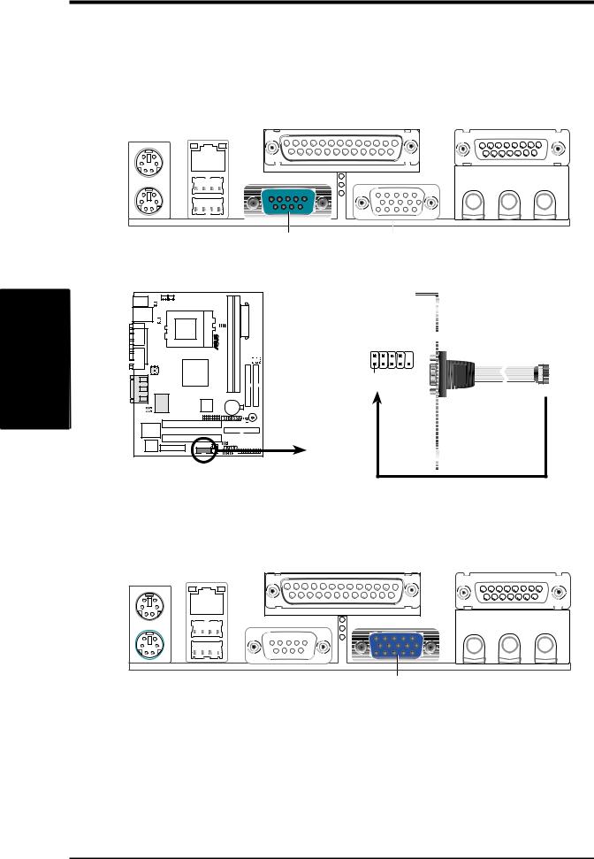
6)Serial Port Connectors (Teal/Turquoise 9-pin COM1)
One serial port is ready for a mouse or other serial devices. A second serial port is available using a serial port bracket connected from the motherboard to an expansion slot opening. See Onboard Serial Port 1 in 4.2.2 I/O Device Configuration for settings.
COM 1
Serial Port (9-pin male)
.3
H/WConnectors SETUP
01 |
CUSI-FX |
COM2 
Pin 1
CUSI-FX Serial Port Header
7)Monitor Output Connector (Blue 15-pin VGA1)
This connector is for output to a VGA-compatible device.
VGA Monitor (15-pin female)
28 |
ASUS CUSI-FX User’s Manual |
3.HARDWARE SETUP
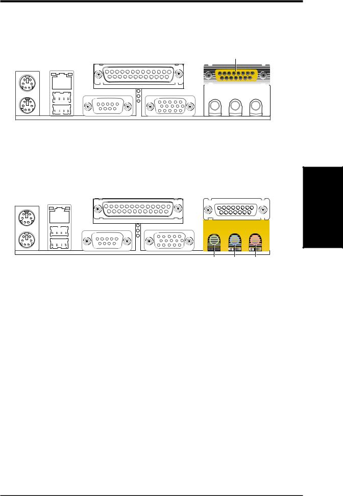
8)Game/MIDI Connector (Gold 15-pin GAME_AUDIO) (optional)
You may connect game joysticks or game pads to this connector for playing games. Connect MIDI devices for playing or editing professional audio.
Game/MIDI (15-pin female)
9) Audio Port Connectors (Three 1/8” GAME_AUDIO) (optional)
Line Out (lime) can be connected to headphones or preferably powered speakers. Line In (light blue) allows tape players or other audio sources to be re-
corded by your computer or played through the Line Out (lime). Mic (pink) |
ChannelsConnectorsDMA |
SETUPH/W3. |
|
allows microphones to be connected for inputting voice. |
|
Line Out Line In Mic |
|
1/8" Stereo Audio Connectors |
|
ASUS CUSI-FX User’s Manual |
29 |
.3
H/WConnectors SETUP
3.HARDWARE SETUP
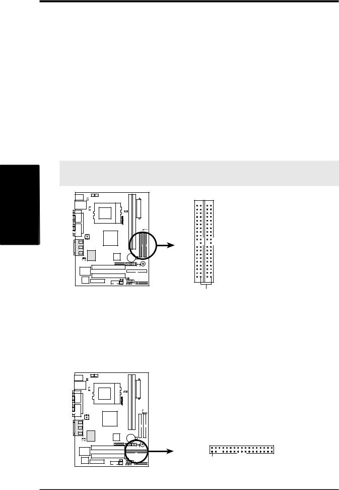
10)Primary (Blue) / Secondary IDE Connectors (Two 40-1pin IDE)
These connectors support the provided UltraDMA/66 IDE hard disk ribbon cable. Connect the cable’s blue connector to the motherboard’s primary (recommended) or secondary IDE connector, and then connect the gray connector to your UltraDMA/66 slave device (hard disk drive) and the black connector to your UltraDMA/66 master device. It is recommended that non-UltraDMA/66 devices be connected to the secondary IDE connector. If you install two hard disks, you must configure the second drive to Slave mode by setting its jumper accordingly. Please refer to your hard disk documentation for the jumper settings. BIOS now supports specific device bootup (see 4.4.1 Advanced CMOS Setup). (Pin
20 is removed to prevent inserting in the wrong orientation when using ribbon cables with pin 20 plugged).
TIP: You may configure two hard disks to be both Masters with two ribbon cables –one for the primary IDE connector and another for the secondary IDE connector. You may install one operating system on an IDE drive and another on a SCSI drive and select the boot disk through 4.4.1 Advanced CMOS Setup.
IMPORTANT: UltraDMA/66 IDE devices must use a 40-pin 80-conductor IDE cable for 66MBytes/s transfer rates.
01 |
|
|
CUSI-FX |
PrimaryIDE Connector |
SecondaryIDE Connector |
CUSI-FX IDE Connectors |
|
PIN 1 |
|
|
NOTE: Orient the red markings on the IDE ribbon cable to PIN 1
11)Floppy Disk Drive Connector (34-1pin FLOPPY)
This connector supports the provided floppy drive ribbon cable. After connecting the single end to the board, connect the two plugs on the other end to the floppy drives. (Pin 5 is removed to prevent inserting in the wrong orientation when using ribbon cables with pin 5 plugged).
01 |
CUSI-FX |
NOTE: Orient the red markings on the floppy ribbon cable to PIN 1.
PIN 1
CUSI-FX Floppy Disk Drive Connector
30 |
ASUS CUSI-FX User’s Manual |
 Loading...