


 Loading...
B250 MINING EXPERT
Motherboard

E13594
Second Edition
November 2017
Copyright © 2017 ASUSTeK COMPUTER INC. All Rights Reserved.
No part of this manual, including the products and software described in it, may be reproduced, transmitted, transcribed, stored in a retrieval system, or translated into any language in any form or by any means, except documentation kept by the purchaser for backup purposes, without the express written permission of ASUSTeK COMPUTER INC. (“ASUS”).
Product warranty or service will not be extended if: (1) the product is repaired, modified or altered, unless such repair, modification of alteration is authorized in writing by ASUS; or (2) the serial number of the product is defaced or missing.
ASUS PROVIDES THIS MANUAL “AS IS” WITHOUT WARRANTY OF ANY KIND, EITHER EXPRESS OR IMPLIED, INCLUDING BUT NOT LIMITED TO THE IMPLIED WARRANTIES OR CONDITIONS OF MERCHANTABILITY OR FITNESS FOR A PARTICULAR PURPOSE. IN NO EVENT SHALL ASUS, ITS DIRECTORS, OFFICERS, EMPLOYEES OR AGENTS BE LIABLE FOR ANY INDIRECT, SPECIAL, INCIDENTAL, OR CONSEQUENTIAL DAMAGES (INCLUDING DAMAGES FOR LOSS OF PROFITS, LOSS OF BUSINESS, LOSS OF USE OR DATA, INTERRUPTION OF BUSINESS AND THE LIKE), EVEN IF ASUS HAS BEEN ADVISED OF THE POSSIBILITY OF SUCH DAMAGES ARISING FROM ANY DEFECT OR ERROR IN THIS MANUAL OR PRODUCT.
SPECIFICATIONS AND INFORMATION CONTAINED IN THIS MANUAL ARE FURNISHED FOR INFORMATIONAL USE ONLY, AND ARE SUBJECT TO CHANGE AT ANY TIME WITHOUT NOTICE, AND SHOULD NOT BE CONSTRUED AS A COMMITMENT BY ASUS. ASUS ASSUMES NO RESPONSIBILITY OR LIABILITY FOR ANY ERRORS OR INACCURACIES THAT MAY APPEAR IN THIS MANUAL, INCLUDING THE PRODUCTS AND SOFTWARE DESCRIBED IN IT.
Products and corporate names appearing in this manual may or may not be registered trademarks or copyrights of their respective companies, and are used only for identification or explanation and to the owners’ benefit, without intent to infringe.
Offer to Provide Source Code of Certain Software
This product contains copyrighted software that is licensed under the General Public License (“GPL”), under the Lesser General Public License Version (“LGPL”) and/or other Free Open Source Software Licenses. Such software in this product is distributed without any warranty to the extent permitted by the applicable law. Copies of these licenses are included in this product.
Where the applicable license entitles you to the source code of such software and/or other additional data, you may obtain it for a period of three years after our last shipment of the product, either
(1)for free by downloading it from http://support.asus.com/download
or
(2)for the cost of reproduction and shipment, which is dependent on the preferred carrier and the location where you want to have it shipped to, by sending a request to:
ASUSTeK Computer Inc.
Legal Compliance Dept.
15 Li Te Rd.,
Beitou, Taipei 112
Taiwan
In your request please provide the name, model number and version, as stated in the About Box of the product for which you wish to obtain the corresponding source code and your contact details so that we can coordinate the terms and cost of shipment with you.
The source code will be distributed WITHOUT ANY WARRANTY and licensed under the same license as the corresponding binary/object code.
This offer is valid to anyone in receipt of this information.
ASUSTeK is eager to duly provide complete source code as required under various Free Open Source Software licenses. If however you encounter any problems in obtaining the full corresponding source code we would be much obliged if you give us a notification to the email address gpl@asus.com, stating the product and describing the problem (please DO NOT send large attachments such as source code archives, etc. to this email address).
ii

Contents
Safety information....................................................................................... |
iv |
About this guide.......................................................................................... |
iv |
Package contents........................................................................................ |
vi |
B250 MINING EXPERT specifications summary...................................... |
vi |
Chapter 1: |
Product introduction |
|
Motherboard overview.............................................................................. |
1-1 |
|
Central Processing Unit (CPU)................................................................. |
1-6 |
|
System memory......................................................................................... |
1-7 |
|
Expansion slots......................................................................................... |
|
1-8 |
Chapter 2: |
BIOS information |
|
BIOS setup program................................................................................. |
2-1 |
|
EZ Mode..................................................................................................... |
|
2-2 |
Advanced Mode......................................................................................... |
|
2-3 |
Exit menu................................................................................................... |
|
2-4 |
Appendix |
|
|
Notices....................................................................................................... |
|
A-1 |
ASUS contact information........................................................................ |
A-4 |
|
iii

Safety information
Electrical safety
•To prevent electrical shock hazard, disconnect the power cable from the electrical outlet before relocating the system.
•When adding or removing devices to or from the system, ensure that the power cables for the devices are unplugged before the signal cables are connected. If possible, disconnect all power cables from the existing system before you add a device.
•Before connecting or removing signal cables from the motherboard, ensure that all power cables are unplugged.
•Seek professional assistance before using an adapter or extension cord. These devices could interrupt the grounding circuit.
•Ensure that your power supply is set to the correct voltage in your area. If you are not sure about the voltage of the electrical outlet you are using, contact your local power company.
•If the power supply is broken, do not try to fix it by yourself. Contact a qualified service technician or your retailer.
Operation safety
•Before installing the motherboard and adding components, carefully read all the manuals that came with the package.
•Before using the product, ensure all cables are correctly connected and the power cables are not damaged. If you detect any damage, contact your dealer immediately.
•To avoid short circuits, keep paper clips, screws, and staples away from connectors, slots, sockets and circuitry.
•Avoid dust, humidity, and temperature extremes. Do not place the product in any area where it may be exposed to moisture.
•Place the product on a stable surface.
•If you encounter technical problems with the product, contact a qualified service technician or your retailer.
About this guide
This user guide contains the information you need when installing and configuring the motherboard.
How this guide is organized
This guide contains the following parts:
•Chapter 1: Product introduction
This chapter describes the features of the motherboard and the new technology it supports. It includes descriptions of the switches, jumpers, and connectors on the motherboard.
•Chapter 2: BIOS information
This chapter discusses changing system settings through the BIOS Setup menus.
iv
Where to find more information
Refer to the following sources for additional information and for product and software updates.
1.ASUS websites
The ASUS website provides updated information on ASUS hardware and software products. Refer to the ASUS contact information.
2.Optional documentation
Your product package may include optional documentation, such as warranty flyers, that may have been added by your dealer. These documents are not part of the standard package.
Conventions used in this guide
To ensure that you perform certain tasks properly, take note of the following symbols used throughout this manual.
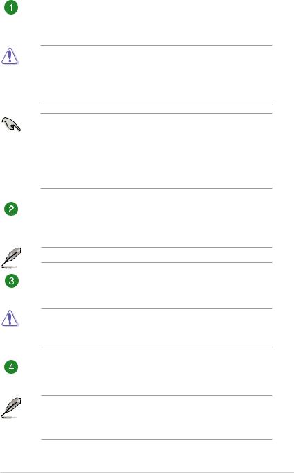
DANGER/WARNING: Information to prevent injury to yourself when completing a task.
CAUTION: Information to prevent damage to the components when completing a task
IMPORTANT: Instructions that you MUST follow to complete a task.
NOTE: Tips and additional information to help you complete a task.
Typography
Bold text |
Indicates a menu or an item to select. |
Italics |
Used to emphasize a word or a phrase. |
<Key> |
Keys enclosed in the less-than and greater-than sign |
|
means that you must press the enclosed key. |
|
Example: <Enter> means that you must press the Enter or |
|
Return key. |
<Key1> + <Key2> + <Key3> |
If you must press two or more keys simultaneously, the key |
|
names are linked with a plus sign (+). |
v

Package contents
Check your motherboard package for the following items.
Motherboard |
ASUS B250 MINING EXPERT motherboard |
|
|
Cables |
2 x Serial ATA 6.0 Gb/s cables |
|
|
Accessories |
1 x I/O Shield |
|
|
Application DVD |
1 x Support DVD |
|
|
Documentation |
User Guide |
|
|
If any of the above items is damaged or missing, contact your retailer.
B250 MINING EXPERT specifications summary
|
LGA1151 socket for Intel® 7th/6th Generation Core™ i7 / i5 / i3, Pentium®, and |
|
|
Celeron® processors |
|
CPU |
Supports Intel® 14nm CPU |
|
Supports Intel® Turbo Boost Technology 2.0* |
||
|
||
|
* The Intel® Turbo Boost Technology 2.0 support depends on the CPU types. |
|
|
** Refer to www.asus.com for Intel® CPU support list. |
|
Chipset |
Intel® B250 Chipset |
|
|
2 x DIMMs, maximum 32GB, DDR4 2400*/2133**MHz, non-ECC, un-buffered |
|
|
memory*** |
|
|
Dual-channel memory architecture |
|
Memory |
Supports Intel® Extreme Memory Profile (XMP) |
|
* Due to Intel® chipset limitation, DDR4 2400MHz memory frequency is only supported |
||
|
by 7th Generation Intel® processors. Higher memory modules will run at the maximum |
|
|
transfer rate of DDR4 2400MHz. |
|
|
** Due to Intel® chipset limitation, DDR4 2133MHz and higher memory modules on 6th |
|
|
Generation Intel® processors will run at the maximum transfer rate of DDR4 2133MHz. |
|
|
*** Refer to www.asus.com for the Memory QVL(Qualified Vendors List) |
|
Expansion |
1 x PCI Express x16 slot (at x16 mode) |
|
slots |
18 x PCI Express x1 slots |
|
|
|
|
|
Integrated graphics processor - Intel® HD Graphics support |
|
Graphics |
- Supports HDMI with maximum resolution of 4096 x 2160 @ 24Hz / 2560 x |
|
1600 @ 60Hz |
||
|
||
|
Maximum shared memory of 1024 MB |
|
Storage |
Intel® B250 Chipset: |
|
- 4 x SATA 6.0 Gb/s ports (gray) |
||
|
||
LAN |
Intel® I219V Gigabit LAN |
|
|
Intel® B250 Chipset |
|
USB |
- 6 x USB 3.1 Gen 1 ports (2 ports at mid-board; 4 ports at back panel, blue, |
|
Type A) |
||
|
||
|
- 4 x USB 2.0/1.1 ports (2 ports at mid-board; 2 ports at back panel) |
|
|
(continued on the next page) |
vi

B250 MINING EXPERT specifications summary
Audio |
Realtek® ALC887 8-channel* High Definition Audio CODEC |
|
* Use a chassis with HD audio module in the front panel to support an 8-channel audio |
||
|
output. |
|
|
ASUS 5X PROTECTION III |
|
|
- ASUS SafeSlot Core: Fortified PCIe Slot prevents damage |
|
ASUS special |
- ASUS LANGuard: Protects against LAN surges, lightning strikes and static- |
|
electricity discharges |
||
features |
||
- ASUS Overvoltage Protection: World-class circuit-protecting power design |
||
|
||
|
- ASUS Stainless Steel Back I/O: 3X corrosion-resistance for greater durability |
|
|
- ASUS DIGI+ VRM: 6 Phase digital power design |
|
|
1 x PS/2 keyboard port |
|
|
1 x PS/2 mouse port |
|
|
1 x HDMI port |
|
Rear panel I/O |
1 x LAN (RJ-45) port |
|
4 x USB 3.1 Gen 1 ports |
||
ports |
||
|
2 x USB 2.0/1.1 ports |
|
|
3 x Audio jacks support 8-channel audio output |
|
|
* Use a chassis with HD audio module in the front panel to support an 8-channel audio |
|
|
output. |
|
|
1 x USB 3.1 Gen 1 connector supports additional 2 USB 3.1 Gen 1 ports (19-pin) |
|
|
1 x USB 2.0/1.1 connector supports additional 2 USB 2.0/1.1 ports |
|
|
4 x SATA 6.0Gb/s connectors |
|
|
1 x CPU Fan connector |
|
|
1 x Chassis Fan connector |
|
Internal |
1 x Front panel audio connector(AAFP) |
|
1 x System panel connector |
||
connectors |
||
1 x S/PDIF out header |
||
|
||
|
3 x 24-pin EATX power connectors |
|
|
3 x 4-pin AUXPWR connectors |
|
|
1 x 8-pin EATX 12V power connector |
|
|
1 x COM header |
|
|
1 x Clear CMOS header |
|
|
64 Mb Flash ROM, UEFI AMI BIOS, PnP, DMI3.0, WfM2.0, SM BIOS 3.0, ACPI |
|
BIOS |
6.0, ASUS EZ Flash 3, F6 Qfan Control, F3 My Favorites, Last Modified log, |
|
F12 PrintScreen, and ASUS DRAM SPD (Serial Presence Detect) memory |
||
|
||
|
information |
|
Manageability |
WfM 2.0, DMI 3.0, WOL by PME, PXE |
|
|
Windows® 10 (64-bit) |
|
OS Support |
Windows® 7 (64-bit)* |
|
|
* Windows® 7 64-bit is only supported when using 6th Generation Intel® processors. |
|
Form Factor |
ATX form factor: 12.0 in x 9.1 in (30.5 cm x 23.1 cm) |
Specifications are subject to change without notice.
vii

Product introduction |
1 |
Motherboard overview |
• Unplug the power cord from the wall socket before touching any component.
•Before handling components, use a grounded wrist strap or touch a safely grounded object or a metal object, such as the power supply case, to avoid damaging them due to static electricity.
•Before you install or remove any component, ensure that the ATX power supply is switched off or the power cord is detached from the power supply. Failure to do so may cause severe damage to the motherboard, peripherals, or components.
•Unplug the power cord before installing or removing the motherboard. Failure to do so can cause you physical injury and damage to motherboard components.
|
|
|
1 |
|
2 |
23.1cm(9.1in) |
3 |
4 |
5 |
|
|
|
|
|
|
|
|
|
|
|
|
|
|
|
|
|
|
|
|
CPU_FAN |
|
|
|
|
|
|
|
|
EATX12V |
|
|
DIGI+ |
|
|
|
|
|
|
|
|
|
|
EPU |
CHA_FAN |
|
|
|
|
|
|
|
|
|
|
|
|
|
|
|
|
|
|
|
Lithium Cell |
|
|
|
|
|
|
|
|
|
|
|
CMOS Power |
|
|
|
|
|
|
|
|
|
|
KBMS |
|
|
|
|
|
|
|
|
|
|
|
USB78 |
|
|
|
|
|
module) |
module) |
® |
|
|
|
|
|
|
|
|
|
pin |
pin |
|
|
|
Place this |
HDMI |
|
|
|
|
LGA1151 |
(64bit,288- |
(64bit,288- |
|
EATXPWR A |
|
side towards |
|
|
|
|
|
|
A1 |
B1 |
|
|
|
the rear of the |
U31G1_56 |
|
LANGuard |
|
|
|
DDR4DIMM |
DDR4DIMM |
|
|
30.5cm(12.0in) |
chassis |
|
|
|
|
|
|
|
||||
|
|
Intel |
|
|
|
|
|
|
|
|
|
|
|
|
I219V |
|
|
|
|
|
|
|
|
|
LAN_U31G1_34 |
|
|
|
|
|
|
|
|
|
|
|
AUDIO |
|
|
|
|
|
|
|
U31G1_12 |
|
|
|
|
|
|
|
|
|
|
|
|
|
|
|
|
|
A01 |
|
A02 |
A03 |
|
|
|
B |
|
|
14 |
|
|
|
|
|
EATXPWR |
1 |
|||
|
|
|
|
|
|
|
|
|
|||
|
|
|
|
|
|
|
|
|
|
|
|
|
13 |
AUXPWR_A1 |
|
PCIEX16_A1 |
|
|
|
|
|
|
|
|
|
|
|
|
|
|
|
|
|||
|
|
|
A04 |
|
A05 |
A06 |
|
|
|
|
|
|
|
Super |
|
|
|
|
|
|
|
|
|
|
|
I/O |
|
|
|
|
|
|
|
|
|
|
|
|
B07 |
|
B08 |
B09 |
|
Intel® |
|
|
|
|
|
AUXPWR_A2 |
|
|
|
|
B250 |
|
|
|
|
|
1 |
|
|
|
|
ASM |
|
|
|
|
|
|
|
|
|
|
1167 |
|
|
|
|
|
|
|
|
|
B10 |
|
B11 |
B12 |
|
|
|
C |
|
|
|
|
|
|
|
|
|
|
64Mb |
EATXPWR |
|
|
ALC |
|
C13 |
|
C14 |
C15 |
|
|
|
|
|
|
|
|
|
|
BIOS |
|
|
||||
|
887 |
AUXPWR_A3 |
|
|
|
|
|
|
|
|
|
|
|
|
|
|
|
|
|
SATA6G_3 |
SATA6G_4 |
|
|
|
|
|
C16 |
|
C17 |
C18 |
|
|
|
|
|
|
|
|
|
|
|
|
USB910 |
|
CLRTC |
|
6 |
|
|
|
SPDIF_OUT |
COM |
|
|
SATA6G_2 |
SATA6G_1 |
PANEL |
||
|
|
|
|
|
|
|
|
|
|
|
|
|
AAFP |
|
|
|
|
|
|
|
|
|
|
|
|
12 |
11 |
10 |
|
|
9 |
|
8 |
7 |
|
Scan the QR code to get the detailed pin definitions.
|
|
|
|
|
|
|
|
|
|
|
|
|
|
|
|
|
|
|
|
|
|
|
|
|
|
|
|
|
|
|
|
|
|
|
|
|
|
|
|
|
|
|
|
|
|
1-1 |
|
ASUS B250 MINING EXPERT |
||||||||||||||||||||
ATX power connectors (24-pin EATXPWR_A/B/C, 8-pin EATX12V, 4-pin AUXPWR_A1/A2/A3)
Correctly orient the ATX power supply plugs into these connectors and push down firmly until the connectors completely fit.
•In order to fully support 19 graphic cards mining, we recommend that you use 3
power supply units (PSU) that are designed for mining with sufficient 12V power plugs and provide a minimum power of 3750W in total (2*1250W + 1*1350W are recommended).
•AUXPWR_A1/A2/A3 must be connected to the same power supply plugged in the 24-pin EATXPWR_A connector.
•We recommend that you use a PSU with higher power output when configuring a
system with more power-consuming devices or when you intend to install additional devices. The system may become unstable or may not boot up if the power is inadequate.
•If you are uncertain about the minimum power supply requirement for your system, refer to the Recommended Power Supply Wattage Calculator at http://support. asus.com/PowerSupplyCalculator/PSCalculator.aspx?SLanguage=en-us for details.
Intel® LGA1151 CPU socket
Install Intel® LGA1151 CPU into this surface mount LGA1151 socket, which is designed for 7th/6th Generation Intel® Core™ i7 / i5 / i3, Pentium®, and Celeron® processors.
For more details, refer to Central Processing Unit (CPU).
CPU and chassis fan connectors (4-pin CPU_FAN, 4-pin CHA_FAN)
Connect the fan cables to the fan connectors on the motherboard, ensuring that the black wire of each cable matches the ground pin of the connector.
Do not forget to connect the fan cables to the fan connectors. Insufficient air flow inside the system may damage the motherboard components. These are not jumpers! Do not place jumper caps on the fan connectors! The CPU_FAN connector supports a CPU fan of maximum 1A (12 W) fan power.
DDR4 DIMM slots
Install 2 GB, 4 GB, 8 GB, and 16 GB unbuffered non-ECC DDR4 DIMMs into these DIMM sockets.
• To make your build more stable, when using 8 or more cards for mining, we recommend that you install 4GB memory modules and change the size of the virtual memory paging file to 30GB.
•For more details, refer to System memory.
Chapter 1: Product introduction |
1-2 |
Loading...