


AP1720-E2
Dual Intel® Xeon™ 5U Rackmount Server
800/533MHz Front Side Bus
User Guide

E1733
First Edition V1
October 2004
Copyright © 2004 ASUSTeK COMPUTER INC. All Rights Reserved.
No part of this manual, including the products and software described in it, may be reproduced, transmitted, transcribed, stored in a retrieval system, or translated into any language in any form or by any means, except documentation kept by the purchaser for backup purposes, without the express written permission of ASUSTeK COMPUTER INC. (“ASUS”).
ASUS provides this manual “as is” without warranty of any kind, either express or implied, including but not limited to the implied warranties or conditions of merchantability or fitness for a particular purpose. In no event shall ASUS, its directors, officers, employees, or agents be liable for any indirect, special, incidental, or consequential damages (including damages for loss of profits, loss of business, loss of use or data, interruption of business and the like), even if ASUS has been advised of the possibility of such damages arising from any defect or error in this manual or product.
Specifications and information contained in this manual ae furnished for informational use only, and are subject to change at any time without notice, and should not be construed as a commitment by ASUS. ASUS assumes no responsibility or liability for any errors or inaccuracies that may appear in this manual, including the products and software described in it.
Product warranty or service will not be extended if: (1) the product is repaired, modified or altered, unless such repair, modification of alteration is authorized in writing by ASUS; or (2) the serial number of the product is defaced or missing.
Products and corporate names appearing in this manual may or may not be registered trademarks or copyrights of their respective companies, and are used only for identification or explanation and to the owners’ benefit, without intent to infringe.
ii

Contents
Notices ............................................................................................ |
v |
Safety information .......................................................................... |
vi |
About this guide ............................................................................. |
vii |
Chapter |
1: Product introduction |
|
|
1.1 |
System package contents .................................................. |
1-2 |
|
1.2 |
System specifications ......................................................... |
1-3 |
|
1.3 |
Front panel features ........................................................... |
1-4 |
|
1.4 |
Rear panel features ............................................................ |
1-6 |
|
1.5 |
Internal features ................................................................. |
1-7 |
|
1.6 |
LED information................................................................ |
1-10 |
|
Chapter 2: Hardware setup |
|
||
2.1 |
Chassis cover ..................................................................... |
2-2 |
|
|
2.1.1 Removing the side cover ....................................... |
2-2 |
|
|
2.1.2 Re-installing the side cover .................................... |
2-3 |
|
2.2 |
Motherboard information .................................................... |
2-4 |
|
2.3 |
Central Processing Unit (CPU)........................................... |
2-5 |
|
|
2.3.1 |
Overview ................................................................ |
2-5 |
|
2.3.2 |
Installing the CPU .................................................. |
2-5 |
|
2.3.3 Installing the CPU heatsink and fan ....................... |
2-7 |
|
2.4 |
System memory ............................................................... |
2-10 |
|
|
2.4.1 |
Overview .............................................................. |
2-10 |
|
2.4.2 |
Memory configurations ........................................ |
2-10 |
|
2.4.2 |
Installing a DIMM ................................................. |
2-12 |
|
2.4.3 |
Removing a DIMM ............................................... |
2-12 |
2.5 |
Front panel assembly ....................................................... |
2-13 |
|
|
2.5.1 Removing the front panel assembly .................... |
2-13 |
|
|
2.5.2 Re-installing the front panel assembly ................. |
2-15 |
|
2.6 |
5.25-inch drives ................................................................ |
2-16 |
|
2.7 |
Hard disk drives................................................................ |
2-19 |
|
|
2.7.1 Installing a hot-swap SATA/SCSI hard disk drive .... |
2-19 |
|
|
2.7.2 Installing an internal IDE/SATA HDD ................... |
2-21 |
|
2.8 |
Expansion cards ............................................................... |
2-26 |
|
|
2.8.1 Installing a standard size expansion card ............ |
2-26 |
|
|
2.8.2 Installing a long expansion card .......................... |
2-28 |
|
|
2.8.3 Removing an expansion card .............................. |
2-29 |
|
iii

Contents
2.9 |
Cable connections ............................................................ |
2-30 |
|
|
2.9.1 |
Motherboard connections .................................... |
2-30 |
|
2.9.2 |
SATA backplane connections............................... |
2-31 |
|
2.9.3 |
SCSI backplane connections ............................... |
2-34 |
2.10 |
Removable components................................................... |
2-39 |
|
|
2.10.1 |
Chassis fan .......................................................... |
2-39 |
|
2.10.2 |
HDD fan ............................................................... |
2-41 |
|
2.10.3 |
SATA/SCSI backplane ......................................... |
2-44 |
|
2.10.4 |
Floppy disk drive .................................................. |
2-46 |
|
2.10.5 |
Front I/O board .................................................... |
2-48 |
|
2.10.6 |
Chassis footpads and roller wheels ..................... |
2-50 |
|
2.10.7 |
Power suppy modules ......................................... |
2-52 |
Chapter 3: Installation options |
|
||
3.1 |
Installing a second SCSI drive cage................................... |
3-2 |
|
3.2 |
Installing an IDE drive cage................................................ |
3-5 |
|
3.3 |
Upgrading to a dual or redundant power supply ................ |
3-7 |
|
3.4 |
Installing a power supply module ....................................... |
3-9 |
|
3.5 |
Mounting the system to a rack .......................................... |
3-11 |
|
|
3.5.1 |
Remove the footpads or roller wheels .................. |
3-11 |
|
3.5.2 |
Remove the top cover ........................................... |
3-11 |
|
3.5.3 |
Attach the rack rails .............................................. |
3-11 |
Chapter 4: Motherboard info |
|
||
4.1 |
Motherboard layout ............................................................ |
4-2 |
|
4.2 |
Jumpers.............................................................................. |
4-4 |
|
4.3 |
Connectors ......................................................................... |
4-8 |
|
Chapter 5: BIOS setup |
|
||
5.1 |
Managing and updating your BIOS .................................... |
5-2 |
|
|
5.1.1 |
Creating a bootable floppy disk ............................. |
5-2 |
|
5.1.2 |
AwardBIOS Flash Utility ........................................ |
5-3 |
|
5.1.3 |
ASUS EZ Flash Utility ............................................ |
5-7 |
5.2 |
BIOS Setup program .......................................................... |
5-8 |
|
|
5.2.1 |
BIOS menu screen ................................................ |
5-9 |
|
5.2.2 |
Menu bar ................................................................ |
5-9 |
|
5.2.3 |
Navigation keys ..................................................... |
5-9 |
|
5.2.4 |
General help ........................................................ |
5-10 |
iv

|
5.2.5 |
Sub-menu ............................................................ |
5-10 |
|
5.2.6 |
Scroll bar .............................................................. |
5-10 |
|
5.2.7 |
Pop-up window .................................................... |
5-10 |
5.3 |
Main menu......................................................................... |
5-11 |
|
|
5.3.1 |
Primary IDE Master ............................................. |
5-12 |
|
5.3.2 |
Primary IDE Slave ............................................... |
5-15 |
|
5.3.3 |
Secondary IDE Master ......................................... |
5-15 |
|
5.3.4 |
Secondary IDE Slave ........................................... |
5-15 |
|
5.3.5 |
Third IDE Master .................................................. |
5-16 |
|
5.3.6 |
Fourth IDE Master ............................................... |
5-16 |
5.4 |
Advanced menu ............................................................... |
5-17 |
|
|
5.4.1 |
Advanced BIOS Features .................................... |
5-17 |
|
5.4.2 |
CPU Configuration ............................................... |
5-18 |
|
5.4.3 |
Memory Configuration ......................................... |
5-19 |
|
5.4.4 |
Chipset ................................................................. |
5-20 |
|
5.4.5 |
Onboard Device ................................................... |
5-23 |
|
5.4.6 |
PCIPnP ................................................................ |
5-28 |
|
5.4.7 |
USB Configuration ............................................... |
5-30 |
5.5 |
Power menu ..................................................................... |
5-31 |
|
|
5.5.1 |
APM Configuration ............................................... |
5-32 |
|
5.5.2 |
Hardware Monitor ................................................ |
5-35 |
5.6 |
Boot menu ........................................................................ |
5-37 |
|
|
5.6.1 |
Boot Device Priority ............................................. |
5-37 |
|
5.6.2 Hard Disk Boot Priority ........................................ |
5-38 |
|
|
5.6.3 |
Removable Device Priority .................................. |
5-38 |
|
5.6.4 |
Boot Settings Configuration ................................. |
5-39 |
|
5.6.5 |
Security ................................................................ |
5-41 |
5.7 |
Exit menu ......................................................................... |
5-43 |
|
Appendix: Reference information
A.1 |
600 W single power supply ................................................ |
A-2 |
|
|
A.1.1 |
General description ................................................ |
A-2 |
|
A.1.2 |
Specifications ......................................................... |
A-3 |
A.2 |
600 W dual/redundant power supply .................................. |
A-4 |
|
|
A.2.1 |
General description ................................................ |
A-4 |
|
A.2.2 |
Specifications ......................................................... |
A-5 |
A.3 |
Simple fixes ........................................................................ |
A-6 |
|
v
Notices
Federal Communications Commission Statement
This device complies with Part 15 of the FCC Rules. Operation is subject to the following two conditions:
•This device may not cause harmful interference, and
•This device must accept any interference received including interference that may cause undesired operation.
This equipment has been tested and found to comply with the limits for a Class B digital device, pursuant to Part 15 of the FCC Rules. These limits are designed to provide reasonable protection against harmful interference in a residential installation. This equipment generates, uses and can radiate radio frequency energy and, if not installed and used in accordance with manufacturer’s instructions, may cause harmful interference to radio communications. However, there is no guarantee that interference will not occur in a particular installation. If this equipment does cause harmful interference to radio or television reception, which can be determined by turning the equipment off and on, the user is encouraged to try to correct the interference by one or more of the following measures:
•Reorient or relocate the receiving antenna.
•Increase the separation between the equipment and receiver.
•Connect the equipment to an outlet on a circuit different from that to which the receiver is connected.
•Consult the dealer or an experienced radio/TV technician for help.
WARNING! The use of shielded cables for connection of the monitor to the graphics card is required to assure compliance with FCC regulations. Changes or modifications to this unit not expressly approved by the party responsible for compliance could void the user’s authority to operate this equipment.
Canadian Department of Communications Statement
This digital apparatus does not exceed the Class B limits for radio noise emissions from digital apparatus set out in the Radio Interference Regulations of the Canadian Department of Communications.
This class B digital apparatus complies with Canadian ICES-003.
vi
Safety information
Electrical Safety
•Before installing or removing signal cables, ensure that the power cables for the system unit and all attached devices are unplugged.
•To prevent electrical shock hazard, disconnect the power cable from the electrical outlet before relocating the system.
•When adding or removing any additional devices to or from the system, ensure that the power cables for the devices are unplugged before the signal cables are connected. If possible, disconnect all power cables from the existing system before you add a device.
•If the power supply is broken, do not try to fix it by yourself. Contact a qualified service technician or your dealer.
Operation Safety
•Any mechanical operation on this server must be conducted by certified or experienced engineers.
•Before operating the server, carefully read all the manuals included with the server package.
•Before using the server, make sure all cables are correctly connected and the power cables are not damaged. If any damage is detected, contact your dealer as soon as possible.
•To avoid short circuits, keep paper clips, screws, and staples away from connectors, slots, sockets and circuitry.
•Avoid dust, humidity, and temperature extremes. Place the server on a stable surface.
This product is equipped with a three-wire power cable and plug for the user’s safety. Use the power cable with a properly grounded electrical outlet to avoid electrical shock.
 Lithium-Ion Battery Warning
CAUTION! Danger of explosion if battery is incorrectly replaced. Replace only with the same or equivalent type recommended by the manufacturer. Dispose of used batteries according to the manufacturer’s instructions.
 CD-ROM Drive Safety Warning
CLASS 1 LASER PRODUCT
Heavy System
CAUTION! This server system is heavy. Ask for assistance when moving or carrying the system.
vii

About this guide
Audience
This user guide is intended for system integrators, and experienced users with at least basic knowledge of configuring a server.
Contents
This guide contains the following parts:
1.Chapter 1: Product Introduction
This chapter describes the general features of the AP130-E1 server. It includes sections on front panel and rear panel specifications.
2.Chapter 2: Hardware setup
This chapter lists the hardware setup procedures that you have to perform when installing or removing system components.
3.Chapter 3: Installation options
This chapter describes how to install optional components into the barebone server.
4.Chapter 4: Motherboard information
This chapter includes the motherboard layout and brief descriptions of the jumpers and internal connectors.
5.Chapter 5: BIOS setup
This chapter tells how to change the system settings through the BIOS Setup menus. Detailed descriptions of the BIOS parameters are also provided.
6.Appendix: Reference information
This appendix gives information on the standard or redundant power supply that came with the barebone server. This section also provides a troubleshooting guide for solving common problems when using the barebone server.
viii
Conventions
To make sure that you perform certain tasks properly, take note of the following symbols used throughout this manual.
WARNING: Information to prevent injury to yourself when trying to complete a task.
CAUTION: Information to prevent damage to the components when trying to complete a task.
IMPORTANT: Information that you MUST follow to complete a task.
NOTE: Tips and information to aid in completing a task.
Reference
Visit the ASUS websites worldwide that provide updated information for all ASUS hardware and software products. Refer to the ASUS contact information for details.
ix

x
Chapter 1
This chapter describes the general features of the barebone server. It includes sections on the front panel and rear panel specifications.
ASUS AP1720-E2 user guide
Product introduction
1-1
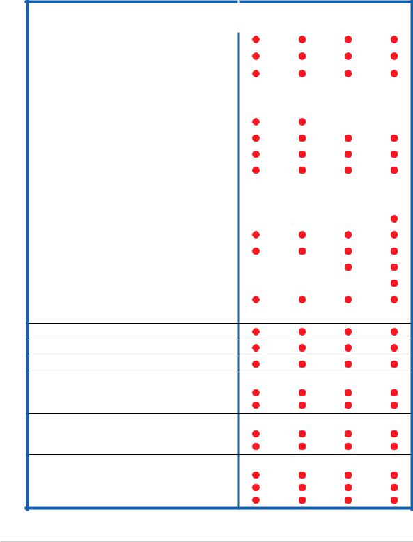
1.1System package contents
Check your ASUS AP1720-E2 package with the items on the following table. The package contents vary for the following configurations:
•AS8 (eight hot-swap SCSI hard disk drives)
•AS4 (four hot-swap SCSI hard disk drives)
•AA4 (four hot-swap SATA hard disk drives)
•AI4 (four internal SATA/IDE hard disk drives)
|
Item Description |
|
Configurations |
|
|
|
AS8 |
AS4 |
AA4 |
AI4 |
|
|
|
||||
|
|
|
|
|
|
ASUS AK25 5U rackmount chassis with: |
|
|
|
|
|
|
|
|
|
|
|
• ASUS NCCH-DL motherboard |
|
|
|
|
|
• |
600 W single or redundant power supply* |
|
|
|
|
|
|
|
|
|
|
• |
SATA backplane board |
|
|
1 |
|
|
|
|
|
|
|
• |
SCSI backplane board |
2 |
1 |
|
|
|
|
|
|
|
|
• |
ASUS U320 SCSI card and cable |
|
|
|
|
|
|
|
|
|
|
• |
52x CD-ROM drive |
|
|
|
|
|
|
|
|
|
|
• |
Floppy disk drive |
|
|
|
|
|
|
|
|
|
|
• |
Chassis fan |
|
|
|
|
|
|
|
|
|
|
• |
HDD fan |
2 |
1 |
1 |
|
|
|
|
|
|
|
• |
Hot-swap HDD trays (including HDD screws) |
8 |
4 |
4 |
|
|
|
|
|
|
|
• |
Internal HDD rails (4 pairs) |
|
|
|
|
|
|
|
|
|
|
• |
Chassis roller wheels (1 set) |
|
|
|
|
|
|
|
|
|
|
• |
Front I/O board |
|
|
|
|
|
|
|
|
|
|
• SATA signal cable (4 sets) |
|
|
|
|
|
|
|
|
|
|
|
• |
SATA power cable |
|
|
|
|
|
|
|
|
|
|
• |
SMBus cable |
|
|
|
|
|
|
|
|
|
|
• |
Dummy covers (4 pieces) |
|
4 |
4 |
8 |
AC power cable
System screws and cables
System keys ( 2 pcs.)
Bundled CDs
• AP1720-E2 support CD with ASWM**
• TrendMicro® ServerProtect® CD
Documentation
• ASUS AP1720-E2 user guide
• ASUS NCCH-DL user guide
Optional items
• ASUS AK25 rackmount rail kit
• ASUS AK25 internal HDD cage (non-hot swap)
• ASUSAK25 600 W 2+1 redundant power supply
*All models support a 600 W single or redundant power supply.
**ASUS System Web-based Management
1-2 |
Chapter 1: Product introduction |

1.2System specifications
The ASUS AP1720-E2 is a barebone server system featuring the ASUS NCCH-DL motherboard. The server supports dual Intel® Xeon™ processors in 604-pin sockets, and includes the latest technologies through the chipsets embedded on the motherboard.
Chassis |
Pedestal or rackmount 5U with removable front door bezel and |
|
chassis foot stand or roller-wheels. |
|
|
System dimension |
431 mm (H) x 220 mm (W) x 510 mm (D) |
|
|
Motherboard |
ASUS NCCH-DL (ATX form factor: 12 in x 9.8 in)* |
|
|
Chipset |
Intel® E82875P Memory Controller Hub (MCH) |
|
Intel® 6300ESB I/O Controller Hub (ICH) |
Processor |
Socket 604 for Intel® Xeon™ Nocona/Prestonia CPU with |
|
800/533MHz FSB and on-die 1MB/512KB L2 cache with full speed |
|
|
Memory |
4 x 184-pin DDR sockets for up to 4GB memory |
|
Supports PC3200/2700/2100 unbuffered ECC or |
|
non-ECC DDR DIMMs |
|
|
LAN |
Intel® 82547GI Gigabit LAN controller(CSA) |
RAID |
Promise® PDC20319 controller |
|
(supports RAID 0/RAID 1/RAID 0+1/Multi-RAID) |
|
|
Expansion slots |
1 x AGP Pro/8X slot |
|
2 x 64-bit/66Mhz 3.3V PCI-X slots** |
|
2 x 32-bit/33Mhz 5V PCI slots |
|
|
Drive bays |
1 x 3.25-inch FDD bay |
|
3 x 5.25-inch drive bays |
|
|
Front I/O |
1 x IEEE 1394 port |
|
1 x Headphone port |
|
1 x Microphone port |
|
|
Rear panel I/O |
1 x Parallel port |
|
2 x Serial ports |
|
1 x LAN (RJ-45) port |
|
4 x USB 2.0 ports |
|
1 x IEEE 1394 port |
|
1 x PS/2 keyboard port |
|
1 x PS/2 mouse port |
|
Line In / Line Out / Microphone ports |
|
|
Management |
ASUS Server Web-based Management (ASWM) 2.0 |
|
|
Hardware monitors |
Voltage, temperature, and fan speed monitoring |
|
Automatic System Restart (ASR) feature |
|
|
Power supply |
600 W power supply (with 24-pin and 8-pin power plugs) or |
|
600 W redundant power supply (optional) |
|
|
*Refer to Chapter 4 “Motherboard information” for information on the internal connectors.
**In AS8/AS4 models, the ASUS U160/U320 SCSI card occupies one 64-bit PCI-X slot.
ASUS AP1720-E2 barebone server |
1-3 |
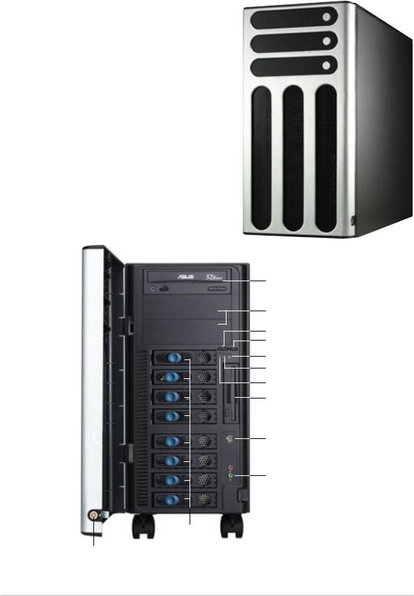
1.3Front panel features
The AP1720-E2 chassis displays a stylish front bezel with lock. The bezel covers the system components on the front panel and serves as security. Open the bezel to access the front panel components.
The drive bays, power and reset buttons, LED indicators, CD-ROM drive, floppy drive, IEEE 1394 and front panel audio ports are located on the front panel. For future installation of 5.25-inch devices, two drive bays are available.
CD-ROM drive
Empty 5.25-inch bays
Power button
Reset button
Message LED
HDD access LED
Power LED
Floppy disk drive
IEEE 1394 port

 Microphone port
Headphone port
Drive bays
Security lock
1-4 |
Chapter 1: Product introduction |
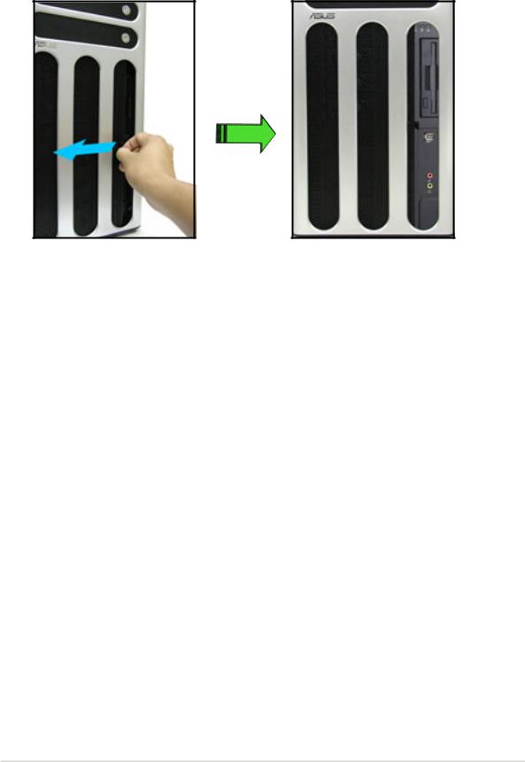
If you wish to access front I/O ports and floppy disk drive without opening the bezel, hold the tab and move the sliding panel (rightmost panel) to the left as shown.
ASUS AP1720-E2 barebone server |
1-5 |
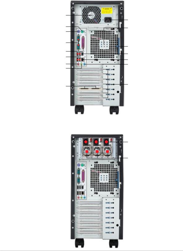
1.4Rear panel features
The rear panel includes a slot for the motherboard rear I/O ports, expansion slots, a chassis lock and intrusion switch, a vent for the system fan, and power supply module.
Single power supply models
Power supply module
PS/2 mouse port PS/2 keyboard port
Serial ports
Parallel port
USB ports
Microphone port
Line Out port
SCSI connectors*
*On AS8/AS4 configuration only.
Power connector 12 cm system fan
Chassis cover lock IEEE 1394 port Gigabit LAN port Line In port
Expansion slots
Redundant power supply models
Power connectors
300 W power supply modules**
**The system comes with two power supply module. The third power supply module for redundant power is optional.
1-6 |
Chapter 1: Product introduction |

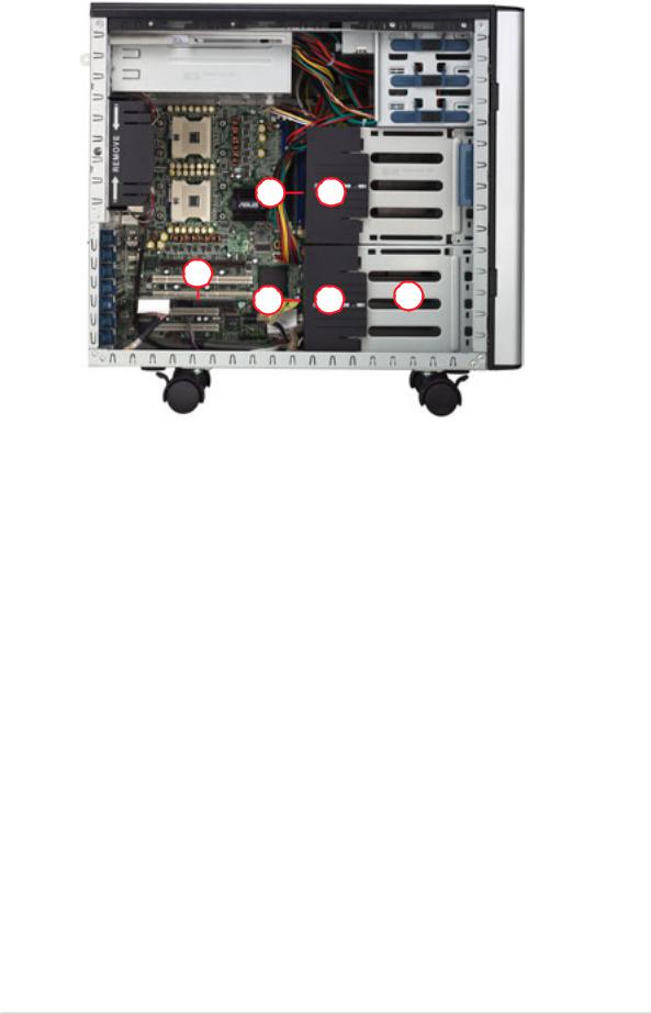
1.5Internal features
The barebone server system includes the basic components as shown.
AI4 (four internal IDE/SATA configuration)
2
|
1 |
|
3 |
|
5 |
|
4 |
10 |
7 |
6 |
9 |
|
|
|
|
8 |
|
|
1. |
Power supply cage |
|
|
||
6. |
Expansion card locks |
||||
2. |
CD-ROM drive |
7. |
NCCH-DL motherboard |
||
3. |
2 x 5.25-inch drive bays |
8. |
Chassis roller wheels |
||
4. |
Hard disk drive cage |
9. |
Front I/O board |
||
5. |
Chassis fan |
10. Chassis intrusion switch |
|||
ASUS AP1720-E2 barebone server |
1-7 |

AA4 (four hot-swap SATA configuration)
2
1
3
5
12 11 4
10 |
7 |
 9 6
9 6 
8
AS4 (four hot-swap SCSI configuration)
13 11
14
1-8 |
Chapter 1: Product introduction |
AS8 (eight hot-swap SCSI configuration)
13 11
14
15 16 17
1. |
Power supply cage |
10. Chassis intrusion switch |
2. |
CD-ROM drive |
11. HDD fan |
3. |
2 x 5.25-inch drive bays |
12. SATA backplane (hidden) |
4. |
Hard disk drive cage |
13. SCSI backplane (hidden) |
5. |
Chassis fan |
14. ASUS U160/U320 SCSI card |
6. |
Expansion card locks |
15. Second SCSI backplane (hidden) |
7. |
NCCH-DL motherboard |
16. Second HDD fan |
8. |
Chassis roller wheels |
17. Second hard disk drive cage |
9. |
Front I/O board |
|
ASUS AP1720-E2 barebone server |
1-9 |
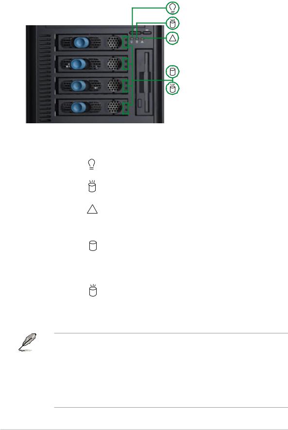
1.6LED information
The barebone system comes with five LED indicators. Refer to the following table for the LED status description.
Power LED (blue)
HDD Access LED (green)
! Message LED (red)
Drive Status LED (green/red)
Drive Activity LED (green)
LED |
Icon |
Display status |
Description |
|
|
|
|
|
|
System |
|
|
|
|
|
|
|
|
|
Power LED |
|
ON |
System power ON |
|
|
|
Blinking |
System is in suspend mode |
|
HDD Access LED |
|
OFF |
No activity |
|
|
|
Blinking |
Read/write data into the HDD |
|
Message LED |
! |
OFF |
System is normal; no incoming event |
|
|
|
Blinking |
ASMS indicates a HW monitor event |
|
|
|
|
|
|
Hard disk drives |
|
|
|
|
|
|
|
|
|
Drive Status LED |
|
Green |
Installed HDD is in good condition |
|
|
|
Red |
HDD failure |
|
|
|
Red and Green |
HDD rebuilding using the RAID card |
|
|
|
blinking alternately* |
SAF-TE** function |
|
Drive Activity LED |
|
Blinking |
Read/write data into the HDD |
|
|
|
|
|
|
*For SCSI models only (AS8/AS4)
**SCSI Access Fault-Tolerant Enclosure (on AS8/AS4 models only)
• The Power, HDD Access, and Message LEDs are visible even if the system front bezel is closed.
•For AA4 configuration:
1.The Drive Activity LEDs do not light up
2.The Drive Status LEDs only light up green to indicate that the installed Serial ATA HDD is in good condition.
1-10 |
Chapter 1: Product introduction |
Chapter 2
This chapter lists the hardware setup procedures that you have to perform when installing or removing system components.
Hardware setup
ASUS AP1720-E2 barebone server |
2-1 |
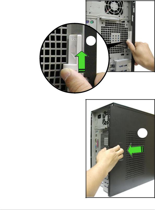
2.1Chassis cover
The chassis features a “screwless design” that allows convenient assembly and disassembly. You can simply push or slide mechanical bolts and locks to remove the cover.
2.1.1 Removing the side cover
1.Push up the chassis lock on the rear panel to release the side cover.
1
2.Slide the side cover for about half an inch toward the rear until it is disengaged from the chassis.
2
2-2 |
Chapter 2: Hardware setup |
Viewing the internal structure
Without the side cover, the internal structure and installed components of the barebone server vary depending on the model you purchased. Refer to section “1.5 Internal features” for the different model configurations.
Perform the procedures in the succeeding sections to install the CPU, system memory, disk drives, and expansion cards; replace fans and power supply; and connect the system cables.
You may need to remove some of the installed components to access the DIMM sockets and internal connectors. Refer to section “2.10 Removable components” for instructions.
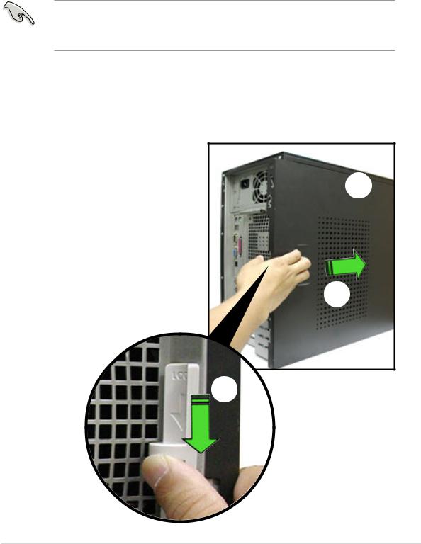
2.1.2 Re-installing the side cover
To re-install the side cover:
1.Match and insert the hooks of the cover to the elongated holes on the side of the chassis. All the six hooks (three each on the top and bottom) of the cover must properly fit the designated holes.
2.Slide the cover toward the front until it snaps in place.
3.Push down the chassis lock to secure the side cover.
1
2
3
ASUS AP1720-E2 barebone server |
2-3 |
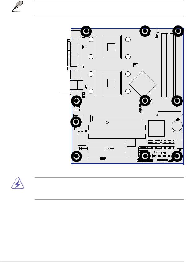
2.2Motherboard information
The barebone server comes with the ASUS NCCH-DL motherboard already installed. The motherboard is secured to the chassis by ten (10) screws as indicated by circles in the illustration below.
Refer to “Chapter 4 Motherboard information” for detailed information on the motherboard.
This side towards
the rear of the chassis
-DL |
® |
NCCH |
|
Make sure to unplug the power cord before installing or removing any motherboard component or connection. Failure to do so may cause you physical injury and may damage motherboard components.
2-4 |
Chapter 2: Hardware setup |
2.3Central Processing Unit (CPU)
2.3.1 Overview
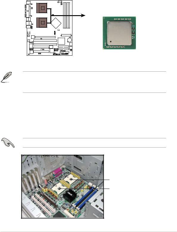
The motherboard comes with dual surface mount 604-pin Zero Insertion Force (ZIF) sockets. The sockets are designed for the Intel® Xeon™ Processor in the 604-pin package.
NCCH-DL |
Intel Xeon
Gold Arrow 
NCCH-DL Socket 604
Before installing the CPU, remove the chassis fan attached to the inner side of the rear panel to allow enough space for the installation. Refer to section “2.10 Removable components” for details.
2.3.2 Installing the CPU
Note in the above illustration that the CPU has a gold triangular mark on one corner. This mark indicates the processor Pin 1 that should match a specific corner of the CPU socket.
If installing only one CPU, use the socket CPU1.
Socket for CPU1
Socket for CPU2
ASUS AP1720-E2 barebone server |
2-5 |
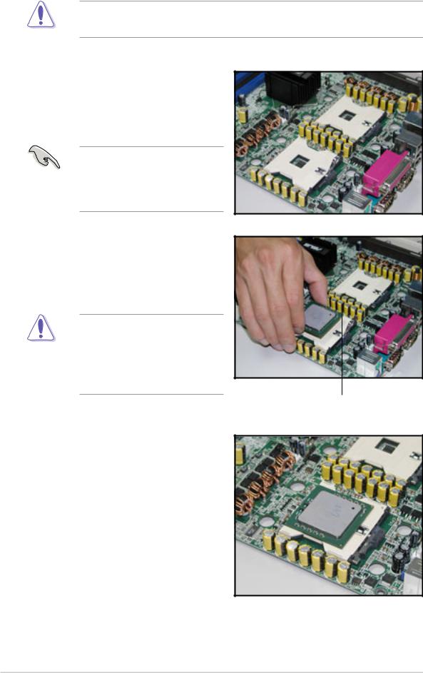
Incorrect installation of the CPU into the socket may bend the pins and severely damage the CPU!
Follow these steps to install a CPU.
1.Locate the 604-pin ZIF sockets on the motherboard. Flip up the socket lever and push it all the way to the other side.
Make sure that the socket lever is pushed back all the way, otherwise the CPU does not fit in completely.
2.Position the CPU above the socket as shown.
3.Carefully insert the CPU into the socket until it fits in place.
The CPU fits only in one correct orientation. DO NOT force the CPU into the socket to prevent bending the pins and damaging the CPU!
Marked corner (gold arrow)
4.Carefully push down the socket lever to secure the CPU. The lever clicks on the side tab to indicate that it is locked.
5.Apply the thermal interface material (thermal grease) to the top of the CPU. This thermal grease should come with the CPU package.
6.Repeat steps 1 to 5 if you wish to install a second CPU.
2-6 |
Chapter 2: Hardware setup |
2.3.3 Installing the CPU heatsink and fan
The Intel® Xeon™ processors require an Intel® certified heatsink and fan assembly to ensure optimum thermal condition and performance.
When you buy a boxed Intel® CPU, the package includes the heatsink, fan, retention brackets, screws, thermal grease, installation manual, and other items that are necessary for CPU and CPU heatsink and fan installation.
Important notes
• This system does not support Intel® Xeon™ FSB 533 box fan and heatsink assembly. When installing Intel® Xeon™ FSB 533 CPU(s), it is recommended that you use Nocona-compatible fan and heatsink assembly. Visit the ASUS website for details and a list of CPU fan and heatsink assembly qualified for use on this system.
•When installing Intel® Xeon™ FSB 800 boxed CPU(s), it is recommended that you use the fan and heatsink assembly (ies) included in the CPU package(s).
•Refer to the installation manual that came with the CPU package for details on fan and heatsink assembly installation.
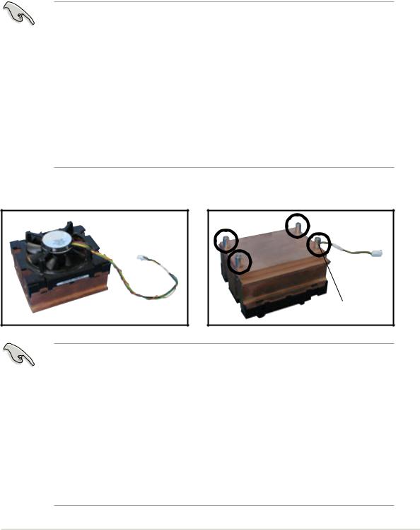
CPU heatsink (top view) |
CPU heatsink (bottom view) |
Heatsink screw
Before installing the CPU heatsinks:
•Make sure that you have applied the thermal grease on top of the CPU before installing the fan and heatsink assembly.
•Ensure that the jumpers FM_CPU1 and FM_CPU2 are set correctly depending on the pin definition of your CPU fan cables. Refer to the motherboard user guide for information.
•Remove the chassis fan to have more space for the CPU fan and heatsink assembly installation. Refer to section “2.10 Removable components” for details.
ASUS AP1720-E2 barebone server |
2-7 |
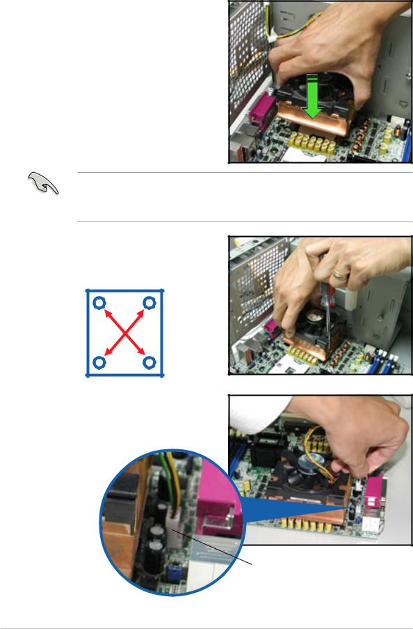
To install the CPU heatsink and fan:
1.Place the heatsink on top of the installed CPU, making sure that the four screws on the heatsink align with the screw holes on the CEK spring.
The CEK springs come pre-installed under the CPU sockets to support the weight of the CPU heatsinks. It is recommended that you keep the springs installed to prevent motherboard breakage.
2.Use a Phillips screwdriver to tighten the four heatsink screws in a diagonal sequence.
42
13
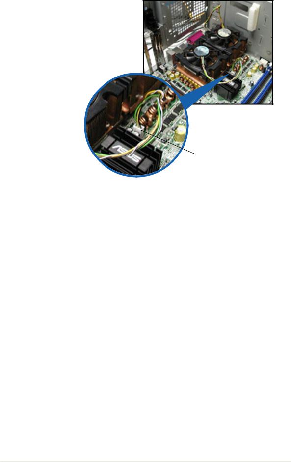
3.Connect the fan cable to the 4-pin connector labeled CPU_FAN1.
CPU1 fan connector (CPU_FAN1)
2-8 |
Chapter 2: Hardware setup |
4.Repeat steps 1 to 3 to install the other heatsink if you have installed a second CPU, then connect the fan cable to the 4-pin connector labeled CPU_FAN2.
The heatsinks appear as shown when installed.
CPU2 fan connector (CPU_FAN2)
ASUS AP1720-E2 barebone server |
2-9 |
2.4System memory
2.4.1 Overview
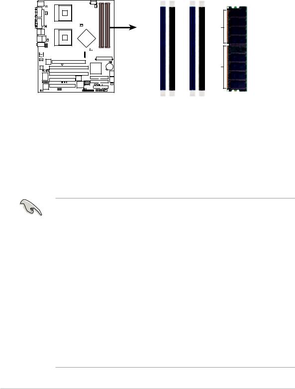
The motherboard comes with four Double Data Rate (DDR) Dual Inline Memory Module (DIMM) sockets.
The following figure illustrates the location of the DDR DIMM sockets.
NCCH-DL |
DIMM A1 |
DIMM A2 |
DIMM B1 |
DIMM B2 |
Pins |
|
|
|
|
80 |
|
|
|
|
104 Pins |
NCCH-DL 184-pin DDR DIMM sockets
2.4.2 Memory configurations
You may install unbuffered ECC or non-ECC 64MB, 128MB, 256MB, 512MB, and 1GB DDR DIMMs into the DIMM sockets using the recommended memory configurations.
Important notes
1.Installing DDR DIMMs other than the recommended configurations may cause memory sizing error or system boot failure. Use any of the recommended configurations in Table 1.
2.In dual-channel configurations, install only identical (the same type and size) DDR DIMM pairs for each channel.
3.Always install DIMMs with the same CAS latency. For optimum compatibility, it is recommended that you obtain memory modules from the same vendor.
4.Make sure that the memory frequency matches the CPU FSB (Front Side Bus). Refer to Table 2.
5.DIMMs installed into any three sockets will function in singlechannel mode.
6.When all four sockets are populated with 1GB DIMMs (total 4GB), the system may detect only about 3.6+ GB (less than 4 GB) due to resource allocation on onboard devices.
2-10 |
Chapter 2: Hardware setup |
 Loading...