


1 E1309

Product Name: Notebook PC Hardware
Manual Revision: 1 E1309
Release Date: May 2003
Notebook PC
Hardware User’s Manual

2
Safety Statements
Federal Communications Commission Statement
This device complies with FCC Rules Part 15. Operation is subject to the following two conditions:
• This device may not cause harmful interference, and
• This device must accept any interference received, including interference that may cause undesired
operation.
This equipment has been tested and found to comply with the limits for a class B digital device, pursuant
to Part 15 of the Federal Communications Commission (FCC) rules. These limits are designed to provide
reasonable protection against harmful interference in a residential installation. This equipment generates,
uses, and can radiate radio frequency energy and, if not installed and used in accordance with the instruc-
tions, may cause harmful interference to radio communications. However, there is no guarantee that inter -
ference will not occur in a particular installation. If this equipment does cause harmful interference to
radio or television reception, which can be determined by turning the equipment off and on, the user is
encouraged to try to correct the interference by one or more of the following measures:
• Reorient or relocate the receiving antenna.
• Increase the separation between the equipment and receiver.
• Connect the equipment into an outlet on a circuit different from that to which the receiver is connected.
• Consult the dealer or an experienced radio/TV technician for help.
Reprinted from the Code of Federal Regulations #47, part 15.193, 1993. Washington DC: Office of the
Federal Register, National Archives and Records Administration, U.S. Government Printing Office.
Power Safety Requirement
Products with electrical current ratings up to 6A and weighing more than 3Kg must use approved power
cords greater than or equal to: H05VV-F, 3G, 0.75mm
2
or H05VV-F, 2G, 0.75mm
2
.
Canadian Department of Communications Statement
This digital apparatus does not exceed the Class B limits for radio noise emissions from digital apparatus
set out in the Radio Interference Regulations of the Canadian Department of Communications.
This Class B digital apparatus complies with Canadian ICES-003.
(Cet appareil numérique de la classe B est conforme à la norme NMB-003 du Canada.)
WARNING! The use of a shielded-type power cord is required in order to meet FCC
emission limits and to prevent interference to the nearby radio and television recep-
tion. It is essential that only the supplied power cord be used. Use only shielded
cables to connect I/O devices to this equipment. You are cautioned that changes or
modifications not expressly approved by the party responsible for compliance could
void your authority to operate the equipment.
3
Safety Statements
Nordic Cautions (for Notebook PC with Lithium-Ion Battery)
(Japanese)
Macrovision Corporation Product Notice
This product incorporates copyright protection technology that is protected by method claims of certain
U.S.A. patents and other intellectual property rights owned by Macrovision Corporation and other rights
owners. Use of this copyright protection technology must be authorized by Macrovision Corporation, and
is intended for home and other limited viewing uses only unless otherwise authorized by Macrovision
Corporation. Reverse engineering or disassembly is prohibited.
CDRH Regulations
The Center for Devices and Radiological Health (CDRH) of the U.S. Food and Drug Administration
implemented regulations for laser products on August 2, 1976. These regulations apply to laser products
manufactured from August 1, 1976. Compliance is mandatory for products marketed in the United States.
A TTENZIONE! Rischio di esplosione della batteria se sostituita in modo errato. Sostituire la batteria con un
una di tipo uguale o equivalente consigliata dalla fabbrica. Non disperdere le batterie nell’ambiente. (Italian)
VORSICHT! Explosionsgetahr bei unsachgemäßen Austausch der Batterie. Ersatz nur durch denselben
oder einem vom Hersteller empfohlenem ähnlichen T yp. Entsorgung gebrauchter Batterien nach Angaben
des Herstellers. (German)
ADVARSELI! Lithiumbatteri - Eksplosionsfare ved fejlagtig håndtering. Udskiftning må kun ske med
batteri af samme fabrikat og type. Levér det brugte batteri tilbage til leverandøren. (Danish)
VARNING! Explosionsfara vid felaktigt batteribyte. Använd samma batterityp eller en ekvivalent typ
som rekommenderas av apparattillverkaren. Kassera använt batteri enligt fabrikantens instruktion. (Swedish)
VAROITUS! Paristo voi räjähtää, jos se on virheellisesti asennettu. V aihda paristo ainoastaan laitevalmistajan
sousittelemaan tyyppiin. Hävitä käytetty paristo valmistagan ohjeiden mukaisesti. (Finnish)
ATTENTION! Il y a danger d’explosion s’il y a remplacement incorrect de la batterie. Remplacer
uniquement avec une batterie du mêre type ou d’un type équivalent recommandé par le constructeur.
Mettre au rebut les batteries usagées conformément aux instructions du fabricant. (French)
ADVARSEL! Eksplosjonsfare ved feilaktig skifte av batteri. Benytt samme batteritype eller en tilsvarende type
anbefalt av apparatfabrikanten. Brukte batterier kasseres i henhold til fabrikantens instruksjoner . (Norwegian)
CAUTION! Danger of explosion if battery is incorrectly replaced. Replace only with the same or
equivalent type recommended by the manufacturer. Dispose of used batteries according to the
manufacturer’s instructions. (English)
WARNING: Use of controls or adjustments or performance of procedures other than
those specified herein or in the laser product installation guide may result in hazard-
ous radiation exposure.
4
Safety Statements
Safety Statements
Disconnect the AC power and remove the battery pack(s) before cleaning. W ipe the Notebook PC using
a clean cellulose sponge or chamois cloth dampened with a solution of nonabrasive detergent and a few
drops of warm water and remove any extra moisture with a dry cloth.
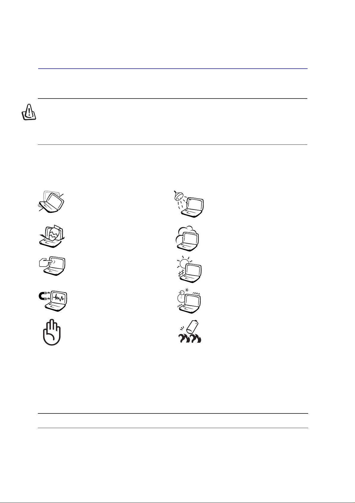
WARNING! The following safety precautions will increase the life of the Notebook PC.
Follow all precautions and instructions. Except as described in this manual, refer all
servicing to qualified personnel. Do not use damaged power cords, accessories, or
other peripherals. Do not use strong solvents such as thinners, benzene, or other
chemicals on or near the surface.
DO NOT expose to or use near liq-
uids, rain, or moisture. DO NOT use
the modem during an electrical storm.
DO NOT expose to dirty or dusty en-
vironments. DO NOT operate during
a gas leak.
DO NOT expose to strong magnetic
or electrical fields.
DO NOT expose to extreme temperatures
above 50˚C (122˚F) or to direct sunlight.
Do not block the fan vents!
DO NOT place on uneven or unstable
work surfaces. Seek servicing if the
casing has been damaged.
DO NOT place or drop objects on top
and do not shove any foreign objects
into the Notebook PC.
DO NOT press or touch the display
panel. Do not place together with small
items that may scratch or enter the Note-
book PC.
DO NOT leave the Notebook PC on
your lap or any part of the body while
the Notebook PC is turned ON or is
charging in order to prevent discom-
fort or injury from heat exposure.
DO NOT throw batteries in fires as
they may explode. Check local codes
for special battery disposal instruc-
tions.
DO NOT expose to extreme tempera-
tures (below 0˚C (32˚F), otherwise the
Notebook PC may not boot.
Temperature range: Safe at ambient temperature up to 40 degrees Celsius.

5
Transportation Precautions
T o prepare the Notebook PC for transport, you should turn it OFF and disconnect all external periph-
erals to prevent damage to the connectors. The hard disk drive’s head retracts when the power is
turned OFF to prevent scratching of the hard disk surface during transport. Therefore, you should not
transport the Notebook PC while the power is still ON. Close the display panel and check that it is
latched securely in the closed position to protect the keyboard and display panel.
Remove Floppy Disks
Make sure your floppy disk drive (external on some models) does not contain a diskette when trans-
porting the floppy disk drive. When a diskette is inserted into the floppy disk drive, the eject button
protrudes out. If you attempt to transport the floppy disk drive with a diskette in the drive, you risk
damaging the eject button and also risk scratching the surface of the diskette when the floppy disk drive
is jolted.
Cover Your Notebook PC
Use a carrying case such as the one supplied with your Notebook PC to protect it from dirt, water,
shock, and scratches.
Safety Statements
Charge Your Batteries
If you intend to use battery power, be sure to fully charge your battery pack and any optional battery
packs before going on long trips. Remember that the power adapter charges the battery pack as long as
it is plugged into the computer and an AC power source. Be aware that it takes much longer to charge
the battery pack when the Notebook PC is in use.
Airplane Precautions
Contact your airline if you want to use the Notebook PC on the airplane. Most airlines will have restric-
tions for using electronic devices. Most airlines will allow electronic use only between and not during
takeoffs and landings.
CAUTION! There are three main types of airport security devices: X-ray machines
(used on items placed on conveyor belts), magnetic detectors (used on people walk-
ing through security checks), and magnetic wands (hand-held devices used on people
or individual items). Y ou can send your Notebook PC and diskettes through airport X-
ray machines. However, it is recommended that you do not send your Notebook PC or
diskettes through airport magnetic detectors or expose them to magnetic wands.
NOTE: The surface glaze is easily dulled if not properly cared for. Be careful not to rub
or scrap the Notebook PC surfaces when transporting your Notebook PC.
6
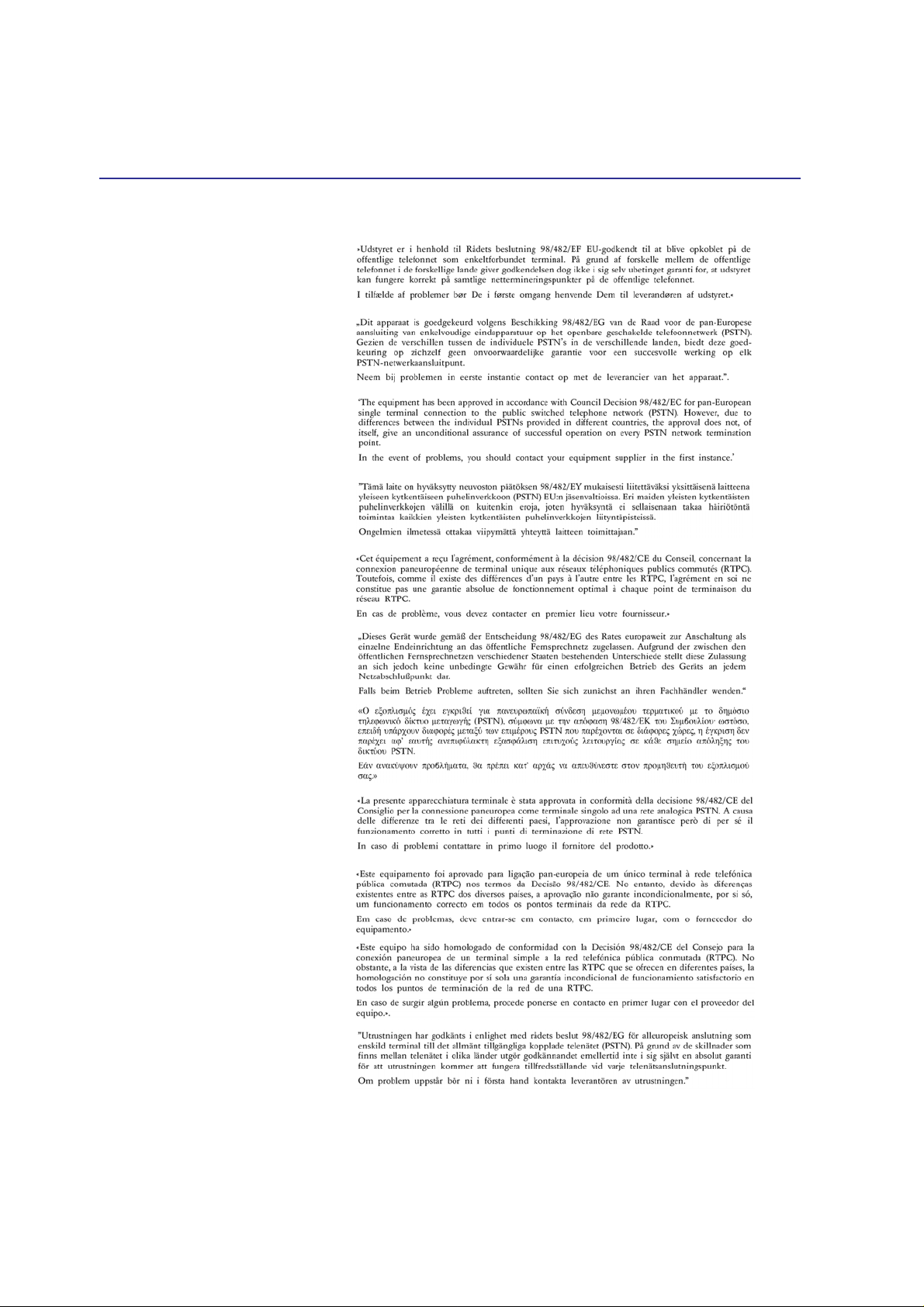
Danish
Dutch
English
Finnish
French
German
Greek
Italian
Portuguese
Spanish
Swedish
CTR 21 Approval (for Notebook PC with built-in Modem)
Safety Statements

7
UL Safety Notices
Required for UL 1459 covering telecommunications (telephone) equipment intended to be electrically
connected to a telecommunication network that has an operating voltage to ground that does not exceed
200V peak, 300V peak-to-peak, and 105V rms, and installed or used in accordance with the National
Electrical Code (NFPA 70).
When using the Notebook PC modem, basic safety precautions should always be followed to reduce
the risk of fire, electric shock, and injury to persons, including the following:
• Do not use the Notebook PC near water, for example, near a bath tub, wash bowl, kitchen sink or
laundry tub, in a wet basement or near a swimming pool.
• Do not use the Notebook PC during an electrical storm. There may be a remote risk of electric shock
from lightning.
• Do not use the Notebook PC in the vicinity of a gas leak.
Required for UL 1642 covering primary (nonrechargeable) and secondary (rechargeable) lithium bat-
teries for use as power sources in products. These batteries contain metallic lithium, or a lithium alloy,
or a lithium ion, and may consist of a single electrochemical cell or two or more cells connected in
series, parallel, or both, that convert chemical energy into electrical energy by an irreversible or revers-
ible chemical reaction.
• Do not dispose the Notebook PC battery pack in a fire, as they may explode. Check with local codes for
possible special disposal instructions to reduce the risk of injury to persons due to fire or explosion.
• Do not use power adapters or batteries from other devices to reduce the risk of injury to persons due to
fire or explosion. Use only UL certified power adapters or batteries supplied by the manufacturer or
authorized retailers.
Safety Statements

8
Contents
1. Introducing the Notebook PC ................................................................11
About This User’s Manual ..................................................................................................... 12
Notes For This Manual..................................................................................................... 12
2. Knowing the Parts.................................................................................. 13
Top Side ................................................................................................................................ 14
Bottom Side........................................................................................................................... 16
Left Side ................................................................................................................................ 18
Right Side.............................................................................................................................. 19
Rear Side .............................................................................................................................. 20
Front Side.............................................................................................................................. 22
3. Getting Started ....................................................................................... 23
Using the Battery Pack..........................................................................................................24
Installing and Removing the Battery Pack ....................................................................... 24
Charging the Battery Pack ............................................................................................... 25
Battery Care..................................................................................................................... 25
Operating Systems................................................................................................................ 25
Support Software ............................................................................................................. 25
Power Connection................................................................................................................. 26
Powering ON The Notebook PC ........................................................................................... 27
The Power-On Self Test (POST)...................................................................................... 27
Power Management - “Stand By” & “Hibernate” ................................................................... 28
Restarting or Rebooting ........................................................................................................ 28
Powering OFF the Notebook PC........................................................................................... 28
Power Management - “Stand By” & “Hibernate” ................................................................... 28
Power Management - “Stand By” & “Hibernate” ................................................................... 28
Restarting or Rebooting ........................................................................................................ 29
Powering OFF the Notebook PC........................................................................................... 29
Restarting or Rebooting ........................................................................................................ 29
Powering OFF the Notebook PC........................................................................................... 29
Using the Keyboard............................................................................................................... 30
Colored Hot Keys............................................................................................................. 30
Instant Launch Keys and Status Indicators........................................................................... 31
Instant Launch Keys.............................................................................................................. 31
Status Indicators ................................................................................................................... 32
Keyboard as a Numeric Keypad ...................................................................................... 33

9
Microsoft Windows™ Keys .............................................................................................. 33
Keyboard as Cursors ....................................................................................................... 34
Multi-Media Control Buttons and Indicator....................................................................... 35
4. Using the Notebook PC ......................................................................... 37
Pointing Device ..................................................................................................................... 38
Using the Touchpad ......................................................................................................... 38
Touchpad Usage Illustrations ........................................................................................... 38
Caring for the Touchpad................................................................................................... 40
Optical Drive.......................................................................................................................... 41
PC Card (PCMCIA) Socket ................................................................................................... 44
32-bit CardBus Support ................................................................................................... 44
Removing a PC Card (PCMCIA)...................................................................................... 44
Inserting a PC Card (PCMCIA) ........................................................................................ 45
Modem and Network Connections ........................................................................................ 46
Modem Connection.......................................................................................................... 46
Network Connection......................................................................................................... 47
IR Wireless Communication.................................................................................................. 48
Guidelines for using IR communication ........................................................................... 48
Enabling Infrared.............................................................................................................. 48
AC Power System .................................................................................................................49
AC Power System .................................................................................................................49
Battery Power System........................................................................................................... 49
Charging the Battery Pack ............................................................................................... 49
Battery Power System........................................................................................................... 49
Charging the Battery Pack ............................................................................................... 49
Using Battery Power ........................................................................................................ 50
Power Management Modes .................................................................................................. 51
Full Power Mode & Maximum Performance .................................................................... 51
ACPI................................................................................................................................. 51
Suspend Mode................................................................................................................. 51
Thermal Power Control .................................................................................................... 52
Power Savings ................................................................................................................. 52
Power State Summary ..................................................................................................... 52
Contents

10
Hard Disk Drive Upgrades .................................................................................................... 53
Processor Upgrades ............................................................................................................. 53
System Memory Expansion .................................................................................................. 53
Appendix..................................................................................................... 55
Optional Accessories............................................................................................................. 56
USB Hub (Optional) ......................................................................................................... 56
Wireless LAN Cardbus Card or USB (Optional) .............................................................. 57
USB Flash Memory (Optional) ......................................................................................... 57
USB Communication Cable (Optional) ............................................................................ 57
USB Floppy Disk Drive (Optional).................................................................................... 58
USB Keyboard and Mouse (Optional).............................................................................. 58
Optional Connections............................................................................................................59
Monitor Out Connection ................................................................................................... 59
External Audio Connections ............................................................................................. 59
IEEE1394 Connection...................................................................................................... 60
Printer Connection ........................................................................................................... 60
Securing Your Notebook PC (Optional) ........................................................................... 60
Internal Modem Compliancy ................................................................................................. 61
Glossary................................................................................................................................ 63
Notebook PC Information...................................................................................................... 68
Contents

11
1. Introducing the Notebook PC
About This User’s Manual
Notes For This Manual

12
1 Introducing the Notebook PC
About This User’s Manual
You are reading the Notebook PC User ’s Manual. This User ’s Manual provides information on the
various components in the Notebook PC and how to use them. The following are major sections of this
User’s Manuals:
1. Introducing the Notebook PC
Introduces you to the Notebook PC and this User’s Manual.
2. Knowing the Parts
Gives you information on the Notebook PC’s components.
3. Getting Started
Gives you information on getting started with the Notebook PC.
4. Using the Notebook PC
Gives you information on using the Notebook PC’s components.
5. Appendix
Introduces you to optional accessories and gives additional information.
Notes For This Manual
This User’s Manual was created using Macintosh versions of Adobe
®
PageMaker™ 6.52, Adobe
®
Photoshop™ 5.5, Adobe
®
Illustrator
®
8.0, and Macromedia
®
Freehand™ 8.0.1. The body text type used
in this manual is “Times” (MAC) or “T imes New Roman” (Windows™) and headings are “Helvetica”
(MAC) or “Arial” (Windows™). A few notes and warnings in bold are used throughout this guide that
you should be aware of in order to complete certain tasks safely and completely. These notes have
different degrees of importance as described below:
NOTE: Tips and information to aid
in completing a task.
WARNING! Information to prevent
damage to components, damage to
data, or personal injury.
CAUTION! Information on actions that
must be avoided to prevent damage to
components, damage to data, or per-
sonal injury.
T ext enclosed in < > or [ ] represents a key on the keyboard; do not actually type the <
> or [ ] and the enclosed letters.
TIP: Tips and useful information for
power (advanced) computer users.

13
2. Knowing the Parts
Top Side
Bottom Side
Left Side
Right Side
Rear Side
Front Side
14
2 Knowing the Parts
Top Side
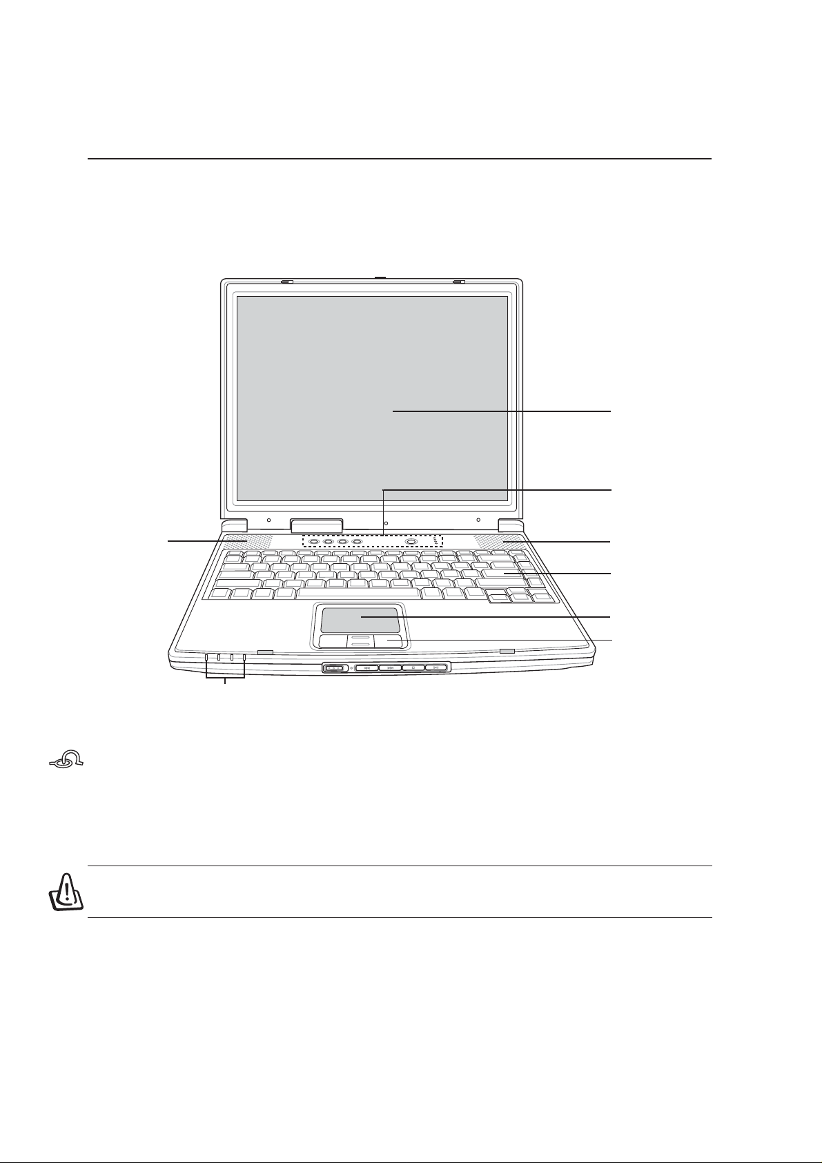
Refer to the diagram below to identify the components on the top side of the Notebook PC.
Display Panel Latch
One spring-loaded latch on the front of the Notebook PC locks the display panel in the closed position
when the Notebook PC is not in use. To open the display panel, slide and release the latch with your
thumb and lift up the display panel with the same thumb. Slowly tilt the display panel forward or
backward to a comfortable viewing angle.
WARNING! When opening, do not force the display panel down to the table or else
the hinges may break! Never lift the Notebook PC by the display panel!
Display Panel
Touchpad Buttons
Keyboard
Touchpad
Power Switch /
Instant Keys
Status Indicators
CD Control Buttons
(see section 3)
Display Panel Latch
Audio Speaker
(Right)
Audio Speaker
(Left)

15
Knowing the Parts 2
Display Panel
The display panel functions the same as a desktop monitor. The Notebook PC uses an active matrix
TFT LCD, which provides excellent viewing like that of desktop monitors. Unlike desktop monitors,
the LCD panel does not produce any radiation or flickering, so it is easier on the eyes.
Display Panel Care
The LCD screen is very delicate and requires careful handling. Pay attention to the following precautions:
• When not in use, keep the display panel closed to prevent dust accumulation.
• Do not use chemical cleaners on the screen. Wipe only with a dry cloth or tissue.
• Do not put your fingers or any objects directly on the screen.
• Do not press or lay any objects on the machine when it is closed.
• Do not carry the Notebook PC with small or sharp objects (e.g. paper clips or staples) that may
enter the Notebook PC and scratch the display panel.
Power Switch
The power switch allows powering ON and OFF the Notebook PC and recovering from STD. Push the
switch once to turn ON and once to turn OFF the Notebook PC.
Instant Launch Keys
Instant launch keys allow you to launch frequently used applications with one push of a button. Details
provided later in this manual.
Keyboard
The keyboard provides full-sized keys with comfortable travel (depth at which the keys can be de-
pressed) and palm rest for both hands. T wo W indows™ function keys are provided to help ease naviga-
tion in the Windows™ operating system.
Touchpad and Buttons
The touchpad with its buttons is a pointing device that provides the same functions as a desktop mouse.
A software-controlled scrolling function is available after setting up the included touchpad utility to
allow easy Windows or web navigation.
Status Indicators
Status indicator details are described in section 3.
16
2 Knowing the Parts
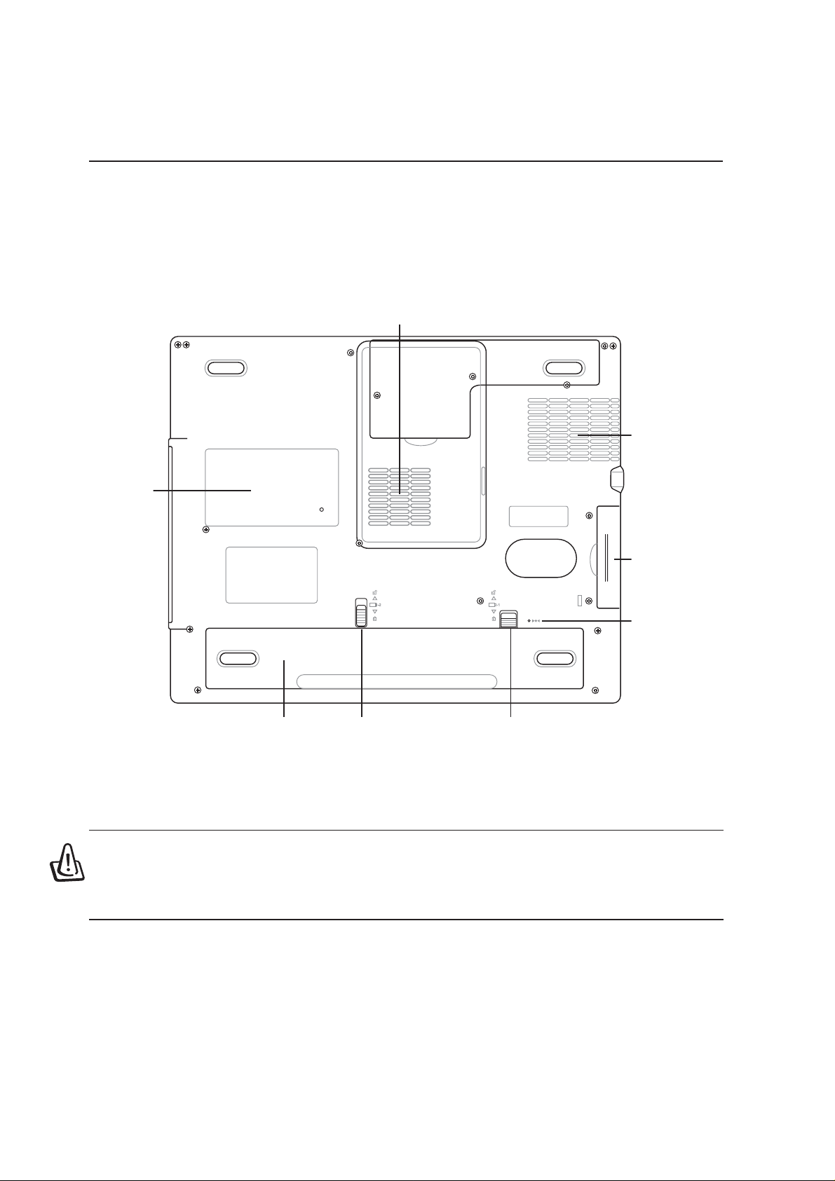
Bottom Side
Refer to the diagram below to identify the components on the bottom side of the Notebook PC.
WARNING! The bottom of the Notebook PC can get very hot. Be careful when han-
dling the Notebook PC while it is in operation or recently been in operation. High
temperatures are normal during charging or operation. DO NOT PUT THE NOTEBOOK
PC ON THE LAP OR OTHER P ARTS OF THE BODY T O AVOID INJURY FROM THE HEAT .
Name Card
Holder
Air Vents
Reset Button
Battery Pack
Battery Lock 1
Hard Disk Drive
Compartment
CPU & Memory
Compartment
Battery Lock 2
Air Vents

17
Knowing the Parts 2
Memory Compartment
The memory compartment contains 1 SO-DIMM slot for additional memory installation. Memory in-
stallation/upgrades must be done by an authorized retailer or else warranty will be void.
CPU Compartment
The CPU compartment contains a socket for mounting a central processing unit. CPU installation/
upgrades must be done by an authorized retailer or else warranty will be void.
Hard Disk Drive Compartment
The hard disk drive is secured in a compartment under a metal plate. Hard disk drive upgrades are to be
done by authorized service centers or dealers only.
Battery Pack
The battery pack is contained in a compartment covered by a door and locked by two tabs. Usage
details are described in the battery section later in this manual.
Air Vents
The air vents allow cool air to enter and warm air to exit the Notebook PC. Do not block the air vents or
else overheating may occur!
Shut Down Button
The shut down button is used for turning OFF the Notebook PC if <CTRL><ALT><DEL> or turning OFF
the power does not respond. T o use this function, momentarily depress the button within the hole with a pen
or paper clip and the Notebook PC will turn OFF . Do not use a pencil since the tip may break off in the hole.
18
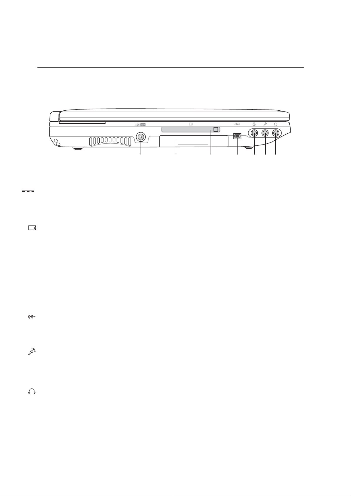
2 Knowing the Parts
Left Side
Refer to the diagram below to identify the components on the left side of the Notebook PC.
Microphone Input Jack (Mic-In)
The mono microphone jack can be used to connect an external microphone or output signals from audio
devices. Using this jack automatically disables the built-in microphone. Use this feature for video con-
ferencing, voice narrations, or simple audio recordings.
Headphone Output Jack (Head-Out)
The stereo headphone jack is used to connect the Notebook PC’ s audio out signal to amplified speakers
or headphones. Using this jack automatically disables the built-in speakers.
PC Card (PCMCIA) Socket
One PCMCIA 2.1 compliant socket is available to support one type I/II PC card. The socket supports
32-bit CardBus. This allows accommodation of Notebook PC expansion options such as memory cards,
ISDN, SCSI, Smart Cards, and wireless network adapters.
1
3
9
4
IEEE1394 Port
IEEE1394 is a high speed serial bus like SCSI but has simple connections and hot-plugging capabilities
like USB. The interface IEEE1394 has a bandwidth of 100-400 Mbits/sec and can handle up to 63 units
on the same bus. IEEE1394 is also used in high-end digital equipment and should be marked “DV” for
Digital V ideo port.
Audio Input Jack (Audio-In)
The stereo input jack can be used to connect an audio source to the Notebook PC. This feature is used
mainly to add audio to multimedia applications.
DC IN
DC Power Input Jack
The supplied power adapter converts AC power to DC power for use with this jack. Power supplied
through this jack supplies power to the Notebook PC and charges the internal battery pack. To prevent
damage to the Notebook PC and battery pack, always use the supplied power adapter.
Air Vents
IEEE1394PC Card
Socket
DC Power
Input Jack
Mic-In
Head-Out
Hard Drive
Compartment
Audio-In
19
Knowing the Parts 2
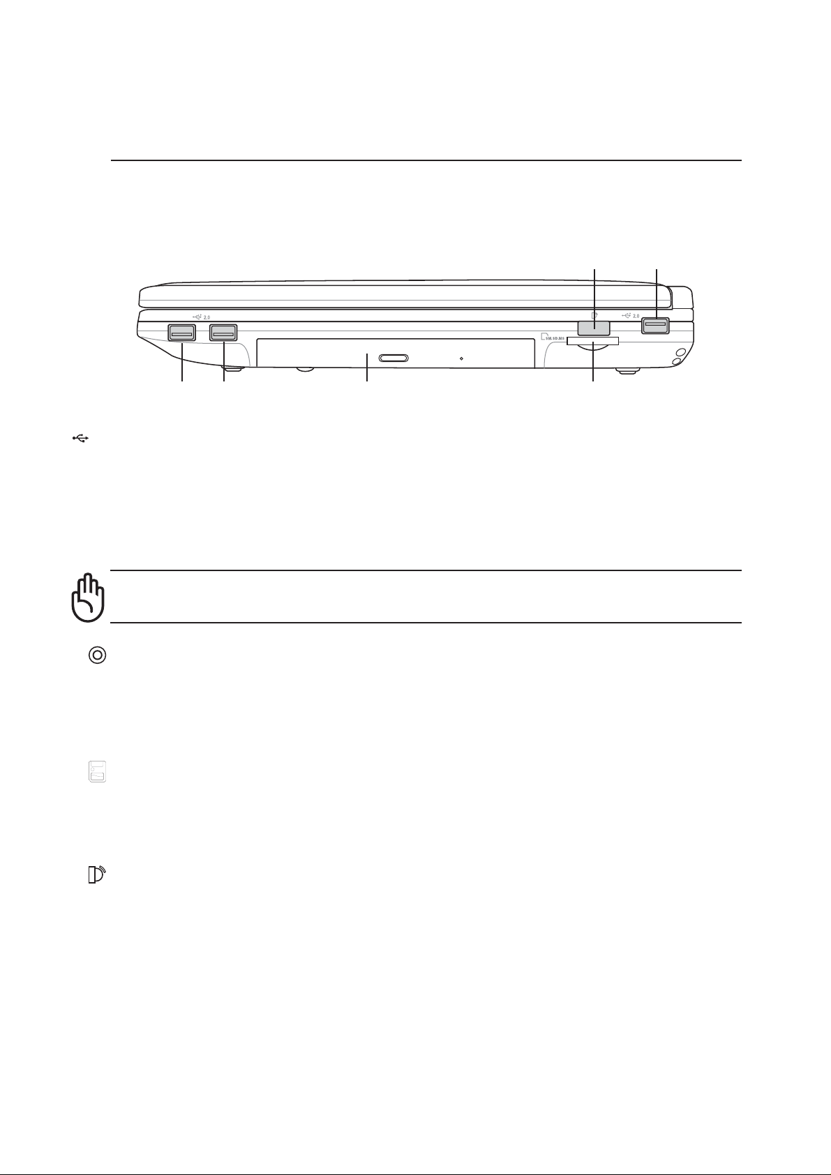
Right Side
Refer to the diagram below to identify the components on the right side of the Notebook PC.
Optical Drive Eject and Emergency Eject
The optical drive eject is an electronic eject button for opening the tray. You can also eject the optical
drive tray through any CD/VCD/DVD software player or by right clicking the optical drive in Win-
dows™ “My Computer.” The emergency eject is used to eject the optical drive tray in case the elec-
tronic eject does not work. Do not use the emergency eject in place of the electronic eject.
Flash Memory Card Reader (on selected models)
The built-in memory card reader can read the following flash memory cards: Secure Digital (SD),
Multi-Media Card (MMC), Memory Stick (MS), Memory Stick Select (MS Select), and Memory Stick
Duo (with MS adapter). This feature is only available on selected models.
Infrared Port (IrDA)
The infrared (IrDA) communication port allows convenient wireless data communication with infra-
red-equipped devices or computers. This allows easy wireless synchronization with PDAs or mobile
phones and even wireless printing to printers. If your office supports IrDA networking, you can have
wireless connection to a network anywhere provided there is a direct line of sight to an IrDA node.
Small offices can use IrDA technology to share a printer between several closely placed Notebook PCs
and even send files to each other without a network.
Memory
Reader
Infrared
Port
USB Ports
(Rotated 180 deg)
USB Port
Optical Drive
2
.0
USB Ports (1.1 & 2.0)
Universal Serial Bus (USB) supports many USB compatible devices such as keyboards, pointing de-
vices, video cameras, modems, hard disk drives, printers, monitors, and scanners connected in a series
up to 12Mbits/sec (USB 1.1) and 480Mbits/sec (USB 2.0). USB allows many devices to run simulta-
neously on a single computer, with peripherals such as USB keyboards and some newer monitors
acting as additional plug-in sites or hubs. USB supports hot-swapping of devices so that peripherals can
be connected or disconnected while the Notebook PC is turned ON.
CAUTION: The two USB ports on the right side is rotated 180 degrees compared to the
other USB ports. Be sure the orientation is correct before connecting your USB device.
20
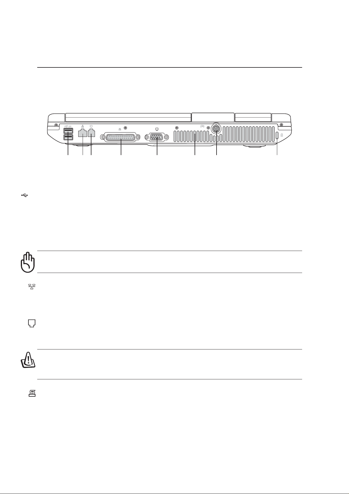
2 Knowing the Parts
Rear Side
Refer to the diagram below to identify the components on the rear side of the Notebook PC.
Parallel Port
The 25-pin D-sub parallel/printer port supports parallel devices such as printers, hard drives, removable
drives, or scanners.
LAN Port
The RJ-45 LAN port supports an RJ-45 Ethernet cable. The internal LAN supports 10Base-T or 100Base-
TX standard or duplex networks. The built-in connector allows convenient use without a dongle.
Modem Port
The RJ-11 telephone port supports an RJ-11 telephone cable. The internal modem supports up to 56K
V.90 transfers. The built-in connector allows convenient use without a dongle.
WARNING! The built-in modem does not support the voltage used in digital phone
systems. Do not connect the modem port to a digital phone system or else damage
will occur to the Notebook PC.
Modem Port
(RJ-1 1)
LAN Port
(RJ-45)
Monitor Port Air VentsUSB Ports Parallel Port
Kensington
®
Lock Port
TV Out Port
2
.0
USB Ports (1.1 & 2.0)
Universal Serial Bus (USB) supports many USB compatible devices such as keyboards, pointing de-
vices, video cameras, modems, hard disk drives, printers, monitors, and scanners connected in a series
up to 12Mbits/sec (USB 1.1) and 480Mbits/sec (USB 2.0). USB allows many devices to run simulta-
neously on a single computer, with peripherals such as USB keyboards and some newer monitors
acting as additional plug-in sites or hubs. USB supports hot-swapping of devices so that peripherals can
be connected or disconnected while the Notebook PC is turned ON.
CAUTION: The two USB ports on the right side is rotated 180 degrees compared to the
other USB ports. Be sure the orientation is correct before connecting your USB device.

21
Knowing the Parts 2
Monitor Port
The 15-pin D-sub monitor port supports a standard VGA-compatible device such as a monitor or pro-
jector to allow viewing on a larger external display.
TV-Out Port
For times when you need a really big display, try the TV-Out function. TV-Out allows a high definition
connection to a television or video projection device using a Super VHS (S-Video) cable (not pro-
vided). An adapter is provided for use with RCA inputs available on all standard video devices. This
port support NTSC or PAL formats.
T
V
Kensington
®
Lock Port
The Kensington
®
lock port allows the Notebook PC to be secured using Kensington
®
compatible Note-
book PC security products. These security products usually include a metal cable and lock that prevent
the Notebook PC to be removed from a fixed object. Some security products may also include a motion
detector to sound an alarm when moved.
K
Air Vents
The air vents allow cool air to enter and warm air to exit the Notebook PC. Do not block the air vents or
else overheating may occur!
 Loading...