


X99 WS-E/10G
X99 WS-E/10G
X99 WS-E
X99 WS-E

Version 1.0
Published November 2014
Copyright©2014 ASRock INC. All rights reserved.
Copyright Notice:
No part of this documentation may be reproduced, transcribed, transmitted, or translated in any language, in any form or by any means, except duplication of documentation by the purchaser for backup purpose, without written consent of ASRock Inc.
Products and corporate names appearing in this documentation may or may not be registered trademarks or copyrights of their respective companies, and are used only for identiication or explanation and to the owners’ beneit, without intent to
infringe.
Disclaimer:
Speciications and information contained in this documentation are furnished for informational use only and subject to change without notice, and should not be constructed as a commitment by ASRock. ASRock assumes no responsibility for any errors or omissions that may appear in this documentation.
With respect to the contents of this documentation, ASRock does not provide warranty of any kind, either expressed or implied, including but not limited to the implied warranties or conditions of merchantability or itness for a particular purpose.
In no event shall ASRock, its directors, oicers, employees, or agents be liable for any indirect, special, incidental, or consequential damages (including damages for loss of proits, loss of business, loss of data, interruption of business and the like), even if ASRock has been advised of the possibility of such damages arising from any defect or error in the documentation or product.
his device complies with Part 15 of the FCC Rules. Operation is subject to the following two conditions:
(1)this device may not cause harmful interference, and
(2)this device must accept any interference received, including interference that may cause undesired operation.
CALIFORNIA, USA ONLY
he Lithium battery adopted on this motherboard contains Perchlorate, a toxic substance controlled in Perchlorate Best Management Practices (BMP) regulations passed by the California Legislature. When you discard the Lithium battery in California, USA, please follow the related regulations in advance.
“Perchlorate Material-special handling may apply, see www.dtsc.ca.gov/hazardouswaste/ perchlorate”
ASRock Website: http://www.asrock.com

Manufactured under license under U.S. Patent Nos: 5,956,674; 5,974,380; 6,487,535; 7,003,467 & other U.S. and worldwide patents issued & pending. DTS, the Symbol, & DTS and the Symbol together is a registered trademark & DTS Connect, DTS Interactive, DTS Neo:PC are trademarks of DTS, Inc. Product includes sotware.
© DTS, Inc., All Rights Reserved.
Contents
Chapter 1 Introduction |
7 |
|
1.1 |
Package Contents |
7 |
1.2 |
Speciications |
8 |
1.3 |
Motherboard Layout |
13 |
1.4 |
I/O Panel |
19 |
Chapter 2 Installation |
23 |
|
2.1 |
Installing the CPU |
24 |
2.2 |
Installing the CPU Fan and Heatsink |
27 |
2.3 |
Installation of Memory Modules (DIMM) |
28 |
2.4 |
Expansion Slots (PCI Express Slots) |
30 |
2.5 |
Jumpers Setup |
31 |
2.6 |
Onboard Headers and Connectors |
32 |
2.7 |
Smart Switches |
38 |
2.8 |
Dr. Debug |
39 |
2.9SLITM , 3-Way SLITM , 4-Way SLITM and Quad SLITM Operation
|
Guide |
41 |
2.9.1 |
Installing Two SLITM-Ready Graphics Cards |
41 |
2.9.2 |
Installing Three SLITM-Ready Graphics Cards |
43 |
2.9.3 |
Installing Four SLITM-Ready Graphics Cards |
45 |
2.9.4 |
Driver Installation and Setup |
47 |
2.10CrossFireXTM, 3-Way CrossFireXTM, 4-Way CrossFireXTM and
Quad CrossFireXTM Operation Guide |
48 |
2.10.1 |
Installing Two CrossFireXTM-Ready Graphics Cards |
48 |
2.10.2 |
Installing Three CrossFireXTM-Ready Graphics Cards |
50 |
2.10.3 |
Installing Four CrossFireXTM-Ready Graphics Cards |
51 |
2.10.4 |
Driver Installation and Setup |
52 |
2.11 |
M.2_SSD (NGFF) Module Installation Guide |
53 |
2.12 |
SATA DOM (Disk on Module) Installation Guide |
56 |
2.13 |
Dual LAN and Teaming Operation Guide |
57 |
Chapter 3 Software and Utilities Operation |
58 |
|
3.1 |
Installing Drivers |
58 |
3.2 |
A-Tuning |
59 |
3.3 |
ASRock APP Shop |
65 |
3.3.1 |
UI Overview |
65 |
3.3.2 |
Apps |
66 |
3.3.3 |
BIOS & Drivers |
69 |
3.3.4 |
Setting |
70 |
3.4 |
Start8 |
71 |
Chapter 4 UEFI SETUP UTILITY |
74 |
|
4.1 |
Introduction |
74 |
4.1.1 |
UEFI Menu Bar |
74 |
4.1.2 |
Navigation Keys |
75 |
4.2 |
Main Screen |
76 |
4.3 |
OC Tweaker Screen |
77 |
4.4 |
Advanced Screen |
86 |
4.4.1 |
CPU Coniguration |
87 |
4.4.2 |
Chipset Coniguration |
89 |
4.4.3 |
Storage Coniguration |
92 |
4.4.4 |
Super IO Coniguration |
93 |
4.4.5 |
ACPI Coniguration |
94 |
4.4.6 |
USB Coniguration |
95 |
4.4.7 |
Trusted Computing |
96 |
4.5 |
Tools |
97 |
4.6 |
Hardware Health Event Monitoring Screen |
101 |
4.7 |
Security Screen |
103 |
4.8 |
Boot Screen |
104 |
4.9 |
Exit Screen |
107 |
X99 WS-E/10G / X99 WS-E
Chapter 1 Introduction
hank you for purchasing ASRock X99 WS-E/10G / X99 WS-E motherboard, a reliable motherboard produced under ASRock’s consistently stringent quality control. It delivers excellent performance with robust design conforming to ASRock’s commitment to quality and endurance.
In this documentation, Chapter 1 and 2 contains the introduction of the motherboard and step-by-step installation guides. Chapter 3 contains the operation guide of the sotware and utilities. Chapter 4 contains the coniguration guide of the BIOS setup.
Because the motherboard speciications and the BIOS sotware might be updated, the content of this documentation will be subject to change without notice. In case any modiications of this documentation occur, the updated version will be available on ASRock’s website without further notice. If you require technical support related to this motherboard, please visit our website for speciic information about the model you are using. You may ind the latest VGA cards and CPU support list on ASRock’s website as well. ASRock website http://www.asrock.com.
1.1 Package Contents
•ASRock X99 WS-E/10G / X99 WS-E Motherboard (EATX Form Factor)
•ASRock X99 WS-E/10G / X99 WS-E Quick Installation Guide
•ASRock X99 WS-E/10G / X99 WS-E Support CD
•1 x I/O Panel Shield
•1 x ASRock Flexible SLI Bridge Connector Cable (14 cm)
•1 x ASRock 3-Way SLI Bridge Card
•1 x ASRock 4-Way SLI Bridge Card
•6 x Serial ATA (SATA) Data Cables (Optional)
•1 x Screw for M.2 Socket
English
7

English
1.2 Speciications
Platform |
• |
EATX Form Factor |
|
• |
8 Layer PCB |
|
• 4 x 2oz Copper PCB |
|
|
• High Density Glass Fabric PCB |
|
CPU |
• |
Supports Intel® CoreTM i7 and Xeon® E5-1600/2600 v3 |
|
|
Processor Family for the LGA 2011-3 Socket, up to 18 Cores |
|
|
and 160W |
|
• |
Digi Power design |
|
• 12 Power Phase design |
|
|
• Supports Intel® Turbo Boost 2.0 Technology |
|
|
• Supports Untied Overclocking Technology |
|
Chipset |
• |
Intel® X99 |
Memory |
• |
Quad Channel DDR4 Memory Technology |
|
• 8 x DDR4 DIMM Slots |
|
|
• |
Supports DDR4 3200+(OC)*/2933(OC)/2800(OC)/2400 |
|
|
(OC)/2133/1866/ 1600/1333/1066 non-ECC, un-bufered |
|
|
memory |
|
* Please refer to Memory Support List on ASRock's website for |
|
|
|
more information. (http://www.asrock.com/) |
|
• Supports non-ECC RDIMM (Registered DIMM) |
|
|
• Supports DDR4 ECC, un-bufered memory/RDIMM with |
|
|
|
Intel® Xeon® processors E5 series in the LGA 2011-3 Socket |
|
• Max. capacity of system memory: 128GB (see CAUTION) |
|
|
• Supports Intel® Extreme Memory Proile (XMP) 2.0 |
|
|
• 15μ Gold Contact in DIMM Slots |
|
Expansion |
• |
7 x PCI Express 3.0 x16 Slots (PCIE1/PCIE2/PCIE3/PCIE4/ |
Slot |
|
PCIE5/PCIE6/PCIE7: single at x16 (PCIE7); dual at x16 |
|
|
(PCIE7) / x16 (PCIE3); triple at x16 (PCIE7) / x16 (PCIE5) / |
|
|
x16 (PCIE3); quad at x16 (PCIE7) / x16 (PCIE5) / x16 (PCIE3) |
/ x16 (PCIE1))
• 2 x embedded PLX PEX 8747
• Supports AMD Quad CrossFireXTM, 4-Way CrossFireXTM, 3-Way CrossFireXTM and CrossFireXTM
• Supports NVIDIA® Quad SLITM, 4-Way SLITM, 3-Way SLITM and SLITM
8

Audio
LAN
Rear Panel
I/O
X99 WS-E/10G / X99 WS-E
• 15μ Gold Contact in VGA PCIe Slot (PCIE1, PCIE3, PCIE5
and PCIE7) |
|
• 7.1 CH HD Audio with Content Protection (Realtek |
|
ALC1150 Audio Codec) |
|
• Premium Blu-ray Audio support |
|
• Supports Surge Protection (ASRock Full Spike Protection) |
|
• Supports Purity Sound™ 2 |
|
- Nichicon Fine Gold Series Audio Caps |
|
- 115dB SNR DAC with Diferential Ampliier |
|
- TI® NE5532 Premium Headset Ampliier (Supports up to |
|
600 Ohms headsets) |
|
- Direct Drive Technology |
|
- EMI Shielding Cover |
|
- PCB Isolate Shielding |
|
• Supports DTS Connect |
|
• 2 x Gigabit LAN 10/100/1000 Mb/s (Supported by 2 x Intel® |
|
I210AT) |
|
• 2 x 10G BASE-T LAN (Supported by Intel® X540 ) |
|
(for X99 WS-E/10G only) |
|
• Supports Wake-On-LAN |
|
• Supports Dual LAN with Teaming |
|
• Supports Quad LAN with Teaming (for X99 WS-E/10G |
|
only) |
|
• Supports Lightning/ESD Protection (ASRock Full Spike |
|
Protection) |
|
• Supports Energy Eicient Ethernet 802.3az |
|
• Supports PXE |
|
• 1 x Optical SPDIF Out Port |
|
• 1 x eSATA Connector |
|
• 4 x USB 2.0 Ports (Supports ESD Protection (ASRock Full |
|
Spike Protection)) |
|
• 4 x USB 3.0 Ports (ASMedia ASM1074 hub) (Supports ESD |
English |
LED) (for X99 WS-E) |
|
Protection (ASRock Full Spike Protection)) |
|
• 2 x RJ-45 LAN Ports with LED (ACT/LINK LED and SPEED |
|
• 4 x RJ-45 LAN Ports with LED (ACT/LINK LED and SPEED |
|
LED) (for X99 WS-E/10G) |
|
9

English
|
• 1 x Clear CMOS Switch |
|
• HD Audio Jacks: Rear Speaker / Central / Bass / Line in / |
|
Front Speaker / Microphone |
Storage |
• 10 x SATA3 6.0 Gb/s Connectors, support RAID (RAID |
|
0, RAID 1, RAID 5, RAID 10 and Intel Rapid Storage 13), |
|
NCQ, AHCI and Hot Plug |
|
(S_SATA3_2 is shared with the SATA DOM; S_SATA3_3 is |
|
shared with the eSATA) |
*RAID is supported on SATA3_0 ~ SATA3_5 ports only.
•2 x SATA3 6.0 Gb/s Connectors by Marvell SE9172, support RAID (RAID 0 and RAID 1), NCQ, AHCI and Hot Plug
*Marvell SE9172 RAID is supported with Windows® OS only.
•1 x SATA DOM Connector (shared with S_SATA3_2)
•1 x SATA Express 10 Gb/s Connector (shared with SATA3_4 and SATA3_5)
* Support to be announced
•1 x eSATA Connector, support NCQ, AHCI and Hot Plug
•1 x M.2_SSD (NGFF) Socket 3, supports M.2 SATA3 6.0 Gb/s module and M.2 PCI Express module up to Gen2 x 4 (20 Gb/s)
*If M2_1 is occupied by a SATA-type M.2 device, S_SATA3_0 will be disabled.
*If you install a M.2 PCI Express module and the SATA_EXP0 is in use, the M2_1 will downgrade to x2 mode.
Connector |
• 1 x COM Port Header |
|
• 1 x Chassis Intrusion Header |
|
• 1 x TPM Header |
|
• 1 x Power LED Header |
|
• 2 x CPU Fan Connectors (1 x 4-pin, 1 x 3-pin) |
|
• 3 x Chassis Fan Connectors (1 x 4-pin, 2 x 3-pin) (Smart Fan |
|
Speed Control) |
|
• 1 x Power Fan Connector (3-pin) |
|
• 1 x SB Fan Connector (3-pin) |
|
• 1 x 24 pin ATX Power Connector |
|
• 1 x 8 pin 12V Power Connector (Hi-Density Power |
|
Connector) |
|
• 1 x SATA DOM Power Header |
|
• 2 x PCIe Power Connectors |
10
X99 WS-E/10G / X99 WS-E
• 1 x SATA DOM Power Jumper
• 3 x SATA Serial General Purpose Input/Output Headers
• 1 x Front LAN LED Connector (for X99 WS-E)
• 2 x Front LAN LED Connectors (for X99 WS-E/10G)
• 1 x Front Panel Audio Connector
• 2 x USB 2.0 Headers (support 4 USB 2.0 ports) (Supports
ESD Protection (ASRock Full Spike Protection))
• 1 x USB DOM Connector
• 2 x USB 3.0 Headers (Support 4 USB 3.0 ports) (Supports
|
|
ESD Protection (ASRock Full Spike Protection)) |
|
• 1 x Dr. Debug with LED |
|
|
• 1 x Power Switch with LED |
|
|
• 1 x Reset Switch with LED |
|
|
• 1 x BIOS Selection Switch |
|
BIOS |
• |
2 x 128Mb AMI UEFI Legal BIOS with multilingual GUI |
Feature |
|
support (1 x Main BIOS and 1 x Backup BIOS) |
|
• Supports Secure Backup UEFI Technology |
|
|
• ACPI 1.1 Compliant wake up events |
|
|
• |
SMBIOS 2.3.1 Support |
|
• CPU, DRAM, PCH 1.05V, PCH 1.5V, VPPM Voltage Multi- |
|
|
|
adjustment |
Hardware |
• |
CPU/Chassis temperature sensing |
Monitor |
• |
CPU/Chassis/Power/SB Fan Tachometer |
|
• CPU/Chassis Quiet Fan (Auto adjust chassis fan speed by |
|
|
|
CPU temperature) |
|
• CPU/Chassis/SB Fan multi-speed control |
|
|
• Voltage monitoring: +12V, +5V, +3.3V, CPU Input Voltage, |
|
|
|
CPU Internal Voltages |
OS |
• |
Microsot® Windows® 10 64-bit / 8.1 32-bit / 8.1 64-bit / 8 |
|
|
32-bit / 8 64-bit / 7 32-bit / 7 64-bit / Server 2012 R2 64-bit / |
|
|
Server 2012 64-bit / Server 2008 R2 64-bit |
Certiica- |
• |
FCC, CE, WHQL |
tions |
• |
ErP/EuP Ready (ErP/EuP ready power supply is required) |
English
* For detailed product information, please visit our website: http://www.asrock.com
11
Please realize that there is a certain risk involved with overclocking, including adjusting the setting in the BIOS, applying Untied Overclocking Technology, or using third-party overclocking tools. Overclocking may afect your system’s stability, or even cause damage to the components and devices of your system. It should be done at your own risk and expense. We are not responsible for possible damage caused by overclocking.
Due to limitation, the actual memory size may be less than 4GB for the reservation for system usage under Windows® 32-bit operating systems. Windows® 64-bit operating systems do not have such limitations. You can use ASRock XFast RAM to utilize the memory that Windows® cannot use.
English
12
X99 WS-E/10G / X99 WS-E
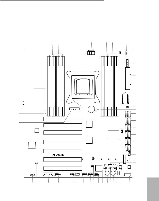
1.3 Motherboard Layout
X99 WS-E/10G
1 |
2 |
3 |
4 |
5 |
6 |
7 |
|
|
|
|
|
|
|
|
|
|
|
USB 2.0 |
Top: |
|
|
|
||||
|
T: USB1 |
|
|
||||||
|
RJ-45 |
|
|
|
|||||
|
B: USB2 |
|
|
||||||
|
|
|
|
|
|
||||
|
|
|
|
|
|
|
|
|
|
|
|
|
|
|
|
|
|
|
|
|
|
|
|
USB 3.0 |
|
|
LAN |
||
|
CLRC |
|
|
T: USB1 |
|
|
|
||
|
BTN1 |
|
|
|
|
||||
|
|
|
|
B: USB2 |
|
|
|||
|
|
|
|
|
|
|
|
|
|
|
|
|
|
|
|
|
|
|
|
|
USB 3.0 |
Top: |
|
|
|
||||
|
T: USB3 |
|
|
||||||
|
RJ-45 |
|
|
|
|||||
|
B: USB4 |
|
|
|
|
|
|||
|
|
|
|
|
|
|
|||
|
|
|
|
|
|
|
|
|
|
|
ESATA1 |
B: USB4 |
|
|
|||||
|
|
|
USB 2.0 |
|
|
||||
|
|
|
T: USB3 |
|
|
||||
|
|
|
|
|
|
|
|
|
|
|
|
|
|
|
|
|
|
|
LAN |
|
RJ-45 |
|
|
|
|
|
|
|
|
|
|
|
|
|
|
|
Intel |
||
|
|
|
|
|
|
|
|||
|
|
|
|
|
|
|
|||
|
RJ-45 |
|
|
|
|
X540 |
|||
|
|
|
|
|
|
|
|
||
46 |
|
|
|
|
|
|
|
|
|
|
|
|
|
|
|
|
|
|
|
|
SPDIF Optical Bottom: |
REARSPK |
Center: |
Central/Bass |
Top: |
|
|
||
|
MIC Bottom: IN |
FRONT |
Center: |
LINEIN |
Top: |
|
|
||
45 |
|
|
|
|
|
|
|
|
|
|
|
|
|
|
|
|
|
|
|
44 |
|
|
|
|
|
|
|
|
|
|
|
|
|
|
|
|
Super |
||
|
|
|
|
|
|
|
I/O |
||
|
|
|
Purity |
||||||
|
|
|
SoundT M 2 |
||||||
|
|
|
|
|
|
|
CI1 |
||
|
|
|
|
|
|
1 |
|
|
|
|
|
|
|
|
HD_AUDIO1 |
||||
|
|
|
|
1 |
|
|
|
|
|
|
|
|
|
|
|
|
|
|
|
ROHS
ATX12V1
|
|
|
|
|
2011-3 SOCKE T |
|
DDR4 A1(64bit,288-pinmodule) |
DDR4 A2(64bit,288-pinmodule) |
DDR4 B1(64bit,288-pinmodule) |
DDR4 B2(64bit,288-pinmodule) |
|
|
|
|
|
|
|
PCIE_PWR1 |
USB9 |
|
|
|
|
|
|
CMOS |
|
|
|
|
|
|
|
|
|
|
|
|
|
|
Battery |
PWR_FAN1 |
|
|
|
|
|
|
|
|
PCIE7 |
|
|
|
|
|
|
|
|
|
|
PEX |
|
|
PCIE6 |
|
|
8747 |
|
|
|
PCIE5 |
|
|
|
|
|
|
|
|
|
|
PEX |
|
|
PCIE4 |
|
|
8747 |
|
|
|
|
|
|
||
|
|
PCIE3 |
|
|
|
|
|
|
PCIE2 |
|
CT5 |
CT4 |
|
|
X99 WS-E/10G |
|
|
|
||
SSATA_SGPIO1
1
PCIE1
DDR4 D2(64bit,288-pinmodule) |
DDR4 D1(64bit,288-pinmodule) |
DDR4 C2(64bit,288-pinmodule) |
DDR4 C1(64bit,288-pinmodule) |
1


CLRMOS1
Intel
X99
CT3 |
|
|
|
CT2 |
|
|
CT1 |
||
|
PLED1 |
|
SPEAKER1 |
SATAPWR1 |
|||||
1 |
|
|
1 |
|
|
1 |
|
|
|
CPU_FAN2
|
CPU_FAN1 |
|
|
|
|
TPMS1 |
|
|
|
1 |
|
|
|
ATXPWR1 |
|
USB3_7_8 |
|
USB3_5_6 |
|
1 |
|
1 |
|
|
|
CHA_FAN3 |
|
|
SATA3_M0_M1 |
|
|
|
S_SATA3_2_3 |
|
|
SB_FAN1 |
SATA3_0_1 |
|
|
|
S_ |
|
|
1 |
_0_3 |
|
|
|
SATA3 |
|
|
|
SATA3_1_4 |
|
|
|
SATA3_2_5 |
|
|
|
|
SATAE_1 |
_EXP0 |
|
M2_1 |
BIOS_A_LED |
SATA |
|
|
CHA_FAN2 |
|
BIOS_B_LED |
|
|
|
BIOS_B |
|
BIOS_A |
|
Dr. |
SATA_SGPIO1 SATA_SGPIO2 |
BIOS_SEL1 |
128Mb |
128Mb |
||||||
Debug |
1 |
1 |
|
A |
|
|
|
B |
BIOS |
BIOS |
|
|
|
|
|
|
|||||
|
|
|
||||||||
|
|
|
|
|
|
|
|
|
|
|
SATA_PWR1
PCIE_PWR2 |
|
CHA_FAN1 |
|
|
|
|
SATA_0 |
COM1 |
FRONT_LAN_1 |
USB7_8 |
USB5_6 |
PLED PWRBTN |
|||
|
1 |
|
|
|
|
Reset |
Power |
|
|
|
|
|
|
|
|
1 |
1 |
|
1 |
1 |
1 |
|
|
FRONT_LAN_2 |
|
|
|
||||
|
|
|
HDLED |
RESET |
|
||
PANEL1
8
9
10
11
12
13
14
15
16
17
18
19
20
21
22
23
43 |
42 |
41 |
40 |
39 38 |
37 |
36 |
35 34 |
33 |
32 31 30 29 28 27 26 25 |
24 |
English
13

English
No. Description
1 2 x 288-pin DDR4 DIMM Slots (DDR4_A1, DDR4_B1) 2 2 x 288-pin DDR4 DIMM Slots (DDR4_A2, DDR4_B2)
3ATX 12V Power Connector (ATX12V1)
4 2 x 288-pin DDR4 DIMM Slots (DDR4_D2, DDR4_C2) 5 2 x 288-pin DDR4 DIMM Slots (DDR4_D1, DDR4_C1) 6 CPU Fan Connector (CPU_FAN2)
7 CPU Fan Connector (CPU_FAN1)
8TPM Header (TPMS1)
9 ATX Power Connector (ATXPWR1)
10USB 3.0 Header (USB3_7_8)
11USB 3.0 Header (USB3_5_6)
12Chassis Fan Connector (CHA_FAN3)
13Clear CMOS Jumper (CLRCMOS1)
14SATA3 Connectors (SATA3_M0_M1)
15SATA3 Connectors (S_SATA3_2_3)
16SATA3 Connectors (S_SATA3_0_1)
17SB Fan Connector (SB_FAN1)
18SATA3 Connectors (SATA3_0_3)
19SATA3 Connectors (SATA3_1_4)
20SATA3 Connectors (SATA3_2_5)
21SATA Express Connector (SATAE_1)
22Chassis Fan Connector (CHA_FAN2)
23Chassis Speaker Header (SPEAKER1)
24SATA DOM Connector (SATA_0)
25SATA DOM Power Jumper (SATAPWR1)
26SATA DOM Power Header (SATA_PWR1)
27BIOS Selection Switch (BIOS_SEL1)
28Power Switch (PWRBTN1)
29SATA SGPIO Connector (SATA_SGPIO2)
30Reset Switch (RSTBTN1)
31SATA SGPIO Connector (SATA_SGPIO1)
32Power LED Header (PLED1)
33System Panel Header (PANEL1)
34SATA SGPIO Connector (SSATA_SGPIO1)
14

X99 WS-E/10G / X99 WS-E
No. Description
35USB 2.0 Header (USB5_6)
36USB 2.0 Header (USB7_8)
37Chassis Fan Connector (CHA_FAN1)
38Front Lan LED Connector (FRONT_LAN_1)
39Front Lan LED Connector (FRONT_LAN_2)
40COM Port Header (COM1)
41PCIe Power Connector (PCIE_PWR2)
42Chassis Intrusion Header (CI1)
43Front Panel Audio Header (HD_AUDIO1)
44PCIe Power Connector (PCIE_PWR1)
45Power Fan Connector (PWR_FAN1)
46USB DOM Connector (USB9)
English
15

X99 WS-E |
|
|
|
|
|
|
|
|
|
|
|
|
|
|
|
|
|
|
|
|
||||||
|
|
|
|
|
|
|
1 |
|
2 |
|
|
|
|
3 |
|
|
|
4 |
5 |
|
|
6 |
|
7 |
|
|
|
|
|
|
|
|
|
|
|
ROHS |
|
|
|
|
|
|
|
|
|
|
|
|
|
|
|
|
|
USB 2.0 |
Top: |
|
|
|
|
|
|
|
|
|
|
|
|
|
|
|
|
|
|
|
|
|
||||
T: USB1 |
|
|
|
|
|
|
|
|
|
|
|
|
|
|
|
|
|
|
|
|
|
|||||
RJ-45 |
|
|
|
|
|
|
|
|
|
|
|
|
|
|
|
|
CPU_FAN2 |
|
|
|
|
|||||
B: USB2 |
|
|
|
|
|
|
|
|
|
|
|
|
|
|
|
|
|
|
|
|
||||||
|
|
|
|
|
|
|
|
|
|
|
ATX12V1 |
|
|
|
|
|
|
|
|
CPU_FAN1 |
|
|||||
|
|
|
|
|
|
|
|
|
|
|
|
|
|
|
|
|
|
|
|
|
|
|
|
TPMS1 |
|
|
|
|
USB 3.0 |
|
LAN |
|
|
|
|
|
|
|
|
|
|
|
|
|
|
|
|
|
|
|
|||
CLRC |
|
|
|
|
|
|
|
|
|
|
|
|
|
|
|
|
|
|
|
|
|
|
||||
|
T: USB1 |
|
|
|
|
|
|
|
|
|
|
|
|
|
|
|
|
|
|
|
|
8 |
||||
BTN1 |
|
|
|
|
|
|
|
|
|
|
|
|
|
|
|
|
|
|
|
|
|
|||||
|
B: USB2 |
|
|
|
|
|
|
|
|
|
|
|
|
|
|
|
|
|
|
|
|
|||||
|
|
|
|
|
|
|
|
|
|
|
|
|
|
|
|
|
|
|
|
|
|
|
||||
|
|
|
|
|
|
|
|
|
|
|
|
|
|
|
|
|
|
|
|
|
|
|
|
|
1 |
|
USB 3.0 |
Top: |
|
|
|
|
|
|
|
|
|
|
|
|
|
|
|
|
|
|
|
|
|
||||
T: USB3 |
|
|
|
|
|
|
|
|
|
|
|
|
|
|
|
|
|
|
|
|
|
|||||
RJ-45 |
|
|
|
|
|
|
|
|
|
|
|
|
|
|
|
|
|
|
|
|
|
|||||
B: USB4 |
|
|
|
|
|
|
|
|
|
|
|
|
|
|
|
|
|
|
|
|
|
|||||
|
|
|
|
module)pin-288 |
module)pin-288 |
module)pin-288 |
module)pin-288 |
|
|
|
|
|
|
module)pin-288 |
module)pin-288 |
module)pin-288 |
|
module)pin-288 |
|
|
ATXPWR1 |
|
||||
ESATA1 |
|
|
|
|
|
|
2011-3 SOCKE T |
|
|
|
|
|
|
|||||||||||||
|
|
|
|
|
|
|
|
|
|
|
|
|
|
|
|
|
|
|
|
|
|
|
|
|
|
9 |
|
USB 2.0 |
|
|
|
|
|
|
|
|
|
|
|
|
|
|
|
|
|
|
|
|
|
||||
|
T: USB3 |
|
|
|
|
|
|
|
|
|
|
|
|
|
|
|
|
|
|
|
|
|
||||
|
B: USB4 |
|
|
|
|
|
|
|
|
|
|
|
|
|
|
|
|
|
|
|
|
|
||||
|
|
|
|
|
|
|
LAN |
|
|
|
|
|
|
|
|
|
|
|
|
|
|
|
|
|
|
|
|
|
|
|
|
|
|
(64bit, |
(64bit, |
(64bit, |
(64bit, |
|
|
|
|
|
|
(64bit, |
(64bit, |
(64bit, |
|
(64bit, |
|
|
|
|
10 |
45 |
REARSPK |
|
Central/Bass |
|
|
|
A1 |
A2 |
B1 |
B2 |
|
|
|
|
|
|
D2 |
D1 |
C2 |
|
C1 |
USB37 8 |
|
USB35 6 |
|
|
SPDIF Optical Bottom: |
Center: |
Top: |
|
|
DDR4 |
DDR4 |
DDR4 |
DDR4 |
|
|
|
|
|
|
DDR4 |
DDR4 |
DDR4 |
|
DDR4 |
1 |
1 |
11 |
||||
MICIN Bottom: |
|
|
LINEIN |
Top: |
|
|
|
|
|
PCIE_PWR1 |
USB9 |
|
|
|
|
|
|
|
|
|
|
|
|
|
12 |
|
FRONT |
Center: |
|
|
|
|
|
|
|
|
|
|
|
|
|
|
|
|
|
|
|
||||||
|
|
|
|
|
|
|
|
Battery |
|
CLRMOS1 |
|
|
|
|
|
|
|
CHA_FAN3 |
13 |
|||||||
|
|
|
|
|
|
|
|
|
|
|
|
|
|
CMOS |
|
|
|
|
|
|
|
|
|
|
||
|
|
|
|
|
|
|
|
|
|
|
|
|
|
|
|
1 |
|
|
|
|
|
|
|
|
|
|
44 |
|
|
|
|
|
|
|
|
|
|
|
|
|
|
|
|
|
|
|
|
|
|
M0 M1 |
|
|
14 |
|
|
|
|
|
|
|
|
|
|
|
|
|
|
|
|
|
|
|
|
|
|
_ |
|
|
|
|
|
|
|
|
|
|
|
PWR_FAN1 |
|
|
|
|
|
|
|
|
|
|
|
|
|
|
|
SATA3 |
|
|
|
|
|
|
|
|
|
|
|
|
PCIE7 |
|
|
|
|
|
|
|
|
|
|
|
|
2 3 |
|
|
15 |
|
|
|
|
|
|
|
|
|
|
|
|
|
|
|
|
|
|
|
|
|
|
|
|
SATA3 |
|
|
|
43 |
|
|
|
|
|
|
|
|
|
|
|
|
PEX |
|
|
|
|
|
|
|
|
|
|
|
||
|
|
|
|
|
|
|
|
|
|
|
|
|
|
|
|
|
|
|
|
|
S |
|
|
|
||
|
|
|
|
|
|
|
|
|
PCIE6 |
|
|
8747 |
|
|
|
|
|
|
|
|
0 |
|
|
|
||
|
|
|
|
|
|
|
|
|
|
|
|
|
|
|
|
|
|
|
|
|
1 |
|
|
|
||
|
|
|
|
|
|
|
|
|
|
|
|
|
|
|
|
|
|
|
|
|
|
|
_ |
|
|
16 |
|
|
|
|
|
|
|
|
|
|
|
|
|
|
|
|
|
|
|
|
|
|
|
SATA3 |
|
|
|
|
|
|
|
|
|
|
|
|
|
|
|
|
|
|
|
|
|
|
|
|
|
SB_FAN1 |
|
|
|
|
|
|
|
|
|
|
Super |
|
|
|
|
|
|
|
|
|
|
|
|
|
|
|
|
S_ |
|
|
17 |
|
|
|
|
|
|
I/O |
|
|
PCIE5 |
|
|
|
|
|
|
|
|
|
|
|
|
|
|
|
||
|
|
|
|
|
|
|
|
|
|
|
|
|
|
|
|
|
Intel |
1 |
0 3 |
|
|
18 |
||||
|
|
|
|
|
|
|
|
|
|
|
|
|
|
|
|
|
|
|
|
|
|
|
SATA3 |
|
|
|
|
|
|
|
|
|
|
|
|
|
|
|
|
|
|
|
|
|
|
X99 |
|
|
|
|
|||
|
|
|
|
|
|
|
|
|
|
|
|
|
|
|
|
|
|
|
|
|
|
|
|
|||
|
|
|
|
|
|
|
|
|
|
|
|
|
PEX |
|
|
|
|
|
|
|
|
1 4 |
|
|
19 |
|
|
|
|
|
|
|
|
|
|
PCIE4 |
|
|
8747 |
|
|
|
|
|
|
|
|
_ |
|
|
|||
|
|
|
|
|
|
|
|
|
|
|
|
|
|
|
|
|
|
|
|
|
SATA3 |
|
|
|
||
|
|
|
|
|
|
|
|
|
|
|
|
|
|
|
|
|
|
|
|
|
|
|
|
|
|
|
|
Purity |
|
|
|
|
|
|
|
|
|
|
|
|
|
|
|
|
|
|
|
|
|
||||
|
Sound |
T M |
2 |
|
|
|
|
|
|
|
|
|
|
|
|
|
|
|
|
5 |
|
|
|
|||
|
|
|
|
|
|
|
|
|
|
|
|
|
|
|
|
|
|
2_ |
|
|
|
|||||
|
|
|
|
|
|
|
|
|
|
|
|
|
|
|
|
|
|
|
|
|
|
|
_ |
|
|
20 |
|
|
|
|
|
|
|
|
|
|
|
|
|
|
|
|
|
|
|
|
|
|
|
SATA3 |
|
|
|
|
|
|
|
|
|
|
|
|
|
|
|
|
|
|
|
|
|
|
|
|
|
|
|
|
|
|
|
|
|
|
|
|
|
|
|
PCIE3 |
|
|
|
|
|
|
|
|
|
|
|
|
|
1 |
EXP0 |
|
|
|
|
|
|
|
|
|
|
|
|
|
|
|
|
|
|
|
|
|
|
|
|
|
|
SATAE |
21 |
|
|
|
|
|
|
|
|
|
|
PCIE2 |
|
CT5 |
|
CT4 |
|
|
CT3 |
|
CT2 |
|
CT1 |
|
M21 |
BIOS A LED |
SATA |
22 |
|
|
|
|
|
|
|
|
|
|
|
|
|
|
|
|
|
|
|
|
|
|
|
|
|
|
CHA_FAN2 |
23 |
|
|
|
|
|
|
CI1 |
X99 WS-E |
|
|
|
|
|
|
|
|
|
|
|
|
|
|
|
||||
|
|
|
|
|
|
1 |
|
|
|
|
|
|
|
PLED1 |
SPEAKER1 |
SATAPWR1 |
BIOS_B_LED |
|
|
|
|
|||||
|
|
|
|
|
|
|
|
|
|
|
|
|
|
SSATA_SGPIO1 |
1 |
1 |
1 |
|
|
BIOS_B |
|
|
BIOS_A |
|
||
|
|
|
|
|
|
|
|
|
|
|
|
|
|
1 |
|
Dr. |
|
SATA_SGPIO1 |
SATA_SGPIO2 |
BIOS_SEL1 |
128Mb |
|
|
128Mb |
|
|
|
|
|
|
|
|
|
|
|
PCIE1 |
|
|
|
|
|
|
|
|
|
|
BIOS |
|
|
BIOS |
|
||
|
|
|
|
|
|
|
|
|
|
|
|
|
|
Debug |
1 |
1 |
A |
B |
|
|
|
|
|
|||
|
|
|
|
|
|
|
|
|
|
|
|
|
|
|
|
|
|
|
|
|
|
SATA_PWR1 |
|
|
|
|
|
|
|
|
|
|
|
PCIE_PWR2 |
|
|
FRONT_LAN_1 |
CHA_FAN1 |
|
|
|
|
|
|
|
|
|
|
|
|
SATA_0 |
|
|
|
|
|
HD_AUDIO1 |
|
|
COM1 |
USB7_8 |
|
USB5_6 |
PLED PWRBTN |
|
Reset |
Power |
|
|
|
|
|||||||||
|
|
|
|
|
|
1 |
|
|
|
|
|
|
|
|
|
|
|
|
|
|||||||
|
|
1 |
|
|
|
|
|
1 |
|
|
|
1 |
1 |
1 |
|
|
|
|
|
|
|
|
|
|
|
|
|
|
|
|
|
|
|
|
|
|
|
HDLED RESET |
|
|
|
|
|
|
|
|
|
|
|||||
|
|
|
|
|
|
|
|
|
|
|
|
|
|
|
|
PANEL1 |
|
|
|
|
|
|
|
|
|
|
|
|
|
42 |
41 |
40 |
|
39 |
38 |
37 |
36 |
|
35 34 |
33 |
32 31 30 29 28 27 26 25 |
|
|
24 |
|
||||||||
English
16

No. Description
1 2 x 288-pin DDR4 DIMM Slots (DDR4_A1, DDR4_B1) 2 2 x 288-pin DDR4 DIMM Slots (DDR4_A2, DDR4_B2)
3ATX 12V Power Connector (ATX12V1)
4 2 x 288-pin DDR4 DIMM Slots (DDR4_D2, DDR4_C2) 5 2 x 288-pin DDR4 DIMM Slots (DDR4_D1, DDR4_C1) 6 CPU Fan Connector (CPU_FAN2)
7 CPU Fan Connector (CPU_FAN1)
8TPM Header (TPMS1)
9 ATX Power Connector (ATXPWR1)
10USB 3.0 Header (USB3_7_8)
11USB 3.0 Header (USB3_5_6)
12Chassis Fan Connector (CHA_FAN3)
13Clear CMOS Jumper (CLRCMOS1)
14SATA3 Connectors (SATA3_M0_M1)
15SATA3 Connectors (S_SATA3_2_3)
16SATA3 Connectors (S_SATA3_0_1)
17SB Fan Connector (SB_FAN1)
18SATA3 Connectors (SATA3_0_3)
19SATA3 Connectors (SATA3_1_4)
20SATA3 Connectors (SATA3_2_5)
21SATA Express Connector (SATAE_1)
22Chassis Fan Connector (CHA_FAN2)
23Chassis Speaker Header (SPEAKER1)
24SATA DOM Connector (SATA_0)
25SATA DOM Power Jumper (SATAPWR1)
26SATA DOM Power Header (SATA_PWR1)
27BIOS Selection Switch (BIOS_SEL1)
28Power Switch (PWRBTN1)
29SATA SGPIO Connector (SATA_SGPIO2)
30Reset Switch (RSTBTN1)
31SATA SGPIO Connector (SATA_SGPIO1)
32Power LED Header (PLED1)
33System Panel Header (PANEL1)
34SATA SGPIO Connector (SSATA_SGPIO1)
X99 WS-E/10G / X99 WS-E
English
17

No. Description
35USB 2.0 Header (USB5_6)
36USB 2.0 Header (USB7_8)
37Chassis Fan Connector (CHA_FAN1)
38Front Lan LED Connector (FRONT_LAN_1)
39COM Port Header (COM1)
40PCIe Power Connector (PCIE_PWR2)
41Chassis Intrusion Header (CI1)
42Front Panel Audio Header (HD_AUDIO1)
43PCIe Power Connector (PCIE_PWR1)
44Power Fan Connector (PWR_FAN1)
45USB DOM Connector (USB9)
English
18
X99 WS-E/10G / X99 WS-E
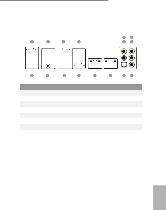
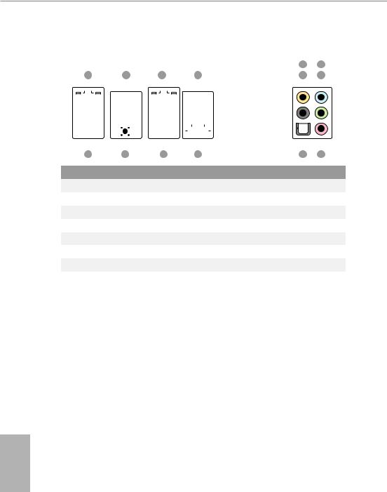
1.4 I/O Panel
X99 WS-E/10G
|
|
|
|
|
|
|
|
|
|
|
|
|
|
|
|
|
|
|
|
|
|
|
|
|
5 |
7 |
||||||||||||||||
|
1 |
|
|
|
2 |
|
|
|
3 |
|
|
|
|
|
4 |
|
6 |
8 |
||||||||||||||||||||||||
|
|
|
|
|
|
|
|
|
|
|
|
|
|
|
|
|
|
|
|
|
|
|
|
|
|
|
|
|
|
|
|
|
|
|
|
|
|
|
|
|
|
|
|
|
|
|
|
|
|
|
|
|
|
|
|
|
|
|
|
|
|
|
|
|
|
|
|
|
|
|
|
|
|
|
|
|
|
|
|
|
|
|
|
|
|
|
|
|
|
|
|
|
|
|
|
|
|
|
|
|
|
|
|
|
|
|
|
|
|
|
|
|
|
|
|
|
|
|
|
|
|
|
|
|
|
|
|
|
|
|
|
|
|
|
|
|
|
|
|
|
|
|
|
|
|
|
|
|
|
|
|
|
|
|
|
|
|
|
|
|
|
|
|
|
|
|
|
|
|
|
|
|
|
|
|
|
|
|
|
|
|
|
|
|
|
|
|
|
|
|
|
|
|
|
|
|
|
|
|
|
|
|
|
|
|
|
|
|
|
|
|
|
|
|
|
|
|
|
|
|
|
|
|
|
|
|
|
|
|
|
|
|
|
|
|
|
|
|
|
|
|
|
|
|
|
|
|
|
|
|
|
|
|
|
|
|
|
|
|
|
|
|
|
|
|
|
|
|
|
|
|
|
|
|
|
|
|
|
|
|
|
|
|
|
|
|
|
|
|
|
|
|
|
|
|
|
|
|
|
|
|
|
|
|
|
|
|
|
|
|
|
|
|
|
|
|
|
|
|
|
|
|
|
|
|
|
|
|
|
|
|
|
|
|
|
|
|
|
|
|
|
|
|
|
|
|
|
|
|
|
|
|
|
|
|
|
|
|
|
|
|
|
|
|
|
|
|
|
|
|
|
|
|
|
|
|
|
|
|
|
|
|
|
|
|
|
|
|
|
|
|
|
|
|
|
|
|
|
|
|
|
|
|
|
|
|
|
|
|
|
|
|
|
|
|
|
|
|
|
|
|
|
|
|
|
|
|
|
|
|
|
|
|
|
|
|
|
|
|
|
|
|
|
|
|
|
|
|
|
|
|
|
|
|
|
|
|
|
|
|
|
|
|
|
|
|
|
|
|
|
|
|
|
|
|
|
|
|
|
|
|
|
|
|
|
|
|
|
|
|
|
|
|
|
|
|
|
|
|
|
|
|
|
|
|
|
|
|
|
|
|
|
|
|
|
|
16 |
15 |
14 |
13 |
|
12 |
11 |
10 |
9 |
No. |
Description |
|
|
|
No. |
Description |
|
|
|
|
|
|
|
|
|
||||
1 |
LAN RJ-45 Port (Intel® I210AT)* |
|
9 |
Microphone (Pink) |
|
|
|||
2 |
USB 3.0 Ports (USB3_12) |
|
|
10 |
Optical SPDIF Out Port |
|
|||
3 |
LAN RJ-45 Port (Intel® I210AT)* |
|
11 |
LAN RJ-45 Port (Intel® X540)* |
|||||
4 |
USB 2.0 Ports (USB34) |
|
|
12 |
LAN RJ-45 Port (Intel® X540)* |
||||
5 |
Central / Bass (Orange) |
|
|
13 |
eSATA Connector (eSATA1)*** |
||||
6 |
Rear Speaker (Black) |
|
|
14 |
USB 3.0 Ports (USB3_34) |
|
|||
7 |
Line In (Light Blue) |
|
|
15 |
Clear CMOS Switch |
|
|
||
8 |
Front Speaker (Lime)** |
|
|
16 |
USB 2.0 Ports (USB2_12) |
|
|||
|
|
|
|
|
|
|
|
|
|
English
19
X99 WS-E
|
|
|
|
|
|
|
|
|
|
|
|
|
|
|
|
|
|
|
|
|
|
|
|
|
5 |
7 |
||
|
1 |
|
|
|
2 |
|
|
|
3 |
|
|
|
|
|
4 |
|
6 |
8 |
||||||||||
|
|
|
|
|
|
|
|
|
|
|
|
|
|
|
|
|
|
|
|
|
|
|
|
|
|
|
|
|
|
|
|
|
|
|
|
|
|
|
|
|
|
|
|
|
|
|
|
|
|
|
|
|
|
|
|
|
|
|
|
|
|
|
|
|
|
|
|
|
|
|
|
|
|
|
|
|
|
|
|
|
|
|
|
|
|
|
|
|
|
|
|
|
|
|
|
|
|
|
|
|
|
|
|
|
|
|
|
|
|
|
|
|
|
|
|
|
|
|
|
|
|
|
|
|
|
|
|
|
|
|
|
|
|
|
|
|
|
|
|
|
|
|
|
|
|
|
|
|
|
|
|
|
|
|
|
|
|
|
|
|
|
|
|
|
|
|
|
|
|
|
|
|
|
|
|
|
|
|
|
|
|
|
|
|
|
|
|
|
|
|
|
|
|
|
|
|
|
|
|
|
|
|
|
|
|
|
|
|
|
|
|
|
|
|
|
|
|
|
|
|
|
|
|
|
|
|
|
|
|
|
|
|
|
|
|
|
|
|
|
|
|
|
|
|
|
|
|
|
|
|
|
|
|
|
|
|
|
|
|
|
|
|
|
|
|
|
|
|
|
|
|
|
|
|
|
|
|
|
|
|
|
|
|
|
|
|
|
|
|
|
|
|
|
|
|
|
|
|
|
|
|
|
|
|
|
|
|
|
|
|
|
|
|
|
|
|
|
|
|
|
|
|
|
|
|
|
|
|
|
|
|
|
|
|
|
|
|
|
|
|
|
|
|
|
|
|
|
|
|
|
|
|
|
|
|
|
|
|
|
|
|
|
|
|
|
|
|
|
|
|
|
|
|
|
|
|
|
|
|
|
|
|
|
|
|
|
|
|
|
|
|
|
|
|
|
|
|
|
|
|
|
|
|
|
|
|
|
|
|
|
|
|
|
|
|
|
|
|
|
|
|
|
|
|
|
|
|
|
|
|
|
|
|
|
|
|
|
|
|
|
|
|
|
|
|
|
|
|
|
|
|
|
|
|
|
|
|
|
|
|
|
|
|
|
14 |
13 |
12 |
11 |
|
10 |
9 |
No. |
Description |
|
|
|
No. |
Description |
|
|
|
|
|
||||
1 |
LAN RJ-45 Port (Intel® I210AT)* |
|
8 |
Front Speaker (Lime)** |
|
||
2 |
USB 3.0 Ports (USB3_12) |
|
|
9 |
Microphone (Pink) |
|
|
3 |
LAN RJ-45 Port (Intel® I210AT)* |
|
10 |
Optical SPDIF Out Port |
|
||
4 |
USB 2.0 Ports (USB34) |
|
|
11 |
eSATA Connector (eSATA1)*** |
||
5 |
Central / Bass (Orange) |
|
|
12 |
USB 3.0 Ports (USB3_34) |
|
|
6 |
Rear Speaker (Black) |
|
|
13 |
Clear CMOS Switch |
|
|
7 |
Line In (Light Blue) |
|
|
14 |
USB 2.0 Ports (USB2_12) |
|
|
|
|
|
|
|
|
|
|
English
20
X99 WS-E/10G / X99 WS-E
* here are two LEDs on each LAN port. Please refer to the table below for the LAN port LED indications.
1G (Intel® I210AT):
ACT/LINK LED
|
|
SPEED LED |
|
|
|
|
|
|
|||
|
|
|
|
|
|
|
|
|
|
|
|
|
|
|
|
|
|
|
|
|
|
|
|
|
|
|
|
|
|
|
|
|
|
|
|
|
|
|
|
|
|
|
|
|
|
|
|
|
|
|
|
|
|
|
|
|
|||
|
LAN Port |
|
|
|
|
|
|
||||
Activity / Link LED |
|
Speed LED |
|
|
|||||||
|
|
|
|||||||||
Status |
|
Description |
|
Status |
|
Description |
|||||
Of |
|
No Link |
|
Of |
|
10Mbps connection |
|||||
|
|
|
|||||||||
Blinking |
|
Data Activity |
|
Orange |
|
100Mbps connection |
|||||
On |
|
Link |
|
Green |
|
1Gbps connection |
|||||
|
|
|
|
|
|
|
|
|
|
|
|
10G (Intel® X540):
SPEED LED
ACT/LINK LED
LAN Port
Speed LED |
|
|
Activity / Link LED |
||
Status |
|
Description |
Status |
|
Description |
Of |
|
100Mbps connection or |
Of |
|
No Link |
|
|
||||
|
|
no link |
|
|
|
Yellow |
|
1Gbps connection |
Blinking Green |
|
Data Activity |
Green |
|
10Gbps connection |
On |
|
Link |
|
|
|
|
|
|
Please note that Cat-6 or higher cabling is required for 10G BASE-T. For 10G BASE-TLAN, the maximum cable length is 55 meters.
*Cat-6A can run up to 100 meters.
English
21
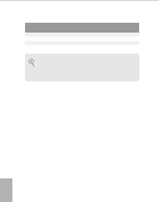
** If you use a 2-channel speaker, please connect the speaker’s plug into “Front Speaker Jack”. See the table below for connection details in accordance with the type of speaker you use.
Audio Output |
Front Speaker |
Rear Speaker |
Central / Bass |
Line In |
Channels |
(No. 8) |
(No. 6) |
(No.5) |
(No. 7) |
2 |
V |
-- |
-- |
-- |
4 |
V |
V |
-- |
-- |
6 |
V |
V |
V |
-- |
8 |
V |
V |
V |
V |
To enable Multi-Streaming, you need to connect a front panel audio cable to the front panel audio header. Ater restarting your computer, you will ind the “Mixer” tool on your system. Please select “Mixer ToolBox”  , click “Enable playback multi-streaming”, and click “ok”. Choose “2CH”, “4CH”, “6CH”, or “8CH” and then you are allowed to select “Realtek HDA Primary output” to use the Rear Speaker, Central/Bass, and Front Speaker, or select “Realtek HDA Audio 2nd output” to use the front panel audio.
*** he eSATA connector supports SATA with cables within 1 meters. he S_SATA3_3 connector is shared with the eSATA1 port.
English
22

X99 WS-E/10G / X99 WS-E
Chapter 2 Installation
his is an EATX form factor motherboard. Before you install the motherboard, study the coniguration of your chassis to ensure that the motherboard its into it.
Pre-installation Precautions
Take note of the following precautions before you install motherboard components or change any motherboard settings.
•Make sure to unplug the power cord before installing or removing the motherboard components. Failure to do so may cause physical injuries and damages to motherboard components.
•In order to avoid damage from static electricity to the motherboard’s components, NEVER place your motherboard directly on a carpet. Also remember to use a grounded wrist strap or touch a safety grounded object before you handle the components.
•Hold components by the edges and do not touch the ICs.
•Whenever you uninstall any components, place them on a grounded anti-static pad or in the bag that comes with the components.
•When placing screws to secure the motherboard to the chassis, please do not overtighten the screws! Doing so may damage the motherboard.
English
23
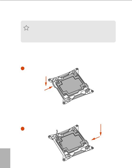
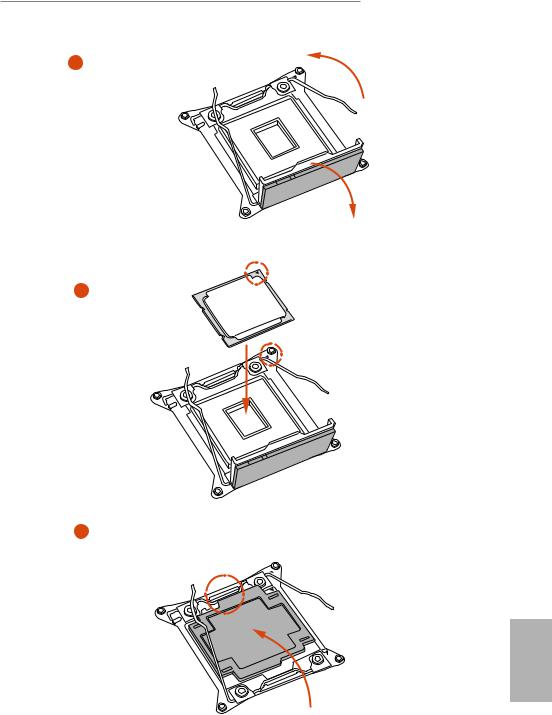
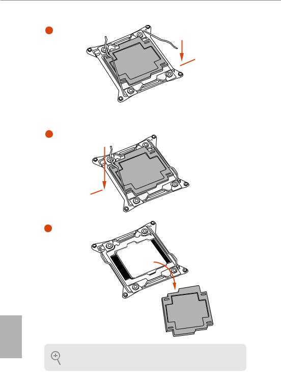
2.1Installing the CPU
1.Before you insert the 2011-3-Pin CPU into the socket, please check if the PnP cap is on the socket, if the CPU surface is unclean, or if there are any bent pins in the socket. Do not force to insert the CPU into the socket if above situation is found. Otherwise, the CPU will be seriously damaged.
2.Unplug all power cables before installing the CPU.
CAUTION:
Please note that X99 platform is only compatible with the LGA 2011-3 socket, which is
incompatible with the LGA 2011 socket (for X79 platform).
1
A
B
A
2
English
24
X99 WS-E/10G / X99 WS-E
A
3
B
4
5
English
25
6
A
 B
B
7
A
B
8
English
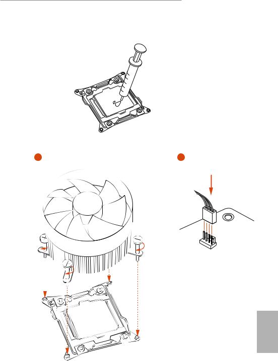
Please save and replace the cover if the processor is removed. he cover must be placed if you wish to return the motherboard for ater service.
26
X99 WS-E/10G / X99 WS-E
2.2 Installing the CPU Fan and Heatsink
|
|
|
1 |
2 |
|
_FAN CPU
English
27
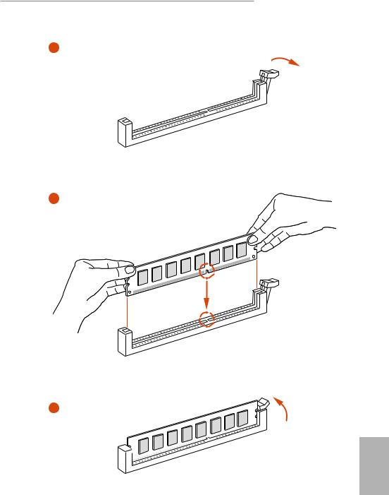
2.3 Installation of Memory Modules (DIMM)
his motherboard provides eight 288-pin DDR4 (Double Data Rate 4) DIMM slots, and
supports Quad Channel Memory Technology.
1. For quad channel coniguration, you always need to install identical (the same brand, speed, size and chip-type) DDR4 DIMM pairs.
2.It is not allowed to install a DDR, DDR2 or DDR3 memory module into a DDR4 slot; otherwise, this motherboard and DIMM may be damaged.
3.he DIMM only its in one correct orientation. It will cause permanent damage to the motherboard and the DIMM if you force the DIMM into the slot at incorrect orientation.
Quad Channel Memory Coniguration
Priority |
1 |
2 |
|
DDR4_A1 |
Populated |
|
Populated |
|
|||
|
|
|
|
DDR4_A2 |
|
|
Populated |
|
|
|
|
DDR4_B1 |
Populated |
|
Populated |
|
|
|
|
DDR4_B2 |
|
|
Populated |
|
|
|
|
DDR4_C1 |
Populated |
|
Populated |
|
|
|
|
DDR4_C2 |
|
|
Populated |
|
|
|
|
DDR4_D1 |
Populated |
|
Populated |
|
|
|
|
DDR4_D2 |
|
|
Populated |
|
|
|
|
•Due to Intel® CPU spec deinition, please install the memory modules on DDR4_A1, DDR4_B1, DDR4_C1 and DDR4_D1 for irst priority. If the four DDR4 DIMM slots above are fully installed, and you want to use more than four memory modules, please install the other memory modules from let to right (from DDR4_A2, DDR4_B2, DDR4_D2 to DDR4_C2.)
•If only two memory modules are installed in the DDR4 DIMM slots, then Dual Channel Memory Technology is activated. If three memory modules are installed, then Triple Channel Memory Technology is activated. If more than four memory modules are installed in the DDR4 DIMM slots, then Quad Channel Memory Technology is activated.
English
28
X99 WS-E/10G / X99 WS-E
1
2
3
English
29

English
2.4 Expansion Slots (PCI Express Slots)
here are 7 PCI Express slots on the motherboard.
Before installing an expansion card, please make sure that the power supply is switched of or the power cord is unplugged. Please read the documentation of the expansion card and make necessary hardware settings for the card before you start the installation.
PCIe slots:
PCIE1 (PCIe 3.0 x16 slot) is used for PCI Express x16 lane width graphics cards. PCIE2 (PCIe 3.0 x16 slot) is used for PCI Express x8 lane width graphics cards. PCIE3 (PCIe 3.0 x16 slot) is used for PCI Express x16 lane width graphics cards. PCIE4 (PCIe 3.0 x16 slot) is used for PCI Express x8 lane width graphics cards. PCIE5 (PCIe 3.0 x16 slot) is used for PCI Express x16 lane width graphics cards. PCIE6 (PCIe 3.0 x16 slot) is used for PCI Express x8 lane width graphics cards. PCIE7 (PCIe 3.0 x16 slot) is used for PCI Express x16 lane width graphics cards.
|
PCIE1 |
PCIE2 |
PCIE3 |
PCIE4 |
PCIE5 |
PCIE6 |
PCIE7 |
|
Single Graphics Card |
N/A |
N/A |
N/A |
N/A |
N/A |
N/A |
x16 |
|
Two Graphics Cards |
|
|
|
|
|
|
|
|
in |
N/A |
N/A |
x16 |
N/A |
N/A |
N/A |
x16 |
|
CrossFireXTM or SLITM |
||||||||
|
|
|
|
|
|
|
||
Mode |
|
|
|
|
|
|
|
|
hree Graphics |
|
|
|
|
|
|
|
|
Cards in 3-Way |
N/A |
N/A |
x16 |
N/A |
x16 |
N/A |
x16 |
|
CrossFireXTM Mode |
||||||||
|
|
|
|
|
|
|
||
or 3-Way SLITM Mode |
|
|
|
|
|
|
|
|
Four Graphics Cards |
|
|
|
|
|
|
|
|
in |
|
|
|
|
|
|
|
|
4-Way CrossFireXTM |
x16 |
N/A |
x16 |
N/A |
x16 |
N/A |
x16 |
|
Mode |
|
|
|
|
|
|
|
|
or 4-Way SLITM Mode |
|
|
|
|
|
|
|
For a better thermal environment, please connect a chassis fan to the motherboard’s chassis fan connector (CHA_FAN1, CHA_FAN2 or CHA_FAN3) when using multiple graphics cards.
30
 Loading...