


P4V88-M+
User Manual
Version 1.0
Published May 2005
Copyright©2005 ASRock INC. All rights reserved.
1
Copyright Notice:
No part of this manual may be reproduced, transcribed, transmitted, or translated in any language, in any form or by any means, except duplication of documentation by the purchaser for backup purpose, without written consent of ASRock Inc.
Products and corporate names appearing in this manual may or may not be registered trademarks or copyrights of their respective companies, and are used only for identification or explanation and to the owners’ benefit, without intent to infringe.
Disclaimer:
Specifications and information contained in this manual are furnished for informational use only and subject to change without notice, and should not be constructed as a commitment by ASRock. ASRock assumes no responsibility for any errors or omissions that may appear in this manual.
With respect to the contents of this manual, ASRock does not provide warranty of any kind, either expressed or implied, including but not limited to the implied warranties or conditions of merchantability or fitness for a particular purpose.
In no event shall ASRock, its directors, officers, employees, or agents be liable for any indirect, special, incidental, or consequential damages (including damages for loss of profits, loss of business, loss of data, interruption of business and the like), even if ASRock has been advised of the possibility of such damages arising from any defect or error in the manual or product.
This device complies with Part 15 of the FCC Rules. Operation is subject to the following two conditions:
(1)this device may not cause harmful interference, and
(2)this device must accept any interference received, including interference that may cause undesired operation.
ASRock Website: http://www.asrock.com
2

Contents
1. Introduction .................................................. |
5 |
||
1.1 |
Package Contents .......................................................... |
5 |
|
1.2 |
Specifications ................................................................ |
6 |
|
1.3 |
Motherboard Layout ...................................................... |
8 |
|
1.4 |
ASRock I/O PlusTM ................................................................................................. |
9 |
|
2. Installation .................................................... |
10 |
||
Pre-installation Precautions ................................................... |
10 |
||
2.1 |
CPU Installation .............................................................. |
11 |
|
2.2 |
Installation of CPU Fan and Heatsink ............................ |
11 |
|
2.3 |
Installation of Memory Modules (DIMM) ......................... |
12 |
|
2.4 |
Expansion Slots (PCI and AGP Slots) ........................... |
13 |
|
2.5 |
Jumpers Setup .............................................................. |
14 |
|
2.6 |
Onboard Headers and Connectors .............................. |
15 |
|
2.7 |
Serial ATA (SATA) Hard Disks Installation ..................... |
18 |
|
2.8 |
Hot Plug and Hot Swap Functions for SATA HDDs ....... |
18 |
|
2.9 |
Installing Windows 2000 / Windows XP With RAID |
|
|
|
Functions ..................................................................... |
19 |
|
2.10 Installing Windows 98 / ME / 2000 / XP Without RAID |
|
||
|
Functions ..................................................................... |
20 |
|
3. BIOS SETUP UTILITY ......................................... |
21 |
||
3.1 |
Introduction .................................................................... |
21 |
|
|
3.1.1 BIOS Menu Bar .................................................... |
21 |
|
|
3.1.2 Navigation Keys ................................................... |
22 |
|
3.2 |
Main Screen ................................................................... |
22 |
|
3.3 |
Advanced Screen ......................................................... |
23 |
|
|
3.3.1 CPU Configuration ................................................ |
23 |
|
|
3.3.2 |
Chipset Configuration .......................................... |
24 |
|
3.3.3 ACPI Configuration ............................................... |
26 |
|
|
3.3.4 IDE Configuration ................................................. |
27 |
|
|
3.3.5 PCIPnP Configuration ........................................... |
29 |
|
|
3.3.6 |
Floppy Configuration ........................................... |
29 |
|
3.3.7 |
Super IO Configuration ........................................ |
30 |
|
3.3.8 |
USB Configuration ............................................... |
31 |
3.4 |
Hardware Health Event Monitoring Screen .................. |
32 |
|
3.5 |
Boot Screen ................................................................... |
32 |
|
|
3.5.1 Boot Settings Configuration .................................. |
33 |
|
|
3.5.2 Boot Device Priority ............................................... |
33 |
|
3.6 |
Security Screen ............................................................ |
34 |
|
3.7 |
Exit Screen .................................................................... |
35 |
|
3

4. Software Support .......................................... |
36 |
4.1 |
Install Operating System ............................................... |
36 |
|
4.2 |
Support CD Information ................................................. |
36 |
|
|
4.2.1 Running Support CD ............................................ |
36 |
|
|
4.2.2 Drivers Menu ........................................................ |
36 |
|
|
4.2.3 |
Utilities Menu ........................................................ |
36 |
|
4.2.4 |
Contact Information .............................................. |
36 |
4
1. Introduction
Thank you for purchasing ASRock P4V88-M+ motherboard, a reliable motherboard produced under ASRock’s consistently stringent quality control. It delivers excellent performance with robust design conforming to ASRock’s commitment to quality and endurance.
In this manual, chapter 1 and 2 contain introduction of the motherboard and step-by- step guide to the hardware installation. Chapter 3 and 4 contain the configuration guide to BIOS setup and information of the Support CD.
Because the motherboard specifications and the BIOS software might be updated, the content of this manual will be subject to change without notice. In case any modifications of this manual occur, the updated version will be available on ASRock website without further notice. You may find the latest memory and CPU support lists on ASRock website as well. ASRock website http://www.asrock.com
1.1 Package Contents
ASRock P4V88-M+ Motherboard
(Micro ATX Form Factor: 9.6-in x 8.5-in, 24.4 cm x 21.6 cm) ASRock P4V88-M+ Quick Installation Guide
ASRock P4V88-M+ Support CD
One 80-conductor Ultra ATA 66/100/133 IDE Ribbon Cable One Ribbon Cable for a 3.5-in Floppy Drive
One Serial ATA (SATA) Cable
One Serial ATA (SATA) HDD Power Cable(Optional) One ASRock I/O PlusTM Shield
5
1.2 Specifications
Platform: |
Micro ATX Form Factor: 9.6-in x 8.5-in, 24.4 cm x 21.8 cm |
CPU: |
Socket 478, supports Intel® Pentium® 4 / Celeron® (Prescott, |
|
Northwood, Willimate) processor |
Chipsets: |
North Bridge: |
|
VIA PT880, FSB @ 800/533/400 MHz, |
|
with Intel® Hyper-Threading Technology ready |
|
(see CAUTION 1) |
|
South Bridge: |
|
VIA VT8237R, supports USB 2.0, ATA 133, SATA 1.5Gb/s |
Memory: |
2 DDR DIMM Slots: DDR1and DDR2 |
|
2 DDR DIMM Slots Support PC3200 (DDR400) / PC2700 |
|
(DDR333) / PC2100 (DDR266), Max. 2GB, |
|
Dual Channel Memory Technology support (see CAUTION 2) |
IDE: |
IDE1: ATA 133 / Ultra DMA Mode 6 |
|
IDE2: ATA 133 / Ultra DMA Mode 6 |
|
Supports up to 4 IDE devices |
Serial ATA: |
2 SATA connectors |
|
Support up to 1.5Gb/s data transfer rate |
Floppy Port: |
Supports up to 2 floppy disk drives |
Audio: |
5.1 channels AC’97 Audio |
LAN: |
Speed: 802.3u (10/100 Ethernet), supports Wake-On-LAN |
Hardware Monitor: CPU temperature sensing |
|
|
Chassis temperature sensing |
|
CPU overheat shutdown to protect CPU life |
|
(ASRock U-COP)(see CAUTION 3) |
|
CPU fan tachometer |
|
Chassis fan tachometer |
|
Voltage monitoring: +12V, +5V, +3.3V, Vcore |
PCI slots: |
2 slots with PCI Specification 2.3 |
AGP slot: |
1 AGP slot, supports 1.5V, 8X/4X AGP card (see CAUTION 4) |
USB 2.0: |
8 USB 2.0 ports: |
|
include 6 ready-to-use USB 2.0 ports on the rear panel, |
plus two on-board headers supporting 2 extra USB 2.0 ports (see CAUTION 5)
6

ASRock I/O PlusTM: 1 PS/2 mouse port, 1 PS/2 keyboard port,
|
1 serial port: COM1, |
|
1 parallel port: ECP/EPP support, |
|
6 ready-to-use USB 2.0 ports, |
|
1 RJ 45 port, |
|
Audio Jack: Line In / Line Out / Microphone |
BIOS: |
AMI BIOS |
|
Supports “Plug and Play” |
|
ACPI 1.1 compliance wake up events |
|
Supports jumperfree |
|
SMBIOS 2.3.1 support |
|
CPU frequency stepless control |
|
(only for advanced users’ reference, see CAUTION 6) |
OS: |
Microsoft® Windows® 98SE / ME / 2000 / XP compliant |
CAUTION!
1.About the setting of “Hyper Threading Technology”, please check page 24.
2.This motherboard supports Dual Channel Memory Technology. Before you implement Dual Channel Memory Technology, make sure to read the installation guide of memory modules on page 12 for proper installation.
3.While CPU overheat is detected, the system will automatically shutdown. Before you resume the system, please check if the CPU fan on the motherboard functions properly and unplug the power cord, then plug it back again. To improve heat dissipation, remember to spray thermal grease between the CPU and the heatsink when you install the PC system.
4.Do NOT use a 3.3V AGP card on the AGP slot of this motherboard! It may cause permanent damage!
5.Power Management for USB 2.0 works fine under Microsoft® Windows® XP SP1 / 2000 SP4. It may not work properly under Microsoft® Windows® 98 / ME.
6.Although this motherboard offers stepless control, it is not recommended to perform over-clocking. Frequencies other than the recommended CPU bus frequencies may cause the instability of the system or damage the CPU.
7

1.3 |
Motherboard Layout |
|
|
|
|
|
|
|
|
|||||
|
|
|
|
1 2 |
3 |
|
|
|
|
4 |
5 |
|
6 |
|
|
|
|
|
|
|
21.6cm (8.5 in) |
|
|
|
|
|
|
||
|
|
|
1 |
|
|
|
|
|
|
|
|
|
|
|
|
|
|
PS2_USB_PWR1 |
|
|
|
|
|
|
|
|
|
|
|
|
|
PS2 |
|
FAN1 |
|
|
|
|
|
|
|
|
|
|
|
|
Mouse |
|
|
|
|
|
|
|
ATX12V1 |
|
|
||
|
|
|
PARALLELPORT |
_ |
|
|
|
|
DDR400 |
|
|
|
|
|
|
|
Ps2 |
CPU |
|
|
|
|
|
|
|
|
|
||
|
Keyboard |
|
|
|
|
|
|
|
|
|
|
|
|
|
|
|
B: USB5 1 |
|
|
PGA478 |
FSB800 |
800Prescott ChannelDual |
-P4V88M+ |
184bit,(64/72DDR1-pinmodule) |
module)pin -184bit,(64/72DDR3 |
|
ATXPWR1 |
(9.6in)24.4cm |
|
|
|
5USB4 |
|
|
|
|||||||||
|
COM1 |
|
|
|
|
|
|
|
|
|
|
|
|
|
|
28 |
USB 2.0 |
|
|
|
|
|
|
|
|
|
|
|
|
|
|
T: USB2 |
|
|
|
|
|
|
|
|
|
|
|
|
|
|
B: USB3 |
|
|
|
|
|
|
|
|
|
|
|
|
|
|
USB 2.0 |
|
|
|
|
|
|
|
|
|
|
|
|
|
|
T: USB0 |
Top: |
|
|
|
|
|
|
|
|
|
|
|
|
|
B: USB1 |
RJ-45 |
|
|
|
|
|
|
|
|
|
|
|
|
27 |
|
|
|
|
|
|
|
|
|
|
|
|
|
|
|
USB 2.0 |
|
|
|
|
|
|
|
|
|
|
|
|
|
|
T: USB4 |
|
|
VIA |
|
|
|
|
|
|
|
|
|
|
26 |
|
|
|
|
|
|
|
|
|
|
|
|
|
|
|
|
|
|
PT880 |
|
|
|
|
|
IDE1 |
IDE2 |
7 |
|
|
25 |
Bottom: Line Center: Line Out In |
|
AUX1 |
|
Chipset |
|
|
|
|
|
|
|
|
|
CD1 |
|
AGP 8X |
|
|
|
|
|
8 |
|||||
|
MicIn |
Top: |
|
|
|
|
|
|
|
|
|
|
|
|
|
24 |
|
|
|
Super I/O |
|
|
|
|
|
|
CMOS |
|
|
|
|
|
|
|
|
|
|
|
|
Battery |
|
|||
|
|
|
|
|
|
|
|
|
|
|
|
|||
|
|
|
|
|
|
1.5V_AGP1 |
|
|
|
|
|
|
|
|
|
23 |
2Mb |
|
|
|
|
|
|
|
|
|
|
9 |
|
|
BIOS |
|
|
SATA |
|
|
|
|
|
CLRCMOS1 |
||||
|
|
|
|
|
|
|
|
|
|
|
||||
|
|
|
|
|
|
|
|
|
|
|
VT8237R |
SATA2 |
|
|
|
|
|
|
|
|
PCI 1 |
|
|
|
|
VIA |
|
|
|
|
22 |
|
|
|
|
5.1CH |
|
|
|
|
|
|
|
10 |
|
|
Audio |
|
|
|
|
|
|
|
|
|
|
|
|
|
|
|
CODEC |
|
|
|
|
|
|
|
|
SATA1 |
|
11 |
|
21 |
|
|
|
|
PCI 2 |
|
ATA133 |
|
|
||||
|
|
|
JR1 JL1 |
1 |
USB2.0 |
|
SPEAKER1 |
|
|
PLED PWRBTN |
|
|
||
|
|
|
1 |
|
|
|
|
1 |
|
1 |
1 |
|
|
|
|
|
|
|
AUDIO1 |
IR1 |
|
|
CHA_FAN1 |
|
USB67 |
HDLED RESET |
|
|
|
|
|
|
|
FLOPPY1 |
|
|
|
|
|
PANEL 1 |
|
|
||
|
|
|
|
20 |
19 |
18 |
|
17 16 15 14 13 |
12 |
|
|
|||
1 |
PS2_USB_PWR1 Jumper |
15 |
AGP Slot (1.5V_AGP1) |
2 |
CPU Fan Connector (CPU_FAN1) |
16 |
Chassis Speaker Header (SPEAKER 1) |
3 |
CPU Heatsink Retention Module |
17 |
Chassis Fan Connector (CHA_FAN1) |
4 |
2 x 184-pin DDR DIMM Slots |
18 |
Floppy Connector (FLOPPY1) |
|
(Dual Channel: DDR1, DDR3; Blue) |
19 |
Infrared Module Header (IR1) |
5 |
ATX 12V Connector (ATX12V1) |
20 |
Front Panel Audio Header (AUDIO1) |
6 |
ATX Power Connector (ATXPWR1) |
21 |
JR1 / JL1 Jumpers |
7 |
Secondary IDE Connector (IDE2, Black) |
22 |
2 x PCI Slots (PCI1- 2) |
8 |
Primary IDE Connector (IDE1, Blue) |
23 |
Flash Memory |
9 |
Clear CMOS Jumper (CLRCMOS1) |
24 |
Internal Audio Connector: CD1 (Black) |
10 |
Secondary Serial ATA Connector (SATA2) |
25 |
Internal Audio Connector: AUX1 (White) |
11 |
Primary Serial ATA Connector (SATA1) |
26 |
North Bridge Controller |
12 |
System Panel Header (PANEL1) |
27 |
Shared USB 2.0 Header (USB4_5, Blue) |
13 |
USB 2.0 Header (USB67, Blue) |
28 |
CPU Socket |
14 |
South Bridge Controller |
|
|
8
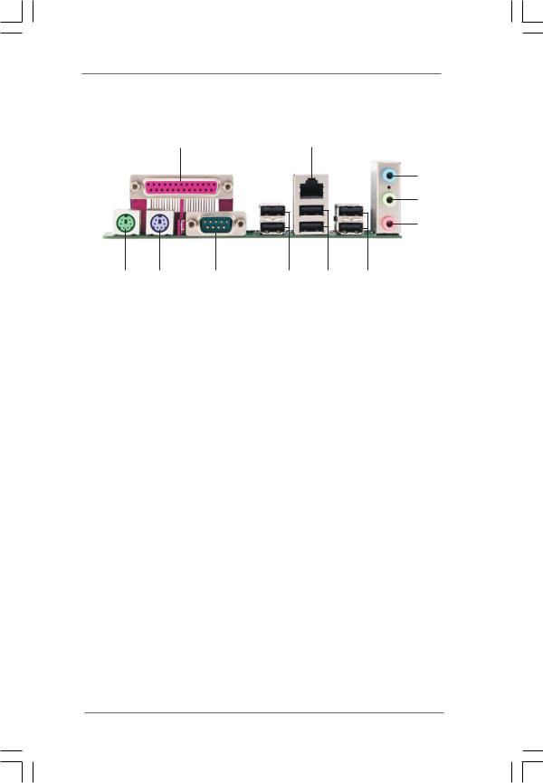
1.4 ASRock I/O PlusTM
1 |
2 |
3
4
5
|
11 |
10 |
9 |
8 |
7 |
6 |
1 |
Parallel Port |
|
7 |
2 x USB 2.0 |
Ports (USB0, USB1) |
|
2 |
RJ-45 Port |
|
8 |
2 x USB 2.0 |
Ports (USB2, USB3) |
|
3 |
Line In (Light Blue) |
|
9 |
Serial Port: COM1 |
||
4 |
Line Out (Lime) |
|
10 |
PS/2 Keyboard Port (Purple) |
||
5 |
Microphone (Pink) |
|
11 |
PS/2 Mouse Port (Green) |
||
6 |
2 x Shared USB 2.0 Ports (USB4, USB5) |
|
|
|
||
9

2. Installation
P4V88-M+ is a Micro ATX form factor (9.6-in x 8.5-in, 24.4 cm x 21.6 cm) motherboard. Before you install the motherboard, study the configuration of your chassis to ensure that the motherboard fits into it.
Pre-installation Precautions
Take note of the following precautions before you install motherboard components or change any motherboard settings.
1.Unplug the power cord from the wall socket before touching any component.
2.To avoid damaging the motherboard components due to static electricity, NEVER place your motherboard directly on the carpet or the like. Also remember to use a grounded wrist strap or touch a safety grounded object before you handle components.
3.Hold components by the edges and do not touch the ICs.
4.Whenever you uninstall any component, place it on a grounded antistatic pad or in the bag that comes with the component.
Before you install or remove any component, ensure that the power is switched off or the power cord is detached from the power supply. Failure to do so may cause severe damage to the motherboard, peripherals, and/or components.
1 0
2.1 CPU Installation
Step 1. Unlock the socket by lifting the lever up to a 90° angle.
Step 2. Position the CPU directly above the socket such that its marked corner matches the base of the socket lever.
Step 3. Carefully insert the CPU into the socket until it fits in place.
The CPU fits only in one correct orientation. DO NOT force the
CPU into the socket to avoid bending of the pins.
Step 4. When the CPU is in place, press it firmly on the socket while you push down the socket lever to secure the CPU. The lever clicks on the side tab to indicate that it is locked.
Lift Lever Up to 90°
STEP 1:
Lift The Socket Lever Up to 90°
CPU Marked Corner |
|
Socket Marked Corner |
|
STEP 2/STEP 3: |
STEP 4: |
Match The CPU Marked Corner |
Push Down And Lock |
to The Socket Marked Corner |
TheSocketLever |
2.2 Installation of CPU Fan and Heatsink
This motherboard adopts 478-pin CPU socket to support Intel® Pentium® 4 / Celeron® CPU. It requires larger heatsink and cooling fan to dissipate heat. You also need to spray thermal grease between the CPU and the heatsink to improve heat dissipation. Make sure that the CPU and the heatsink are securely fastened and in good contact with each other. Then connect the CPU fan to the CPU_FAN connector (CPU_FAN1, see p.8 No. 2). For proper installation, please kindly refer to the instruction manuals of the CPU fan and the heatsink.
1 1
 Loading...