


Copyright Notice:
No part of this installation guide may be reproduced, transcribed, transmitted, or translated in any language, in any form or by any means, except duplication of documentation by the purchaser for backup purpose, without written consent of ASRock Inc.
Products and corporate names appearing in this guide may or may not be registered trademarks or copyrights of their respective companies, and are used only for identification or explanation and to the owners’ benefit, without intent to infringe.
Disclaimer:
Specifications and information contained in this guide are furnished for informational use only and subject to change without notice, and should not be constructed as a commitment by ASRock. ASRock assumes no responsibility for any errors or omissions that may appear in this guide.
With respect to the contents of this guide, ASRock does not provide warranty of any kind, either expressed or implied, including but not limited to the implied warranties or conditions of merchantability or fitness for a particular purpose. In no event shall ASRock, its directors, officers, employees, or agents be liable for any indirect, special, incidental, or consequential damages (including damages for loss of profits, loss of business, loss of data, interruption of business and the like), even if ASRock has been advised of the possibility of such damages arising from any defect or error in the guide or product.
This device complies with Part 15 of the FCC Rules. Operation is subject to the following two conditions:
(1)this device may not cause harmful interference, and
(2)this device must accept any interference received, including interference that may cause undesired operation.
CALIFORNIA, USA ONLY
The Lithium battery adopted on this motherboard contains Perchlorate, a toxic substance controlled in Perchlorate Best Management Practices (BMP) regulations passed by the California Legislature. When you discard the Lithium battery in California, USA, please follow the related regulations in advance.
“Perchlorate Material-special handling may apply, see www.dtsc.ca.gov/hazardouswaste/perchlorate”
ASRock Website: http://www.asrock.com
Published February 2011
Copyright©2011 ASRock INC. All rights reserved.
1
English
ASRock N68-VGS3 UCC / N68-VS3 UCC Motherboard

Motherboard Layout
(N68-VGS3 UCC / N68-VS3 UCC)
English
2
1 |
PS2_USB_PWR1 Jumper |
15 |
Clear CMOS Jumper (CLRCMOS1) |
2 |
CPU Fan Connector (CPU_FAN1) |
16 |
System Panel Header (PANEL1, White) |
3 |
USB_PWR2 Jumper |
17 |
Chassis Speaker Header |
4 |
2 x 240-pin DDR3 DIMM Slots |
|
(SPEAKER 1, White) |
|
(Dual Channel: DDR3_A1, DDR3_B1; Blue) |
18 |
Print Port Header (LPT1, White) |
5 |
CPU Heatsink Retention Module |
19 |
Chassis Fan Connector (CHA_FAN1) |
6 |
Primary IDE Connector (IDE1, Blue) |
20 |
Serial Port Connector (COM1) |
7 |
USB 2.0 Header (USB6_7, Blue) |
21 |
PCI Slot (PCI1) |
8 |
USB 2.0 Header (USB4_5, Blue) |
22 |
PCI Express x16 Slot (PCIE1) |
9 |
SATAII Connector (SATAII_2 (PORT 0.1)) |
23 |
Front Panel Audio Header |
10 |
SATAII Connector (SATAII_4 (PORT 1.1)) |
|
(HD_AUDIO1, Lime) |
11 |
SATAII Connector (SATAII_3 (PORT 1.0)) |
24 |
ATX 12V Power Connector (ATX12V1) |
12 |
SATAII Connector (SATAII_1 (PORT 0.0)) |
25 |
AM3 CPU Socket |
13 |
NVIDIA GeForce 7025 / nForce 630a |
26 |
ATX Power Connector (ATXPWR1) |
14 |
SPI Flash Memory (4Mb) |
|
|
ASRock N68-VGS3 UCC / N68-VS3 UCC Motherboard
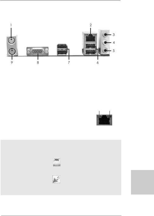
I/O Panel (N68-VGS3 UCC)
1 |
PS/2 Mouse Port (Green) |
6 |
USB 2.0 |
Ports (USB01) |
* 2 |
RJ-45 Port |
7 |
USB 2.0 |
Ports (USB23) |
3 |
Line In (Light Blue) |
8 |
VGA Port |
|
4 |
Front Speaker (Lime) |
9 |
PS/2 Keyboard Port (Purple) |
|
5Microphone (Pink)
*There are two LED next to the LAN port. Please refer to the table below for the LAN port LED
indications.
|
LAN Port LED Indications |
ACT/LINK |
SPEED |
||||
|
LED |
LED |
|||||
Activity/Link LED |
|
|
SPEED LED |
||||
|
|
|
|
||||
Status |
Description |
|
Status |
|
Description |
|
|
Off |
No Activity |
|
Off |
|
10Mbps connection |
|
|
Blinking |
Data Activity |
|
Orange |
|
100Mbps connection |
LAN Port |
|
|
|
|
Green |
|
1Gbps connection |
||
|
|
|
|
|
|
||
To enable Multi-Streaming function, you need to connect a front panel audio cable to the front panel audio header. After restarting your computer, you will find “VIA HD Audio Deck” tool on your system. Please follow below instructions according to the OS you install.
For Windows® XP / XP 64-bit OS: |
|
Please click “VIA HD Audio Deck” icon |
, and click “Speaker”. Then you are allowed to |
select “2 Channel” or “4 Channel”. Click “Power” to save your change.
For Windows® 7 / 7 64-bit / VistaTM / VistaTM 64-bit OS:
Please click “VIA HD Audio Deck” icon |
, and click “Advanced Options” on the left side |
on the bottom. In “Advanced Options” screen, select “Independent Headphone”, and click “OK” to save your change.
3
English
ASRock N68-VGS3 UCC / N68-VS3 UCC Motherboard
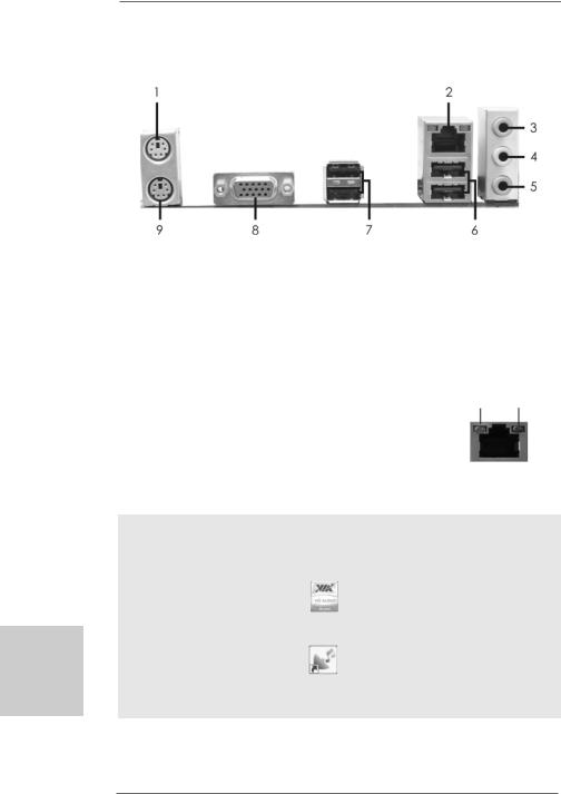
I/O Panel (N68-VS3 UCC)
1 |
PS/2 Mouse Port (Green) |
6 |
USB 2.0 |
Ports (USB01) |
* 2 |
RJ-45 Port |
7 |
USB 2.0 |
Ports (USB23) |
3 |
Line In (Light Blue) |
8 |
VGA Port |
|
4 |
Front Speaker (Lime) |
9 |
PS/2 Keyboard Port (Purple) |
|
5Microphone (Pink)
*There are two LED next to the LAN port. Please refer to the table below for the LAN port LED
indications.
|
LAN Port LED Indications |
ACT/LINK |
SPEED |
||||
|
LED |
LED |
|||||
Activity/Link LED |
|
|
SPEED LED |
||||
|
|
|
|
||||
Status |
Description |
|
Status |
|
Description |
|
|
Off |
No Activity |
|
Off |
|
10Mbps connection |
|
|
Blinking |
Data Activity |
|
Orange |
|
100Mbps connection |
LAN Port |
|
|
|
|
|
|
|
||
English
4
To enable Multi-Streaming function, you need to connect a front panel audio cable to the front panel audio header. After restarting your computer, you will find “VIA HD Audio Deck” tool on your system. Please follow below instructions according to the OS you install.
For Windows® XP / XP 64-bit OS: |
|
Please click “VIA HD Audio Deck” icon |
, and click “Speaker”. Then you are allowed to |
select “2 Channel” or “4 Channel”. Click “Power” to save your change.
For Windows® 7 / 7 64-bit / VistaTM / VistaTM 64-bit OS:
Please click “VIA HD Audio Deck” icon |
, and click “Advanced Options” on the left side |
on the bottom. In “Advanced Options” screen, select “Independent Headphone”, and click “OK” to save your change.
ASRock N68-VGS3 UCC / N68-VS3 UCC Motherboard
1. Introduction
Thank you for purchasing ASRock N68-VGS3 UCC / N68-VS3 UCC motherboard, a reliable motherboard produced under ASRock’s consistently stringent quality control. It delivers excellent performance with robust design conforming to ASRock’s commitment to quality and endurance.
In this manual, chapter 1 and 2 contain introduction of the motherboard and step-by-step guide to the hardware installation. Chapter 3 and 4 contain the configuration guide to BIOS setup and information of the Support CD.
Because the motherboard specifications and the BIOS software might be updated, the content of this manual will be subject to change without notice. In case any modifications of this manual occur, the updated version will be available on ASRock website without further notice. You may find the latest VGA cards and CPU support lists on ASRock website as well. ASRock website http://www.asrock.com
If you require technical support related to this motherboard, please visit our website for specific information about the model you are using. www.asrock.com/support/index.asp
1.1Package Contents
One ASRock N68-VGS3 UCC / N68-VS3 UCC Motherboard (Micro ATX Form Factor: 8.5-in x 7.0-in, 21.6 cm x 17.8 cm)
One ASRock N68-VGS3 UCC / N68-VS3 UCC Quick Installation Guide One ASRock N68-VGS3 UCC / N68-VS3 UCC Support CD
Two Serial ATA (SATA) Data Cables (Optional) One I/O Panel Shield
English
5
ASRock N68-VGS3 UCC / N68-VS3 UCC Motherboard

English
6
1.2Specifications
Platform |
- Micro ATX Form Factor: 8.5-in x 7.0-in, 21.6 cm x 17.8 cm |
CPU |
- Support for AM3 processors: AMD PhenomTM II X6 / X4 / X3 / |
|
X2 (except 920 / 940) / Athlon II X4 / X3 / X2 / Sempron |
|
processors (see CAUTION 1) |
|
- Supports Six-Core CPU |
|
- Supports UCC feature (Unlock CPU Core) (see CAUTION 2) |
|
- Supports AMD’s Cool ‘n’ QuietTM Technology |
|
- FSB 1000 MHz (2.0 GT/s) |
|
- Supports Untied Overclocking Technology (see CAUTION 3) |
|
- Supports Hyper-Transport Technology |
|
|
Chipset |
- NVIDIA® GeForce 7025 / nForce 630a |
Memory |
- Dual Channel DDR3 Memory Technology (see CAUTION 4) |
|
- 2 x DDR3 DIMM slots |
|
- Support DDR3 1600/1333/1066/800 non-ECC, un-buffered |
|
memory (see CAUTION 5) |
|
- Max. capacity of system memory: 8GB (see CAUTION 6) |
Expansion Slot |
- 1 x PCI Express x16 slot |
|
- 1 x PCI slot |
Graphics |
- Integrated NVIDIA® GeForce 7025 graphics |
|
- DX9.0 VGA, Pixel Shader 3.0 |
|
- Max. shared memory 256MB (see CAUTION 7) |
|
- Supports D-Sub with max. resolution up to 1920x1440 |
|
@ 60Hz |
Audio |
- 5.1 CH HD Audio (VIA® VT1705 Audio Codec) |
LAN |
- N68-VGS3 UCC |
|
Realtek Giga PHY RTL8211CL, speed 10/100/1000 Mb/s |
|
- N68-VS3 UCC |
|
Realtek PHY RTL8201EL, speed 10/100 Mb/s |
|
- Supports Wake-On-LAN |
|
|
Rear Panel I/O |
I/O Panel |
|
- 1 x PS/2 Mouse Port |
|
- 1 x PS/2 Keyboard Port |
|
- 1 x VGA Port |
|
- 4 x Ready-to-Use USB 2.0 Ports |
|
- 1 x RJ-45 LAN Port with LED (ACT/LINK LED and SPEED LED) |
|
- HD Audio Jack: Line in / Front Speaker / Microphone |
Connector |
- 4 x Serial ATAII 3.0Gb/s connectors, support RAID (RAID 0, |
|
RAID 1, RAID 0+1, RAID 5, JBOD), NCQ and “Hot Plug” |
|
functions (see CAUTION 8) |
ASRock N68-VGS3 UCC / N68-VS3 UCC Motherboard

|
- 1 x ATA133 IDE connector (supports 2 x IDE devices) |
|
- 1 x Print port header |
|
- 1 x COM port header |
|
- CPU/Chassis FAN connector |
|
- 24 pin ATX power connector |
|
- 4 pin 12V power connector |
|
- Front panel audio header |
|
- 2 x USB 2.0 headers (support 4 USB 2.0 ports) |
BIOS Feature |
- 4Mb AMI BIOS |
|
- AMI Legal BIOS |
|
- Supports “Plug and Play” |
|
- ACPI 1.1 Compliance Wake Up Events |
|
- Supports jumperfree |
|
- SMBIOS 2.3.1 Support |
|
- CPU, VCCM Voltage Multi-adjustment |
Support CD |
- Drivers, Utilities, AntiVirus Software (Trial Version), |
|
ASRock Software Suite (CyberLink DVD Suite - OEM and |
|
Trial; Creative Sound Blaster X-Fi MB - Trial) |
Unique Feature |
- ASRock OC Tuner (see CAUTION 9) |
|
- Intelligent Energy Saver (see CAUTION 10) |
|
- Instant Boot |
|
- ASRock Instant Flash (see CAUTION 11) |
|
- ASRock OC DNA (see CAUTION 12) |
|
- ASRock AIWI (see CAUTION 13) |
|
- ASRock APP Charger (see CAUTION 14) |
|
- SmartView (see CAUTION 15) |
|
- ASRock XFast USB (see CAUTION 16) |
|
- Hybrid Booster: |
|
- CPU Frequency Stepless Control (see CAUTION 17) |
|
- ASRock U-COP (see CAUTION 18) |
|
- Boot Failure Guard (B.F.G.) |
Hardware |
- CPU Temperature Sensing |
Monitor |
- Chassis Temperature Sensing |
|
- CPU Fan Tachometer |
|
- Chassis Fan Tachometer |
|
- CPU Quiet Fan |
|
- Voltage Monitoring: +12V, +5V, +3.3V, Vcore |
|
|
OS |
- Microsoft® Windows® 7 / 7 64-bit / VistaTM / VistaTM 64-bit |
|
/ XP / XP 64-bit compliant |
Certifications |
- FCC, CE, WHQL |
* For detailed product information, please visit our website: http://www.asrock.com
English
7
ASRock N68-VGS3 UCC / N68-VS3 UCC Motherboard

English
8
WARNING
Please realize that there is a certain risk involved with overclocking, including adjusting the setting in the BIOS, applying Untied Overclocking Technology, or using the thirdparty overclocking tools. Overclocking may affect your system stability, or even cause damage to the components and devices of your system. It should be done at your own risk and expense. We are not responsible for possible damage caused by overclocking.
CAUTION!
1.This motherboard supports CPU up to 95W. Please refer to our website for
CPU support list. ASRock website http://www.asrock.com
2.UCC (Unlock CPU Core) feature simplifies AMD CPU activation. As long as a simple switch of the BIOS option “ASRock UCC”, you can unlock the extra CPU core to enjoy an instant performance boost. When UCC feature is enabled, the dual-core or triple-core CPU will boost to the quad-core CPU, and some CPU, including quad-core CPU, can also increase L3 cache size up to 6MB, which means you can enjoy the upgrade CPU performance with a better price. Please be noted that UCC feature is supported with AM3 CPU only, and in addition, not every AM3 CPU can support this function because some CPU’s hidden core may be malfunctioned.
3.This motherboard supports Untied Overclocking Technology. Please read “Untied Overclocking Technology” on page 21 for details.
4.This motherboard supports Dual Channel Memory Technology. Before you implement Dual Channel Memory Technology, make sure to read the installation guide of memory modules on page 13 for proper installation.
5.Whether 1600MHz memory speed is supported depends on the AM3 CPU you adopt. If you want to adopt DDR3 1600 memory module on this motherboard, please refer to the memory support list on our website for the compatible memory modules.
ASRock website http://www.asrock.com
6.Due to the operating system limitation, the actual memory size may be less than 4GB for the reservation for system usage under Windows® 7 / VistaTM / XP. For Windows® OS with 64-bit CPU, there is no such limitation.
7.The maximum shared memory size is defined by the chipset vendor and is subject to change. Please check NVIDIA® website for the latest information.
8.Before installing SATAII hard disk to SATAII connector, please read the “SATAII Hard Disk Setup Guide” on page 24 of “User Manual” in the support CD to adjust your SATAII hard disk drive to SATAII mode. You can also connect SATA hard disk to SATAII connector directly.
9.It is a user-friendly ASRock overclocking tool which allows you to surveil your system by hardware monitor function and overclock your hardware devices to get the best system performance under Windows® environment. Please visit our website for the operation procedures of ASRock OC Tuner. ASRock website: http://www.asrock.com
ASRock N68-VGS3 UCC / N68-VS3 UCC Motherboard

10.Featuring an advanced proprietary hardware and software design, Intelligent Energy Saver is a revolutionary technology that delivers unparalleled power savings. The voltage regulator can reduce the number of output phases to improve efficiency when the CPU cores are idle. In other words, it is able to provide exceptional power saving and improve power efficiency without sacrificing computing performance. To use Intelligent Energy Saver function, please enable Cool ‘n’ Quiet option in the BIOS setup in advance. Please visit our website for the operation procedures of Intelligent Energy Saver.
ASRock website: http://www.asrock.com
11.ASRock Instant Flash is a BIOS flash utility embedded in Flash ROM. This convenient BIOS update tool allows you to update system BIOS without entering operating systems first like MS-DOS or Windows®. With this utility, you can press <F6> key during the POST or press <F2> key to BIOS setup menu to access ASRock Instant Flash. Just launch this tool and save the new BIOS file to your USB flash drive, floppy disk or hard drive, then you can update your BIOS only in a few clicks without preparing an additional floppy diskette or other complicated flash utility. Please be noted that the USB flash drive or hard drive must use FAT32/16/12 file system.
12.The software name itself – OC DNA literally tells you what it is capable of. OC DNA, an exclusive utility developed by ASRock, provides a convenient way for the user to record the OC settings and share with others. It helps you to save your overclocking record under the operating system and simplifies the complicated recording process of overclocking settings. With OC DNA, you can save your OC settings as a profile and share with your friends! Your friends then can load the OC profile to their own system to get the same OC settings as yours! Please be noticed that the OC profile can only be shared and worked on the same motherboard.
13.To experience intuitive motion controlled games is no longer only available at Wii. ASRock AIWI utility introduces a new way of PC gaming operation. ASRock AIWI is the world's first utility to turn your iPhone/iPod touch as a game joystick to control your PC games. All you have to do is just to install the ASRock AIWI utility either from ASRock official website or ASRock software support CD to your motherboard, and also download the free AIWI Lite from App store to your iPhone/iPod touch. Connecting your PC and apple devices via Bluetooth or WiFi networks, then you can start experiencing the exciting motion controlled games. Also, please do not forget to pay attention to ASRock official website regularly, we will continuously provide you the most up-do-date supported games! ASRock website: http://www.asrock.com/Feature/Aiwi/index.asp
English
9
ASRock N68-VGS3 UCC / N68-VS3 UCC Motherboard

14.If you desire a faster, less restricted way of charging your Apple devices, such as iPhone/iPod/iPad Touch, ASRock has prepared a wonderful solution for you - ASRock APP Charger. Simply installing the APP Charger driver, it makes your iPhone charged much quickly from your computer and up to 40% faster than before. ASRock APP Charger allows you to quickly charge many Apple devices simultaneously and even supports continuous charging when your PC enters into Standby mode (S1), Suspend to RAM (S3), hibernation mode (S4) or power off (S5). With APP Charger driver installed, you can easily enjoy the marvelous charging experience than ever.
ASRock website: http://www.asrock.com/Feature/AppCharger/index.asp
15.SmartView, a new function of internet browser, is the smart start page for IE that combines your most visited web sites, your history, your Facebook friends and your real-time newsfeed into an enhanced view for a more personal Internet experience. ASRock motherboards are exclusively equipped with the SmartView utility that helps you keep in touch with friends on-the-go. To use SmartView feature, please make sure your OS version is Windows® 7 / 7 64 bit / VistaTM / VistaTM 64 bit, and your browser version is IE8.
ASRock website: http://www.asrock.com/Feature/SmartView/index.asp
16.ASRock XFast USB can boost USB storage device performance. The performance may depend on the property of the device.
17.Although this motherboard offers stepless control, it is not recommended to perform over-clocking. Frequencies other than the recommended CPU bus frequencies may cause the instability of the system or damage the CPU.
18.While CPU overheat is detected, the system will automatically shutdown. Before you resume the system, please check if the CPU fan on the motherboard functions properly and unplug the power cord, then plug it back again. To improve heat dissipation, remember to spray thermal grease between the CPU and the heatsink when you install the PC system.
English
1 0
ASRock N68-VGS3 UCC / N68-VS3 UCC Motherboard
2. Installation
This is a Micro ATX form factor (8.5-in x 7.0-in, 21.6 cm x 17.8 cm) motherboard. Before you install the motherboard, study the configuration of your chassis to ensure that the motherboard fits into it.
Pre-installation Precautions
Take note of the following precautions before you install motherboard components or change any motherboard settings.
Before you install or remove any component, ensure that the power is switched off or the power cord is detached from the power supply. Failure to do so may cause severe damage to the motherboard, peripherals, and/or components.
1.Unplug the power cord from the wall socket before touching any component.
2.To avoid damaging the motherboard components due to static electricity, NEVER place your motherboard directly on the carpet or the like. Also remember to use a grounded wrist strap or touch a safety grounded object before you handle components.
3.Hold components by the edges and do not touch the ICs.
4.Whenever you uninstall any component, place it on a grounded antistatic pad or in the bag that comes with the component.
5.When placing screws into the screw holes to secure the motherboard to the chassis, please do not over-tighten the screws! Doing so may damage the motherboard.
English
1 1
ASRock N68-VGS3 UCC / N68-VS3 UCC Motherboard
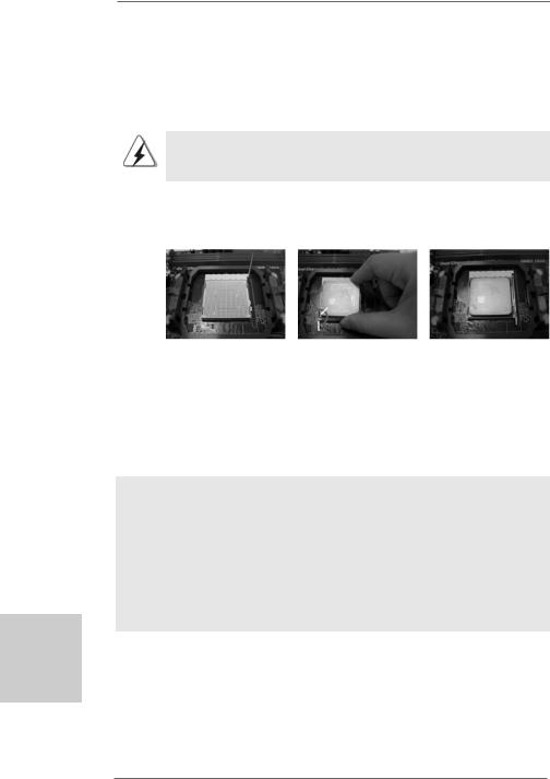
2.1CPU Installation
Step 1. Unlock the socket by lifting the lever up to a 90o angle.
Step 2. Position the CPU directly above the socket such that the CPU corner with the golden triangle matches the socket corner with a small triangle.
Step 3. Carefully insert the CPU into the socket until it fits in place.
The CPU fits only in one correct orientation. DO NOT force the CPU into the socket to avoid bending of the pins.
Step 4. When the CPU is in place, press it firmly on the socket while you push down the socket lever to secure the CPU. The lever clicks on the side tab to indicate that it is locked.
Lever 90° Up |
|
|
|
CPU Golden Triangle |
|
|
Socker Corner Small Triangle |
|
STEP 1: |
STEP 2 / STEP 3: |
STEP 4: |
Lift Up The Socket Lever |
Match The CPU Golden Triangle |
Push Down And Lock |
|
To The Socket Corner Small |
The Socket Lever |
|
Triangle |
|
2.2 Installation of CPU Fan and Heatsink
After you install the CPU into this motherboard, it is necessary to install a larger heatsink and cooling fan to dissipate heat. You also need to spray thermal grease between the CPU and the heatsink to improve heat dissipation. Make sure that the CPU and the heatsink are securely fastened and in good contact with each other. Then connect the CPU fan to the CPU FAN connector (CPU_FAN1, see Page 2, No. 2). For proper installation, please kindly refer to the instruction manuals of the CPU fan and the heatsink.
English
1 2
ASRock N68-VGS3 UCC / N68-VS3 UCC Motherboard
2.3 Installation of Memory Modules (DIMM)
N68-VGS3 UCC / N68-VS3 UCC motherboard provides two 240-pin DDR3 (Double Data Rate 3) DIMM slots, and supports Dual Channel Memory Technology. For dual channel configuration, you always need to install two identical (the same brand, speed, size and chip-type) memory modules in the DDR3 DIMM slots to activate Dual Channel Memory Technology. Otherwise, it will operate at single channel mode.
1.It is not allowed to install a DDR or DDR2 memory module into DDR3 slot;otherwise, this motherboard and DIMM may be damaged.
2.If you install only one memory module or two non-identical memory modules, it is unable to activate the Dual Channel Memory Technology.
Installing a DIMM
Please make sure to disconnect power supply before adding or removing DIMMs or the system components.
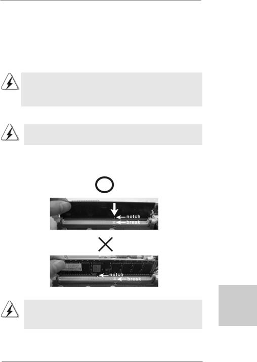
Step 1. Unlock a DIMM slot by pressing the retaining clips outward.
Step 2. Align a DIMM on the slot such that the notch on the DIMM matches the break on the slot.
The DIMM only fits in one correct orientation. It will cause permanent damage to the motherboard and the DIMM if you force the DIMM into the slot at incorrect orientation.
Step 3. Firmly insert the DIMM into the slot until the retaining clips at both ends fully snap back in place and the DIMM is properly seated.
1 3
English
ASRock N68-VGS3 UCC / N68-VS3 UCC Motherboard

2.4 Expansion Slots (PCI and PCI Express Slots)
There are 1 PCI slot and 1 PCI Express slot on this motherboard.
PCI slot: PCI slot is used to install expansion cards that have the 32-bit PCI interface.
PCIE slot:
PCIE1 (PCIE x16 slot) is used for PCI Express cards with x16 lane width graphics cards.
Installing an expansion card
Step 1. Before installing the expansion card, please make sure that the power supply is switched off or the power cord is unplugged. Please read the documentation of the expansion card and make necessary hardware settings for the card before you start the installation.
Step 2. Remove the bracket facing the slot that you intend to use. Keep the screws for later use.
Step 3. Align the card connector with the slot and press firmly until the card is completely seated on the slot.
Step 4. Fasten the card to the chassis with screws.
English
1 4
ASRock N68-VGS3 UCC / N68-VS3 UCC Motherboard

2.5 Easy Multi Monitor Feature
This motherboard supports Multi Monitor upgrade. With the internal onboard VGA |
|
and the external add-on PCI Express VGA card, you can easily enjoy the benefits |
|
of Multi Monitor feature. Please refer to the following steps to set up a multi |
|
monitor environment: |
|
1. Install the NVIDIA® PCI Express VGA card to PCIE1 (PCIE x16 slot). Please refer |
|
to page 14 for proper expansion card installation procedures for details. |
|
2. Connect the D-Sub monitor cable to the VGA/D-Sub port on the I/O panel of this |
|
motherboard. Connect another D-Sub monitor cable to the VGA/D-Sub |
|
connector of the add-on PCI Express VGA card. Connect the DVI-D monitor |
|
cable to the VGA/DVI-D connector of the add-on PCI Express VGA card. |
|
3. Boot your system. Press <F2> or <Del> to enter BIOS setup. Enter “Share |
|
Memory” option to adjust the memory capability to [16MB], [32MB], [64MB], |
|
[128MB] or [256MB] to enable the function of onboard VGA/D-sub. Please make |
|
sure that the value you select is less than the total capability of the system |
|
memory. If you do not adjust the BIOS setup, the default value of “Share |
|
Memory”, [Auto], will disable onboard VGA/D-Sub function when the add-on |
|
VGA card is inserted to this motherboard. |
|
4. Install the onboard VGA driver to your system. If you have installed the |
|
onboard VGA driver already, there is no need to install it again. |
|
5. Set up a multi-monitor display. |
|
For Windows® XP / XP 64-bit OS: |
|
Right click the desktop, choose “Properties”, and select the “Settings” tab so |
|
that you can adjust the parameters of the multi-monitor according to the steps |
|
below. |
|
A. Click the “Identify” button to display a large number on each monitor. |
|
B. Right-click the display icon in the Display Properties dialog that you wish |
|
to be your primary monitor, and then select “Primary”. When you use |
|
multiple monitors with your card, one monitor will always be Primary, and |
|
all additional monitors will be designated as Secondary. |
|
C. Select the display icon identified by the number 2. |
|
D. Click “Extend my Windows desktop onto this monitor”. |
|
E. Right-click the display icon and select “Attached”, if necessary. |
|
F. Set the “Screen Resolution” and “Color Quality” as appropriate for the |
English |
one, two and three. |
|
second monitor. Click “Apply” or “OK” to apply these new values. |
|
G. Repeat steps C through E for the diaplay icon identified by the number |
|
For Windows® 7 / 7 64-bit / VistaTM / VistaTM 64-bit OS: |
|
Right click the desktop, choose “Personalize”, and select the “Display |
|
Settings” tab so that you can adjust the parameters of the multi-monitor |
|
according to the steps below. |
|
A. Click the number ”2” icon. |
1 5 |
|
ASRock N68-VGS3 UCC / N68-VS3 UCC Motherboard
English
B.Click the items “This is my main monitor” and “Extend the desktop onto this monitor”.
C.Click “OK” to save your change.
D.Repeat steps A through C for the display icon identified by the number one, two and three.
6.Use Multi Monitor feature. Click and drag the display icons to positions representing the physical setup of your monitors that you would like to use. The placement of display icons determines how you move items from one monitor to another.
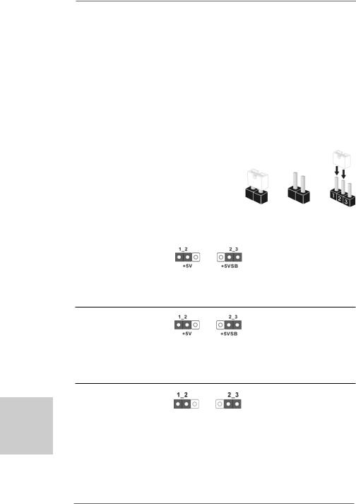
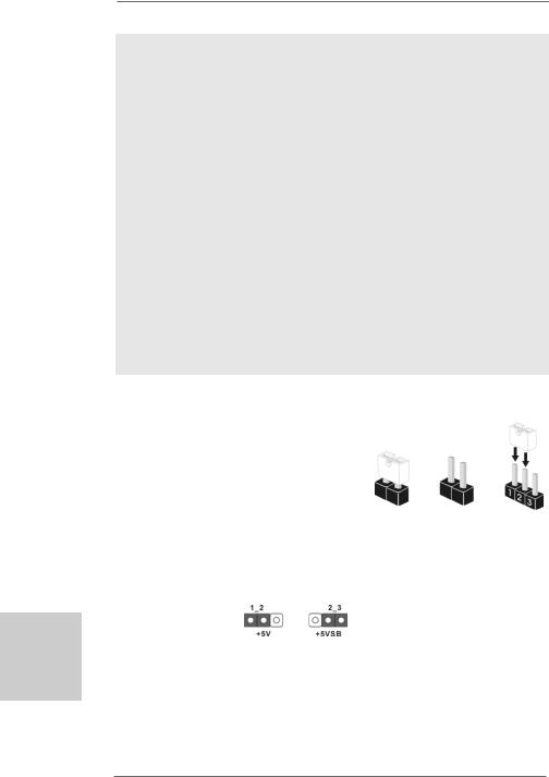
2.6Jumpers Setup
The illustration shows how jumpers are setup. When the jumper cap is placed on pins, the jumper is “Short”. If no jumper cap is placed on pins, the jumper is “Open”. The
illustration shows a 3-pin jumper whose pin1
and pin2 are “Short” when jumper cap is Short Open placed on these 2 pins.
Jumper |
Setting |
PS2_USB_PWR1 |
Short pin2, pin3 to enable |
(see p.2, No. 1) |
+5VSB (standby) for PS/2 or |
|
USB01/23 wake up events. |
Note: To select +5VSB, it requires 2 Amp and higher standby current provided by power supply.
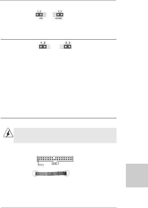
USB_PWR2 |
Short pin2, pin3 to enable |
(see p.2, No. 3) |
+5VSB (standby) for |
|
USB4_5/6_7 wake up |
|
events. |
Note: To select +5VSB, it requires 2 Amp and higher standby current provided by power supply.
Clear CMOS Jumper
(CLRCMOS1)
(see p.2, No. 15) Default Clear CMOS
Note: CLRCMOS1 allows you to clear the data in CMOS. The data in CMOS includes system setup information such as system password, date, time, and system setup parameters. To clear and reset the system parameters to default setup, please turn off the computer and unplug the power cord from the power supply. After waiting for 15 seconds, use a jumper cap to short pin2 and pin3 on CLRCMOS1 for 5 seconds. However, please do not clear the CMOS right
1 6
ASRock N68-VGS3 UCC / N68-VS3 UCC Motherboard
after you update the BIOS. If you need to clear the CMOS when you just finish updating the BIOS, you must boot up the system first, and then shut it down before you do the clear-CMOS action.
2.7 Onboard Headers and Connectors
Onboard headers and connectors are NOT jumpers. Do NOT place jumper caps over these headers and connectors. Placing jumper caps over the headers and connectors will cause permanent damage of the motherboard!
•
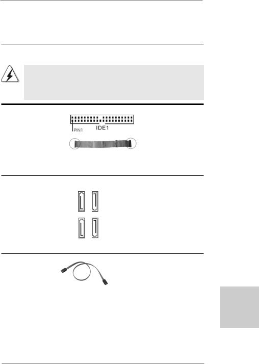
Primary IDE connector (Blue)
(39-pin IDE1, see p.2 No. 6)
connect the blue end |
connect the black end |
to the motherboard |
to the IDE devices |
80-conductor ATA 66/100/133 cable
Note: Please refer to the instruction of your IDE device vendor for the details.
Serial ATAII Connectors
(SATAII_1 (PORT 0.0):
see p.2, No. 12)
(SATAII_2 (PORT 0.1):
see p.2, No. 9)
(SATAII_3 (PORT 1.0): see p.2, No. 11) (SATAII_4 (PORT 1.1): see p.2, No. 10)
Serial ATA (SATA) Data Cable
(Optional)
SATAII 2 |
(PORT 0.1) |
SATAII 4 |
(PORT 1.1) |
SATAII 1 |
(PORT 0.0) |
SATAII 3 |
(PORT 1.0) |
These four Serial ATAII (SATAII) connectors support SATAII
or SATA hard disk for internal storage devices. The current SATAII interface allows up to 3.0 Gb/s data transfer rate.
Either end of the SATA data cable can be connected to the SATA / SATAII hard disk or the SATAII connector on the motherboard.
English
1 7
ASRock N68-VGS3 UCC / N68-VS3 UCC Motherboard
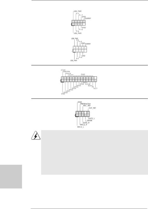
USB 2.0 Headers |
Besides four default USB 2.0 |
(9-pin USB6_7) |
ports on the I/O panel, there are |
(see p.2 No. 7) |
two USB 2.0 headers on this |
|
motherboard. Each USB 2.0 |
|
header can support two USB |
|
2.0 ports. |
(9-pin USB4_5) |
|
(see p.2 No. 8) |
|
Print Port Header |
This is an interface for print |
(25-pin LPT1) |
port cable that allows |
(see p.2 No. 18) |
convenient connection of printer |
|
devices. |
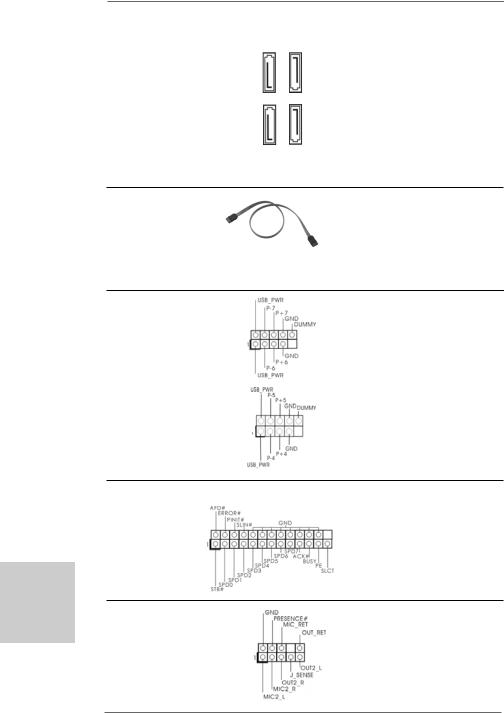
Front Panel Audio Header |
This is an interface for the front |
(9-pin HD_AUDIO1) |
panel audio cable that allows |
(see p.2, No. 23) |
convenient connection and |
|
control of audio devices. |
English
1 8
1.High Definition Audio supports Jack Sensing, but the panel wire on the chassis must support HDA to function correctly. Please follow the
instruction in our manual and chassis manual to install your system.
2.If you use AC’97 audio panel, please install it to the front panel audio header as below:
A.Connect Mic_IN (MIC) to MIC2_L.
B.Connect Audio_R (RIN) to OUT2_R and Audio_L (LIN) to OUT2_L.
C.Connect Ground (GND) to Ground (GND).
D.MIC_RET and OUT_RET are for HD audio panel only. You don’t need to connect them for AC’97 audio panel.
ASRock N68-VGS3 UCC / N68-VS3 UCC Motherboard
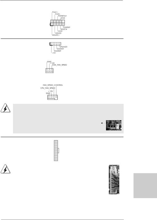
System Panel Header |
This header accommodates |
(9-pin PANEL1) |
several system front panel |
(see p.2 No. 16) |
functions. |
Chassis Speaker Header |
|
|
Please connect the chassis |
(4-pin SPEAKER 1) |
|
|
speaker to this header. |
(see p.2 No. 17) |
|
|
|
|
|
|
|
Chassis Fan Connector |
|
|
Please connect a chassis fan |
(3-pin CHA_FAN1) |
|
|
cable to this connector and |
(see p.2 No. 19) |
|
|
match the black wire to the |
|
|
|
ground pin. |
|
|
|
|
CPU Fan Connector |
|
|
Please connect the CPU fan |
(4-pin CPU_FAN1) |
|
|
cable to this connector and |
(see p.2 No. 2) |
|
|
match the black wire to the |
1 |
2 |
3 |
ground pin. |
4 |
Though this motherboard provides 4-Pin CPU fan (Quiet Fan) support, the 3-Pin CPU fan still can work successfully even without the fan speed control function. If you plan to connect the 3-Pin CPU fan to the CPU fan connector on this
motherboard, please connect it to Pin 1-3.
Pin 1-3 Connected
3-Pin Fan Installation
ATX Power Connector |
12 |
24 |
Please connect an ATX power |
|
|
(24-pin ATXPWR1) |
|
|
supply to this connector. |
|
|
(see p.2 No. 26) |
|
|
|
|
|
|
|
1 |
13 |
|
|
|
|
|
|||
|
Though this motherboard provides 24-pin ATX power connector, 12 |
24 |
|||
|
it can still work if you adopt a traditional 20-pin ATX power supply. |
|
|||
|
To use the 20-pin ATX power supply, please plug your power |
|
|||
|
supply along with Pin 1 and Pin 13. |
|
|
||
|
|
|
20-Pin ATX Power Supply Installation |
13 |
|
|
|
|
|
1 |
|
|
|
|
|
|
|
1 9
English
ASRock N68-VGS3 UCC / N68-VS3 UCC Motherboard
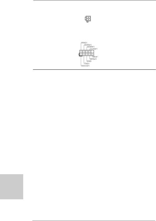
ATX 12V Power Connector |
Please note that it is necessary |
(4-pin ATX12V1) |
to connect a power supply with |
(see p.2 No. 10) |
ATX 12V plug to this connector. |
|
Failing to do so will cause power |
|
up failure. |
|
|
Serial port Header |
This COM1 header supports a |
(9-pin COM1) |
serial port module. |
(see p.2 No.20) |
|
English
2.8 Driver Installation Guide
To install the drivers to your system, please insert the support CD to your optical drive first. Then, the drivers compatible to your system can be auto-detected and listed on the support CD driver page. Please follow the order from up to bottom side to install those required drivers. Therefore, the drivers you install can work properly.
2.9Installing Windows® 7 / 7 64-bit / VistaTM /
VistaTM 64-bit / XP / XP 64-bit Without RAID Functions
If you just want to install Windows® 7 / 7 64-bit / VistaTM / VistaTM 64-bit / XP / XP 64bit on your SATA / SATAII HDDs without RAID functions, you don’t have to make a SATA / SATAII driver diskette. Besides, there is no need for you to change the BIOS setting. You can start to install Windows® 7 / 7 64-bit / VistaTM / VistaTM 64-bit / XP / XP 64-bit on your system directly.
2.10 Installing Windows® 7 / 7 64-bit / VistaTM / VistaTM 64-bit With RAID Functions
If you want to install Windows® 7 / 7 64-bit / VistaTM / VistaTM 64-bit on your SATA / SATAII HDDs with RAID functions, please refer to the document at the following path in the Support CD for detailed procedures:
..\ RAID Installation Guide
2 0
ASRock N68-VGS3 UCC / N68-VS3 UCC Motherboard
2.11 Untied Overclocking Technology
This motherboard supports Untied Overclocking Technology, which means during overclocking, FSB enjoys better margin due to fixed PCI / PCIE buses. Before you enable Untied Overclocking function, please enter “Overclock Mode” option of BIOS setup to set the selection from [Auto] to [CPU, PCIE, Async.]. Therefore, CPU FSB is untied during overclocking, but PCI / PCIE buses are in the fixed mode so that FSB can operate under a more stable overclocking environment.
Please refer to the warning on page 8 for the possible overclocking risk before you apply Untied Overclocking Technology.
3. BIOS Information
The Flash Memory on the motherboard stores BIOS Setup Utility. When you start up the computer, please press <F2> during the Power-On-Self-Test (POST) to enter BIOS Setup utility; otherwise, POST continues with its test routines. If you wish to enter BIOS Setup after POST, please restart the system by pressing <Ctl> + <Alt> + <Delete>, or pressing the reset button on the system chassis. The BIOS Setup program is designed to be user-friendly. It is a menu-driven program, which allows you to scroll through its various sub-menus and to select among the predetermined choices. For the detailed information about BIOS Setup, please refer to the User Manual (PDF file) contained in the Support CD.
4. Software Support CD information
This motherboard supports various Microsoft® Windows® operating systems: 7 /
7 64-bit / VistaTM / VistaTM 64-bit / XP / XP 64-bit. The Support CD that came with the motherboard contains necessary drivers and useful utilities that will enhance motherboard features. To begin using the Support CD, insert the CD into your CDROM drive. It will display the Main Menu automatically if “AUTORUN” is enabled in your computer. If the Main Menu does not appear automatically, locate and doubleclick on the file “ASSETUP.EXE” from the “BIN” folder in the Support CD to display the menus.
English
2 1
ASRock N68-VGS3 UCC / N68-VS3 UCC Motherboard

1. Einführung
Wir danken Ihnen für den Kauf des ASRock N68-VGS3 UCC / N68-VS3 UCC Motherboard, ein zuverlässiges Produkt, welches unter den ständigen, strengen Qualitätskontrollen von ASRock gefertigt wurde. Es bietet Ihnen exzellente Leistung und robustes Design, gemäß der Verpflichtung von ASRock zu Qualität und Halbarkeit. Diese Schnellinstallationsanleitung führt in das Motherboard und die schrittweise Installation ein. Details über das Motherboard finden Sie in der Bedienungsanleitung auf der Support-CD.
Da sich Motherboard-Spezifikationen und BIOS-Software verändern können, kann der Inhalt dieses Handbuches ebenfalls jederzeit geändert werden. Für den Fall, dass sich Änderungen an diesem Handbuch ergeben, wird eine neue Version auf der ASRock-Website, ohne weitere Ankündigung, verfügbar sein. Die neuesten Grafikkarten und unterstützten CPUs sind auch auf der ASRock-Website aufgelistet.
ASRock-Website: http://www.asrock.com
Wenn Sie technische Unterstützung zu Ihrem Motherboard oder spezifische Informationen zu Ihrem Modell benötigen, besuchen Sie bitte unsere Webseite:
www.asrock.com/support/index.asp
1.1 Kartoninhalt
ASRock N68-VGS3 UCC / N68-VS3 UCC Motherboard
(Micro ATX-Formfaktor: 21.6 cm x 17.8 cm; 8.5 Zoll x 7.0 Zoll) ASRock N68-VGS3 UCC / N68-VS3 UCC Schnellinstallationsanleitung ASRock N68-VGS3 UCC / N68-VS3 UCC Support-CD
Zwei Seriell-ATA- (SATA) Datenkabel (Option) Ein I/OShield
Deutsch
2 2
ASRock N68-VGS3 UCC / N68-VS3 UCC Motherboard

1.2Spezifikationen
Plattform |
- Micro ATX-Formfaktor: 21.6 cm x 17.8 cm; 8.5 Zoll x 7.0 Zoll |
CPU |
- Unterstützung von Socket AM3-Prozessoren: AMD PhenomTM |
|
II X6 / X4 / X3 / X2 (außer 920 / 940) / Athlon X4 / X3 / X2 / |
|
Sempron-Prozessor (siehe VORSICHT 1) |
|
- Sechs-Kern-CPU-bereit |
|
- Unterstützt UCC (Unlock CPU Core) (siehe VORSICHT 2) |
|
- Unterstützt Cool ‘n’ QuietTM-Technologie von AMD |
|
- FSB 1000 MHz (2.0 GT/s) |
|
- Unterstützt Untied-Übertaktungstechnologie |
|
(siehe VORSICHT 3) |
|
- Unterstützt Hyper-Transport-Technologie |
Chipsatz |
- NVIDIA® GeForce 7025 / nForce 630a |
Speicher |
- Unterstützung von Dual-Kanal-Speichertechnologie |
|
(siehe VORSICHT 4) |
|
- 2 x Steckplätze für DDR3 |
|
- Unterstützt DDR3 1600/1333/1066/800 non-ECC, |
|
ungepufferter Speicher (siehe VORSICHT 5) |
|
- Max. Kapazität des Systemspeichers: 8GB |
|
(siehe VORSICHT 6) |
Erweiterungs- |
- 1 x PCI Express x16-Steckplätze |
steckplätze |
- 1 x PCI -Steckplätze |
|
|
Onboard-VGA |
- Integrierter NVIDIA® GeForce 7025 Grafikchip |
|
- DX9.0 VGA, Pixel Shader 3.0 |
|
- Maximal gemeinsam genutzter Speicher 256 MB |
|
(siehe VORSICHT 7) |
|
- Unterstützt D-Sub mit einer maximalen Auflösung von |
|
1920 x 1440 bei 60 Hz |
|
|
Audio |
- 5.1 CH HD Audio (VIA® VT1705 Audio Codec) |
LAN |
- N68-VGS3 UCC |
|
Realtek Giga PHY RTL8211CL, speed 10/100/1000 Mb/s |
|
- N68-VS3 UCC |
|
Realtek PHY RTL8201EL, speed 10/100 Mb/s |
|
- Unterstützt Wake-On-LAN |
|
|
E/A-Anschlüsse |
I/O Panel |
an der |
- 1 x PS/2-Mausanschluss |
Rückseite |
- 1 x PS/2-Tastaturanschluss |
|
- 1 x VGA port |
|
- 4 x Standard-USB 2.0-Anschlüsse |
|
- 1 x RJ-45 LAN Port mit LED (ACT/LINK LED und SPEED LED) |
Deutsch
2 3
ASRock N68-VGS3 UCC / N68-VS3 UCC Motherboard

|
|
|
|
- HD Audiobuchse: Audioeingang / Lautsprecher vorne / |
|
|
|
|
Mikrofon |
|
|
|
Anschlüsse |
- 4 x SATAII-Anschlüsse, unterstützt bis 3.0 Gb/s |
|
|
|
|
Datenübertragungsrate, unterstützt RAID (RAID 0, RAID 1, |
|
|
|
|
RAID 0+1, RAID 5, JBOD), NCQ und “Hot Plug” Funktionen |
|
|
|
|
(siehe VORSICHT 8) |
|
|
|
|
- 1 x ATA133 IDE-Anschlüsse (Unterstützt bis 2 IDE-Geräte) |
|
|
|
|
- 1 x Druckerport-Anschlussleiste |
|
|
|
|
- 1 x COM-Anschluss-Header |
|
|
|
|
- CPU/Gehäuse-Lüfteranschluss |
|
|
|
|
- 24-pinATX-Netz-Header |
|
|
|
|
- 4-pin anschluss für 12V-ATX-Netzteil |
|
|
|
|
- Anschluss für Audio auf der Gehäusevorderseite |
|
|
|
|
- 2 x USB 2.0-Anschlüsse (Unterstützung 4 zusätzlicher |
|
|
|
|
USB 2.0-Anschlüsse) |
|
|
|
BIOS |
- 4Mb AMI BIOS |
|
|
|
|
- AMI legal BIOS mit Unterstützung für “Plug and Play” |
|
|
|
|
- ACPI 1.1-Weckfunktionen |
|
|
|
|
- JumperFree-Modus |
|
|
|
|
- SMBIOS 2.3.1 |
|
|
|
|
- CPU, VCCM Stromspannung Multianpassung |
|
|
|
Support-CD |
- Treiber, Dienstprogramme, Antivirussoftware |
|
|
|
|
(Probeversion), ASRock-Software-Suite (CyberLink |
|
|
|
|
DVD Suite und Creative Sound Blaster X-Fi MB) (OEMund |
|
|
|
|
Testversion) |
|
|
|
Einzigartige |
- ASRock OC Tuner (siehe VORSICHT 9) |
|
|
|
Eigenschaft |
- Intelligent Energy Saver (Intelligente Energiesparfunktion) |
|
|
|
|
(siehe VORSICHT 10) |
|
|
|
|
- Sofortstart |
|
|
|
|
- ASRock Instant Flash (siehe VORSICHT 11) |
|
|
|
|
- ASRock OC DNA (siehe VORSICHT 12) |
|
|
|
|
- ASRock AIWI (siehe VORSICHT 13) |
|
|
|
|
- ASRock APP Charger (siehe VORSICHT 14) |
|
|
|
|
- SmartView (siehe VORSICHT 15) |
Deutsch |
|
|
|
|
|
|
- ASRock XFast USB (siehe VORSICHT 16) |
||
|
|
|
|
|
|
|
|
|
- Hybrid Booster: |
|
|
|
|
- Schrittloser CPU-Frequenz-Kontrolle |
|
|
|
|
(siehe VORSICHT 17) |
|
|
|
|
- ASRock U-COP (siehe VORSICHT 18) |
|
|
|
|
- Boot Failure Guard (B.F.G. – Systemstartfehlerschutz) |
|
|
|
Hardware Monitor |
- CPU-Temperatursensor |
|
|
|
|
- Motherboardtemperaturerkennung |
2 4 |
|
|
|
|
|
|
|
||
ASRock N68-VGS3 UCC / N68-VS3 UCC Motherboard

|
- Drehzahlmessung für CPU-Lüfter |
|
- Drehzahlmessung für Gehäuselüfter |
|
- CPU-Lüftergeräuschdämpfung |
|
- Spannungsüberwachung: +12V, +5V, +3.3V, Vcore |
|
|
Betriebssysteme |
- Unterstützt Microsoft® Windows® 7 / 7 64-Bit / VistaTM / |
|
VistaTM 64-Bit / XP / XP 64-Bit |
Zertifizierungen |
- FCC, CE, WHQL |
* Für die ausführliche Produktinformation, besuchen Sie bitte unsere Website: http://www.asrock.com
WARNUNG
Beachten Sie bitte, dass Overclocking, einschließlich der Einstellung im BIOS, Anwenden der Untied Overclocking-Technologie oder Verwenden von Overclocking-Werkzeugen von Dritten, mit einem gewissen Risiko behaftet ist. Overclocking kann sich nachteilig auf die Stabilität Ihres Systems auswirken oder sogar Komponenten und Geräte Ihres Systems beschädigen. Es geschieht dann auf eigene Gefahr und auf Ihre Kosten. Wir übernehmen keine Verantwortung für mögliche Schäden, die aufgrund von Overclocking verursacht wurden.
VORSICHT!
1.Dieses Motherboard unterstützt CPUs bis 95W. Auf unserer Website finden Sie eine Liste mit unterstützten CPUs.
ASRock-Internetseite: http://www.asrock.com
2.Die UCC-Funktion (Unlock CPU Core; zu Deutsch: CPU-Kern freigeben) vereinfacht die AMD-CPU-Aktivierung. Zur Freigabe des zusätzlichen CPUKerns müssen Sie lediglich die BIOS-Option „ASRock UCC“ umschalten – schon profitieren Sie von einem Leistungsschub. Wenn die UCC-Funktion aktiviert ist, rüstet die Dual-Core- oder Triple-Core-CPU auf eine Quad- Core-CPU auf – einige CPUs (inklusive Quad-Core) können zudem die L3- Cache-Größe auf bis zu 6 MB anheben; das bedeutet verbesserte CPULeistung zu einem geringeren Preis. Bitte beachten Sie, dass die UCCFunktion nur bei AM3-CPUs einsetzbar ist; die Unterstützung besteht jedoch aufgrund möglicher Fehlfunktionen des verborgenen Kerns einiger CPUs auch nicht zwangsläufig bei jeder AM3-CPU.
3.Dieses Motherboard unterstützt die Untied-Übertaktungstechnologie. Unter “Entkoppelte Übertaktungstechnologie” auf Seite 21 finden Sie detaillierte Informationen.
4.Dieses Motherboard unterstützt Dual-Kanal-Speichertechnologie. Vor Implementierung der Dual-Kanal-Speichertechnologie müssen Sie die Installationsanleitung für die Speichermodule auf Seite 13 zwecks richtiger Installation gelesen haben.
5.Ob die Speichergeschwindigkeit 1600 MHz unterstützt wird, hängt von der von Ihnen eingesetzten AM3-CPU ab. Schauen Sie bitte auf unseren Internetseiten in der Liste mit unterstützten Speichermodulen nach, wenn Sie DDR3 1600-Speichermodule einsetzen möchten.
ASRock-Internetseite: http://www.asrock.com
2 5
Deutsch
ASRock N68-VGS3 UCC / N68-VS3 UCC Motherboard

Deutsch
2 6
6.Durch Betriebssystem-Einschränkungen kann die tatsächliche Speichergröße weniger als 4 GB betragen, da unter Windows® 7 / Vista™ / XP etwas Speicher zur Nutzung durch das System reserviert wird. Unter Windows® OS mit 64-Bit-CPU besteht diese Einschränkung nicht.
7.Die Maximalspeichergröße ist von den Chipshändler definiert und umgetauscht. Bitte überprüfen Sie NVIDIA® website für die neuliche Information.
8.Vor Installation der SATAII-Festplatte an den SATAII-Anschluss lesen Sie bitte “Setup-Anleitung für SATAII-Festplatte” auf Seite 24 der “Bedienungsanleitung” auf der Support-CD, um Ihre SATAII-Festplatte dem SATAII-Modus anzugleichen. Sie können die SATA-Festplatte auch direkt mit dem SATAII-Anschluss verbinden.
9.Es ist ein benutzerfreundlicher ASRock Übertaktenswerkzeug, das erlaubt, dass Sie Ihr System durch den Hardware-Monitor Funktion zu überblicken und Ihre Hardware-Geräte übertakten, um die beste Systemleistung unter der Windows® Umgebung zu erreichen. Besuchen Sie bitte unsere Website für die Operationsverfahren von ASRock OC Tuner. ASRock-Website: http://www.asrock.com
10.Mit einer eigenen, modernen Hardware und speziellem Softwaredesign, bietet der Intelligent Energy Saver eine revolutionäre Technologie zur bisher unerreichten Energieeinsparung. Ein Spannungsregler kann die Anzahl von Ausgangsphasen zur Effektivitätsverbessserung reduzieren, wenn sich die CPU im Leerlauf befindet. Mit anderen Worten: Sie genießen außergewöhnliche Energieeinsparung und verbesserten Wirkungsgrad ohne Leistungseinschränkungen. Wenn Sie die Intelligent Energy Saver-Funktion nutzen möchten, aktivieren Sie zuvor die „Cool ‘n’ Quiet“-Option im BIOS. Weitere Bedienungshinweise zum Intelligent Energy Saver finden Sie auf unseren Internetseiten. ASRock-Internetseite: http://www.asrock.com
11.ASRock Instant Flash ist ein im Flash-ROM eingebettetes BIOS-Flash- Programm. Mithilfe dieses praktischen BIOSAktualisierungswerkzeugs können Sie das System-BIOS aktualisieren, ohne dafür zuerst Betriebssysteme wie MS-DOS oder Windows® aufrufen zu müssen. Mit diesem Programm bekommen Sie durch Drücken der <F6>-Taste während des POST-Vorgangs oder durch Drücken der <F2>-Taste im BIOS-Setup-Menü Zugang zu ASRock Instant Flash. Sie brauchen dieses Werkzeug einfach nur zu starten und die neue BIOS-Datei auf Ihrem USB-Flash-Laufwerk, Diskettenlaufwerk oder der Festplatte zu speichern, und schon können Sie Ihr BIOS mit nur wenigen Klickvorgängen ohne Bereitstellung einer zusätzlichen Diskette oder eines anderen komplizierten Flash-Programms aktualisieren. Achten Sie darauf, dass das USB-Flash-Laufwerk oder die Festplatte das Dateisystem FAT32/16/12 benutzen muss.
12.Allein der Name – OC DNA* – beschreibt es wörtlich, was die Software zu leisten vermag. OC DNA ist ein von ASRock exklusiv entwickeltes Dienstprogramm, das Nutzern eine bequeme Möglichkeit bietet,
ASRock N68-VGS3 UCC / N68-VS3 UCC Motherboard

Übertaktungseinstellungen aufzuzeichnen und sie Anderen mitzuteilen. Es hilft Ihnen, Ihre Übertaktungsaufzeichnung im Betriebssystem zu speichern und vereinfacht den komplizierten Aufzeichnungsvorgang von Übertaktungseinstellungen. Mit OC DNA können Sie Ihre Übertaktungseinstellungen als Profil abspeichern und Ihren Freunden zugänglich machen! Ihre Freunde können dann das Übertaktungsprofil auf ihren eigenen Systemen laden, um dieselben Übertaktungseinstellungen. Mit OC DNA können Sie Ihre Übertaktungseinstellungen als Profil abspeichern und Ihren Freunden zugänglich machen! Ihre Freunde können dann das Übertaktungsprofil auf ihren eigenen Systemen laden, um dieselben Übertaktungseinstellungen wie Sie zu erhalten! Beachten Sie bitte, dass das Übertaktungsprofil nur bei einem identischen Motherboard gemeinsam genutzt und funktionsfähig gemacht werden kann. Übertaktungseinstellungen wie Sie zu erhalten! Beachten Sie bitte, dass das Übertaktungsprofil nur bei einem identischen Motherboard gemeinsam genutzt und funktionsfähig gemacht werden kann.
13.Das Erlebnis intuitiver, bewegungsgesteuerter Spiele ist nicht mehr nur noch an der Wii möglich. Das ASRock AIWI-Dienstprogramm führt eine neue Möglichkeit der PC-Spielsteuerung ein. ASRock AIWI ist das weltweit erste Dienstprogramm, mit dem Sie Ihr iPhone/iPod touch in einen Joystick zur Steuerung Ihrer PC-Spiele verwandeln können. Sie müssen lediglich das ASRock AIWI-Dienstprogramm – entweder von der offiziellen ASRock-Webseite oder der ASRock-Software-CD Ihres Motherboards – installieren sowie das kostenlose AIWI Lite vom App Store auf Ihr iPhone/iPod touch herunterladen. Verbinden Sie Ihren PC und das Apple-Gerät via Bluetooth oder Wi-Fi-Netzwerk – schon können Sie die bewegungsgesteuerten Spiele genießen. Bitte denken Sie außerdem daran, regelmäßig einen Blick auf die offizielle ASRockWebseite zu werfen; wir bieten stets topaktuelle Informationen über die unterstützten Spiele!
ASRock-Webseite: http://www.asrock.com/Feature/Aiwi/index.asp
14.Wenn Sie nach einer schnelleren, weniger eingeschränkten Möglichkeit zur Aufladung Ihrer Apple-Geräte (z. B. iPhone/iPad/iPod touch) suchen, bietet ASRock Ihnen eine wunderbare Lösung – den ASRock APP Charger. Installieren Sie einfach den ASRock APP Charger-Treiber; dadurch lädt sich Ihr iPhone wesentlich schneller über einen Computer auf – genaugenommen bis zu 40 % schneller als zuvor. Der ASRock APP Charger ermöglicht Ihnen die schnelle Aufladung mehrerer AppleGeräte gleichzeitig; der Ladevorgang wird sogar dann fortgesetzt, wenn der PC den Ruhezustand (S1), Suspend to RAM-Modus (S3) oder Tiefschlafmodus (S4) aufruft oder ausgeschaltet wird (S5). Nach der Installation des APP Charger-Treibers können Sie im Handumdrehen das großartigste Ladeerlebnis überhaupt genießen. ASRock-Webseite: http:// www.asrock.com/Feature/AppCharger/index.asp
15.SmartView, eine neue Internetbrowserfunktion, ist eine intelligente IEStartseite, die meist besuchte Internetseiten, Ihren Browserverlauf,
Deutsch
2 7
ASRock N68-VGS3 UCC / N68-VS3 UCC Motherboard
Deutsch
Facebook-Freunde und Nachrichten in Echtzeit miteinander kombiniert: In einer speziellen Ansicht, die das Internet noch angenehmer und aufregender macht. ASRock-Motherboards werden exklusiv mit der Smart- View-Software geliefert, die auch dafur sorgt, dass Sie immer mit Ihren Freunden in Verbindung bleiben. Die SmartView-Funktionen konnen Sie mit den Windows®-Betriebssystemen 7 / 7, 64 Bit / VistaTM / VistaTM 64 Bit und dem Internet Explorer ab Version 8 nutzen. ASRock-Website: http://www.asrock.com/Feature/SmartView/index.asp
16.ASRocks XFast USB dient der Steigerung der Leistungsfähigkeit Ihrer USB-Speichergeräte. Die Leistung kann je nach Eigenschaften des Gerätes variieren.
17.Obwohl dieses Motherboard stufenlose Steuerung bietet, wird Overclocking nicht empfohlen. Frequenzen, die von den empfohlenen CPU-Busfrequenzen abweichen, können Instabilität des Systems verursachen oder die CPU beschädigen.
18.Wird eine Überhitzung der CPU registriert, führt das System einen automatischen Shutdown durch. Bevor Sie das System neu starten, prüfen Sie bitte, ob der CPU-Lüfter am Motherboard richtig funktioniert, und stecken Sie bitte den Stromkabelstecker aus und dann wieder ein. Um die Wärmeableitung zu verbessern, bitte nicht vergessen, etwas Wärmeleitpaste zwischen CPU und Kühlkörper zu sprühen.
1.3Einstellung der Jumper
Die Abbildung verdeutlicht, wie Jumper gesetzt werden. Werden Pins durch Jumperkappen verdeckt, ist der Jumper “gebrückt”. Werden keine Pins durch Jumperkappen verdeckt, ist der Jumper
“offen”. Die Abbildung zeigt einen 3-Pin
Gebrückt Offen
Jumper dessen Pin1 und Pin2 “gebrückt” sind, bzw. es befindet sich eine Jumper-Kappe auf diesen beiden Pins.
Jumper |
Einstellun |
PS2_USB_PWR1 |
Überbrücken Sie Pin2, Pin3, um |
(siehe S.2, No. 1) |
+5VSB (Standby) zu setzen |
|
und die PS/2 oder USB01/23- |
|
Weckfunktionen zu aktivieren. |
Hinweis: Um +5VSB nutzen zu können, muss das Netzteil auf dieser Leitung 2A oder mehr leisten können.
2 8
ASRock N68-VGS3 UCC / N68-VS3 UCC Motherboard
USB_PWR2 |
Überbrücken Sie Pin2, Pin3, um |
(siehe S.2, No. 3) |
+5VSB (Standby) zu setzen |
|
und die USB4_5/6_7- |
|
Weckfunktionen zu aktivieren. |
Hinweis: Um +5VSB nutzen zu können, muss das Netzteil auf dieser Leitung 2A oder mehr leisten können.
CMOS löschen
(CLRCMOS1, 3-Pin jumper) |
|
|
(siehe S.2, No. 15) |
Default- |
CMOS |
|
Einstellung |
löschen |
Hinweis: CLRCMOS1 erlaubt Ihnen das Löschen der CMOS-Daten. Diese beinhalten das System-Passwort, Datum, Zeit und die verschiedenen BIOS-Parameter. Um die Systemparameter zu löschen und auf die Werkseinstellung zurückzusetzen, schalten Sie bitte den Computer ab und entfernen das Stromkabel. Benutzen Sie eine Jumperkappe, um die Pin 2 und Pin 3 an CLRCMOS1 für 5 Sekunden kurzzuschließen. Bitte vergessen Sie nicht, den Jumper wieder zu entfernen, nachdem das CMOS gelöscht wurde. Bitte vergessen Sie nicht, den Jumper wieder zu entfernen, nachdem das CMOS gelöscht wurde. Wenn Sie den CMOSInhalt gleich nach dem Aktualisieren des BIOS löschen müssen, müssen Sie zuerst das System starten und dann wieder ausschalten, bevor Sie den CMOS-Inhalt löschen.
1.4 Anschlüsse
Anschlussleisten sind KEINE Jumper. Setzen Sie KEINE Jumperkappen auf die Pins der Anschlussleisten. Wenn Sie die Jumperkappen auf die Anschlüsse setzen, wird das Motherboard permanent beschädigt!
Anschluss |
Beschreibung |
Primärer IDE-Anschluss (blau) |
|
(39-pin IDE1, siehe S.2, No. 6) |
|
Blauer Anschluss |
Schwarzer Anschluss |
zum Motherboard |
zur Festplatte |
|
80-adriges ATA 66/100/133 Kabel |
Hinweis: Details entnehmen Sie bitte den Anweisungen Ihres IDE-Gerätehändlers.
2 9
Deutsch
ASRock N68-VGS3 UCC / N68-VS3 UCC Motherboard
Seriell-ATAII-Anschlüsse
(SATAII_1 (PORT 0.0): |
SATAII2 |
(PORT0.1) |
|
(SATAII_2 (PORT 0.1): |
|||
siehe S.2, No. 12) |
|
|
|
siehe S.2, No. 9) |
|
(PORT0.0) |
|
(SATAII_3 (PORT 1.0): |
SATAII1 |
||
siehe S.2,No. 11) |
|||
|
|
||
(SATAII_4 (PORT 1.1): |
|
|
|
siehe S.2, No. 10) |
|
|
|
Serial ATA- (SATA-) |
|
|
|
Datenkabel |
|
|
|
(Option) |
|
|
|
USB 2.0-Header |
|
|
|
(9-pol. USB6_7) |
|
|
|
(siehe S.2 - No. 7) |
|
|
|
(9-pol. USB4_5) |
|
|
|
(siehe S.2 - No. 8) |
|
|
|
Druckerport-Anschlussleiste |
|
||
(25-pol. LPT1) |
|
|
|
(siehe S.2 - No. 18) |
|
|
|
Deutsch |
|
|
|
Anschluss für Audio auf der Gehäusevorderseite
(9-Pin HD_AUDIO1)
(siehe S.2, No. 23)
3 0
|
|
Diese vier Serial ATA |
|
SATAII 4 |
(PORT1.1) |
(SATA II) -Anschlüsse |
|
unterstützen interne SATA- |
|||
oder SATA II-Festplatten. Die |
|||
|
|
||
|
(PORT1.0) |
aktuelle SATAII-Schnittstelle |
|
SATAII3 |
ermöglicht eine |
||
Datenübertragungsrate bis |
|||
|
|
||
|
|
3,0 Gb/s. |
|
|
|
Sie können beide Enden des |
|
|
|
SATA-Datenkabels entweder |
|
|
|
mit der SATA / SATAII- |
|
|
|
Festplatte oder |
|
|
|
dem SATAII-Anschluss am |
|
|
|
Mainboard verbinden. |
|
|
|
Zusätzlich zu den vier |
|
|
|
üblichen USB 2.0-Ports an den |
|
|
|
I/O-Anschlüssen befinden sich |
|
|
|
zwei USB 2.0-Anschlussleisten |
|
|
|
am Motherboard. Pro USB 2.0- |
|
|
|
Anschlussleiste werden zwei |
|
|
|
USB 2.0-Ports unterstützt. |
Dies ist eine Schnittstelle zum Anschluss eines DruckerportKabels, mit dem Sie passende Drucker auf einfache Weise anschließen können.
Dieses Interface zu einem
Audio-Panel auf der Vorderseite
Ihres Gehäuses, ermöglicht
Ihnen eine bequeme
Kontrolle über Audio-Geräte.
ASRock N68-VGS3 UCC / N68-VS3 UCC Motherboard
 Loading...