


Copyright Notice:
No part of this installation guide may be reproduced, transcribed, transmitted, or translated in any language, in any form or by any means, except duplication of documentation by the purchaser for backup purpose, without written consent of ASRock Inc.
Products and corporate names appearing in this guide may or may not be registered trademarks or copyrights of their respective companies, and are used only for identification or explanation and to the owners’ benefit, without intent to infringe.
Disclaimer:
Specifications and information contained in this guide are furnished for informational use only and subject to change without notice, and should not be constructed as a commitment by ASRock. ASRock assumes no responsibility for any errors or omissions that may appear in this guide.
With respect to the contents of this guide, ASRock does not provide warranty of any kind, either expressed or implied, including but not limited to the implied warranties or conditions of merchantability or fitness for a particular purpose. In no event shall ASRock, its directors, officers, employees, or agents be liable for any indirect, special, incidental, or consequential damages (including damages for loss of profits, loss of business, loss of data, interruption of business and the like), even if ASRock has been advised of the possibility of such damages arising from any defect or error in the guide or product.
This device complies with Part 15 of the FCC Rules. Operation is subject to the following two conditions:
(1)this device may not cause harmful interference, and
(2)this device must accept any interference received, including interference that may cause undesired operation.
CALIFORNIA, USA ONLY
The Lithium battery adopted on this motherboard contains Perchlorate, a toxic substance controlled in Perchlorate Best Management Practices (BMP) regulations passed by the California Legislature. When you discard the Lithium battery in California, USA, please follow the related regulations in advance.
“Perchlorate Material-special handling may apply, see www.dtsc.ca.gov/hazardouswaste/perchlorate”
ASRock Website: http://www.asrock.com
Published December 2011
Copyright©2011 ASRock INC. All rights reserved.
1
English
ASRock N68C-GS FX / N68C-S FX Motherboard

Motherboard Layout
(N68C-GS FX / N68C-S FX)
English
2
1 |
PS2_USB_PWR1 Jumper |
16 |
USB 2.0 Header (USB8_9, Blue) |
2 |
CPU Fan Connector (CPU_FAN1) |
17 |
USB 2.0 Header (USB6_7, Blue) |
3 |
ATX 12V Power Connector (ATX12V1) |
18 |
USB 2.0 Header (USB4_5, Blue) |
4 |
CPU Heatsink Retention Module |
19 |
Chassis Speaker Header |
5 |
AMD CPU Socket |
|
(SPEAKER 1, White) |
6 |
2 x 240-pin DDR2 DIMM Slots |
20 |
System Panel Header (PANEL1, White) |
|
(Dual Channel: DDRII_1, DDRII_2; Yellow) |
21 |
Chassis Fan Connector (CHA_FAN1) |
7 |
2 x 240-pin DDR3 DIMM Slots |
22 |
Clear CMOS Jumper (CLRCMOS1) |
|
(Dual Channel: DDR3_A1, DDR3_B1; Blue) |
23 |
Print Port Header (LPT1, Purple) |
8 |
ATX Power Connector (ATXPWR1) |
24 |
Floppy Connector (FLOPPY1) |
9 |
Primary IDE Connector (IDE1, Blue) |
25 |
Power Fan Connector (PWR_FAN1) |
10 |
Primary SATAII Connector (SATAII_1 (PORT 0.0)) 26 |
Internal Audio Connector: CD1 (White) |
|
11 |
Third SATAII Connector (SATAII_3 (PORT 1.0)) |
27 |
Front Panel Audio Header |
12 |
Fourth SATAII Connector (SATAII_4 (PORT 1.1)) |
|
(HD_AUDIO1, White) |
13 |
Secondary SATAII Connector |
28 |
PCI Slots (PCI1- 2) |
|
(SATAII_2 (PORT 0.1)) |
29 |
PCI Express x16 Slot (PCIE2) |
14 |
SPI Flash Memory (8Mb) |
30 |
PCI Express x1 Slot (PCIE1) |
15 |
USB_PWR2 Jumper |
31 |
NVIDIA GeForce 7025 / nForce 630a |
ASRock N68C-GS FX / N68C-S FX Motherboard
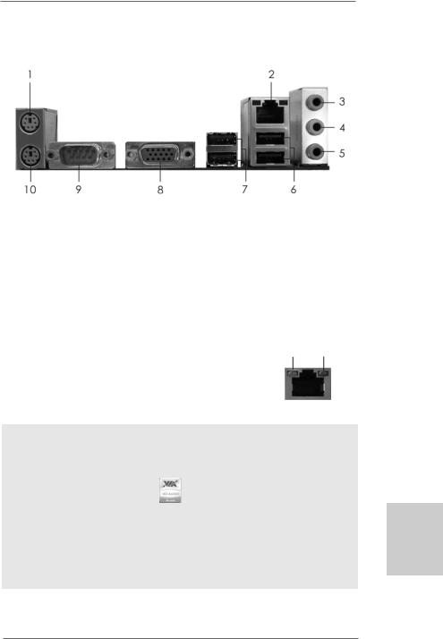
I/O Panel (N68C-GS FX)
1 |
PS/2 |
Mouse Port (Green) |
6 |
USB 2.0 |
Ports |
(USB01) |
* 2 |
RJ-45 |
Port |
7 |
USB 2.0 |
Ports |
(USB23) |
3 |
Line In (Light Blue) |
8 |
VGA Port |
|
|
|
4 |
Front Speaker (Lime) |
9 |
COM Port |
|
||
5 |
Microphone (Pink) |
10 |
PS/2 Keyboard Port (Purple) |
|||
*There are two LED next to the LAN port. Please refer to the table below for the LAN port LED indications.
LAN Port LED Indications
Activity/Link LED |
|
|
SPEED LED |
ACT/LINK |
SPEED |
||
|
|
LED |
LED |
||||
Status |
Description |
|
Status |
|
Description |
||
|
|
|
|
||||
Off |
No Activity |
|
Off |
|
10Mbps connection |
|
|
Blinking |
Data Activity |
|
Orange |
|
100Mbps connection |
|
|
|
|
|
Green |
|
1Gbps connection |
LAN Port |
|
|
|
|
|
|
|
||
To enable Multi-Streaming function, you need to connect a front panel audio cable to the front panel audio header. After restarting your computer, you will find “VIA HD Audio Deck” tool on your system. Please follow below instructions according to the OS you install.
For Windows® XP / XP 64-bit OS: |
|
Please click “VIA HD Audio Deck” icon |
, and click “Speaker”. Then you are allowed to |
select “2 Channel” or “4 Channel”. Click “Power” to save your change.
For Windows® 7 / 7 64-bit / VistaTM / VistaTM 64-bit OS:
Please click “VIA HD Audio Deck” icon  , and click “Advanced Options” on the left side
on the bottom. In “Advanced Options” screen, select “Independent Headphone”, and click “OK” to save your change.
3
English
ASRock N68C-GS FX / N68C-S FX Motherboard
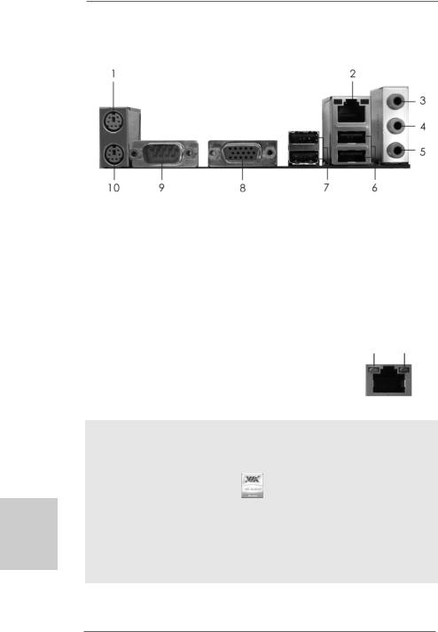
I/O Panel (N68C-S FX)
English
4
1 |
PS/2 |
Mouse Port (Green) |
6 |
USB 2.0 |
Ports |
(USB01) |
* 2 |
RJ-45 |
Port |
7 |
USB 2.0 |
Ports |
(USB23) |
3 |
Line In (Light Blue) |
8 |
VGA Port |
|
|
|
4 |
Front Speaker (Lime) |
9 |
COM Port |
|
||
5 |
Microphone (Pink) |
10 |
PS/2 Keyboard Port (Purple) |
|||
*There are two LED next to the LAN port. Please refer to the table below for the LAN port LED indications.
LAN Port LED Indications
Activity/Link LED |
|
SPEED LED |
ACT/LINK |
SPEED |
||
|
LED |
LED |
||||
Status |
Description |
|
Status |
Description |
||
|
|
|
||||
Off |
No Activity |
|
Off |
10Mbps connection |
|
|
Blinking |
Data Activity |
|
Green or |
100Mbps connection |
|
|
|
|
|
Orange |
|
LAN Port |
|
|
|
|
|
|
||
To enable Multi-Streaming function, you need to connect a front panel audio cable to the front panel audio header. After restarting your computer, you will find “VIA HD Audio Deck” tool on your system. Please follow below instructions according to the OS you install.
For Windows® XP / XP 64-bit OS: |
|
Please click “VIA HD Audio Deck” icon |
, and click “Speaker”. Then you are allowed to |
select “2 Channel” or “4 Channel”. Click “Power” to save your change.
For Windows® 7 / 7 64-bit / VistaTM / VistaTM 64-bit OS:
Please click “VIA HD Audio Deck” icon  , and click “Advanced Options” on the left side
on the bottom. In “Advanced Options” screen, select “Independent Headphone”, and click “OK” to save your change.
ASRock N68C-GS FX / N68C-S FX Motherboard

1. Introduction
Thank you for purchasing ASRock N68C-GS FX / N68C-S FX motherboard, a reliable motherboard produced under ASRock’s consistently stringent quality control. It delivers excellent performance with robust design conforming to ASRock’s commitment to quality and endurance.
In this manual, chapter 1 and 2 contain introduction of the motherboard and step-by-step guide to the hardware installation. Chapter 3 and 4 contain the configuration guide to BIOS setup and information of the Support CD.
Because the motherboard specifications and the BIOS software might be updated, the content of this manual will be subject to change without notice. In case any modifications of this manual occur, the updated version will be available on ASRock website without further notice. You may find the latest VGA cards and CPU support lists on ASRock website as well. ASRock website http://www.asrock.com
If you require technical support related to this motherboard, please visit our website for specific information about the model you are using. www.asrock.com/support/index.asp
1 . 1 Package Contents
One ASRock N68C-GS FX / N68C-S FX Motherboard
(Micro ATX Form Factor: 9.6-in x 8.2-in, 24.4 cm x 20.8 cm) One ASRock N68C-GS FX / N68C-S FX Quick Installation Guide One ASRock N68C-GS FX / N68C-S FX Support CD
Two Serial ATA (SATA) Data Cables (Optional) One I/O Panel Shield
English
5
ASRock N68C-GS FX / N68C-S FX Motherboard

English
6
1.2 Specifications
Platform |
- Micro ATX Form Factor: 9.6-in x 8.2-in, 24.4 cm x 20.8 cm |
CPU |
- Support for Socket AM3+ processors (see CAUTION 1) |
|
- Support for AM3 processors: AMD PhenomTM II X6 / X4 / X3 / |
|
X2 (except 920 / 940) / Athlon II X4 / X3 / X2 / Sempron |
|
processors |
|
- Support for Socket AM2+ / AM2 processors: AMD PhenomTM |
|
FX / Phenom / Athlon 64 FX / Athlon 64 X2 Dual-Core / Athlon |
|
X2 Dual-Core / Athlon 64 / Sempron processor |
|
- Supports 8-Core CPU |
|
- Supports UCC feature (Unlock CPU Core) (see CAUTION 2) |
|
- Supports AMD’s Cool ‘n’ QuietTM Technology |
|
- FSB 1000 MHz (2.0 GT/s) |
|
- Supports Untied Overclocking Technology (see CAUTION 3) |
|
- Supports Hyper-Transport Technology |
Chipset |
- NVIDIA® GeForce 7025 / nForce 630a |
Memory |
- Dual Channel DDR3/DDR2 Memory Technology |
|
(see CAUTION 4) |
|
- 2 x DDR3 DIMM slots |
|
- Support DDR3 1600/1333/1066/800 non-ECC, un-buffered |
|
memory (see CAUTION 5) |
|
- Max. capacity of system memory: 8GB (see CAUTION 6) |
|
- 2 x DDR2 DIMM slots |
|
- Support DDR2 1066/800/667/533 non-ECC, un-buffered |
|
memory (see CAUTION 7) |
|
- Max. capacity of system memory: 8GB (see CAUTION 6) |
Expansion Slot |
- 1 x PCI Express x16 slot |
|
- 1 x PCI Express x1 slot |
|
- 2 x PCI slots |
Graphics |
- Integrated NVIDIA® GeForce 7025 graphics |
|
- DX9.0 VGA, Pixel Shader 3.0 |
|
- Max. shared memory 256MB (see CAUTION 8) |
|
- Supports D-Sub with max. resolution up to 1920x1440 |
|
@ 60Hz |
Audio |
- 5.1 CH HD Audio (VIA® VT1705 Audio Codec) |
LAN |
- N68C-GS FX |
|
Realtek Giga PHY RTL8211CL, speed 10/100/1000 Mb/s |
|
- N68C-S FX |
|
Realtek PHY RTL8201EL, speed 10/100 Mb/s |
|
- Supports Wake-On-LAN |
ASRock N68C-GS FX / N68C-S FX Motherboard

|
- Supports PXE |
Rear Panel I/O |
I/O Panel |
|
- 1 x PS/2 Mouse Port |
|
- 1 x PS/2 Keyboard Port |
|
- 1 x Serial Port: COM1 |
|
- 1 x VGA Port |
|
- 4 x Ready-to-Use USB 2.0 Ports |
|
- 1 x RJ-45 LAN Port with LED (ACT/LINK LED and SPEED LED) |
|
- HD Audio Jack: Line in / Front Speaker / Microphone |
Connector |
- 4 x SATA2 3.0Gb/s connectors, support RAID (RAID 0, RAID 1, |
|
RAID 0+1, RAID 5, JBOD), NCQ and “Hot Plug” functions |
|
(see CAUTION 9) |
|
- 1 x ATA133 IDE connector (supports 2 x IDE devices) |
|
- 1 x Floppy connector |
|
- 1 x Print Port header |
|
- CPU/Chassis/Power FAN connector |
|
- 24 pin ATX power connector |
|
- 4 pin 12V power connector |
|
- CD in header |
|
- Front panel audio header |
|
- 3 x USB 2.0 headers (support 6 USB 2.0 ports) |
BIOS Feature |
- 8Mb AMI Legal BIOS |
|
- Supports “Plug and Play” |
|
- ACPI 1.1 Compliance Wake Up Events |
|
- Supports jumperfree |
|
- SMBIOS 2.3.1 Support |
|
- CPU, VCCM, NB Voltage Multi-adjustment |
Support CD |
- Drivers, Utilities, AntiVirus Software (Trial Version), CyberLink |
|
MediaEspresso 6.5 Trial, ASRock Software Suite (CyberLink |
|
DVD Suite - OEM and Trial; Creative Sound Blaster X-Fi MB - |
|
Trial; ASRock MAGIX Multimedia Suite - OEM) |
Unique Feature |
- ASRock OC Tuner (see CAUTION 10) |
|
- ASRock Intelligent Energy Saver (see CAUTION 11) |
|
- ASRock Instant Boot |
|
- ASRock Instant Flash (see CAUTION 12) |
|
- ASRock OC DNA (see CAUTION 13) |
|
- ASRock APP Charger (see CAUTION 14) |
|
- ASRock SmartView (see CAUTION 15) |
|
- ASRock XFast USB (see CAUTION 16) |
|
- ASRock XFast LAN (see CAUTION 17) |
|
- Hybrid Booster: |
|
- CPU Frequency Stepless Control (see CAUTION 18) |
7
English
ASRock N68C-GS FX / N68C-S FX Motherboard

|
- ASRock U-COP (see CAUTION 19) |
|
- Boot Failure Guard (B.F.G.) |
|
- ASRock AM2 Boost: ASRock Patented Technology to boost |
|
memory performance up to 12.5% (see CAUTION 20) |
Hardware |
- CPU Temperature Sensing |
Monitor |
- Chassis Temperature Sensing |
|
- CPU/Chassis/Power Fan Tachometer |
|
- CPU Quiet Fan |
|
- Voltage Monitoring: +12V, +5V, +3.3V, Vcore |
OS |
- Microsoft® Windows® 7 / 7 64-bit / VistaTM / VistaTM 64-bit / |
|
XP / XP 64-bit compliant |
Certifications |
- FCC, CE, WHQL |
* For detailed product information, please visit our website: http://www.asrock.com
WARNING
Please realize that there is a certain risk involved with overclocking, including adjusting the setting in the BIOS, applying Untied Overclocking Technology, or using the third-party overclocking tools. Overclocking may affect your system stability, or even cause damage to the components and devices of your system. It should be done at your own risk and expense. We are not responsible for possible damage caused by overclocking.
English
8
ASRock N68C-GS FX / N68C-S FX Motherboard

CAUTION!
1.This motherboard supports CPU up to 95W. Please refer to our website for
CPU support list. ASRock website http://www.asrock.com
2.UCC (Unlock CPU Core) feature simplifies AMD CPU activation. As long as a simple switch of the BIOS option “ASrock UCC”, you can unlock the extra CPU core to enjoy an instant performance boost. When UCC feature is enabled, the dual-core or triple-core CPU will boost to the quad-core CPU, and some CPU, including quad-core CPU, can also increase L3 cache size up to 6MB, which means you can enjoy the upgrade CPU performance with a better price. Please be noted that UCC feature is supported with AM2+ / AM3 / AM3+ CPU only, and in addition, not every AM2+ / AM3 / AM3+ CPU can support this function because some CPU’s hidden core may be malfunctioned.
3.This motherboard supports Untied Overclocking Technology. Please read “Untied Overclocking Technology” on page 24 for details.
4.This motherboard supports Dual Channel Memory Technology. Before you implement Dual Channel Memory Technology, make sure to read the installation guide of memory modules on page 14 for proper installation.
5.Whether 1600MHz memory speed is supported depends on the AM3 / AM3+ CPU you adopt. If you want to adopt DDR3 1600 memory module on this motherboard, please refer to the memory support list on our website for the compatible memory modules.
ASRock website http://www.asrock.com
6.Due to the operating system limitation, the actual memory size may be less than 4GB for the reservation for system usage under Windows® 7
/VistaTM / XP. For Windows® OS with 64-bit CPU, there is no such limitation.
7.Whether 1066MHz memory speed is supported depends on the AM2+
/AM3 CPU you adopt. If you want to adopt DDR2 1066 memory module on this motherboard, please refer to the memory support list on our website for the compatible memory modules.
ASRock website http://www.asrock.com
8.The maximum shared memory size is defined by the chipset vendor and is subject to change. Please check NVIDIA® website for the latest information.
9.Before installing SATAII hard disk to SATAII connector, please read the “SATAII Hard Disk Setup Guide” on page 26 of “User Manual” in the support CD to adjust your SATAII hard disk drive to SATAII mode. You can also connect SATA hard disk to SATAII connector directly.
10.It is a user-friendly ASRock overclocking tool which allows you to surveil your system by hardware monitor function and overclock your hardware devices to get the best system performance under Windows® environment. Please visit our website for the operation procedures of ASRock OC Tuner. ASRock website: http://www.asrock.com
English
9
ASRock N68C-GS FX / N68C-S FX Motherboard

English
1 0
11.Featuring an advanced proprietary hardware and software design, Intelligent Energy Saver is a revolutionary technology that delivers unparalleled power savings. The voltage regulator can reduce the number of output phases to improve efficiency when the CPU cores are idle. In other words, it is able to provide exceptional power saving and improve power efficiency without sacrificing computing performance. To use Intelligent Energy Saver function, please enable Cool ‘n’ Quiet option in the BIOS setup in advance. Please visit our website for the operation procedures of Intelligent Energy Saver.
ASRock website: http://www.asrock.com
12.ASRock Instant Flash is a BIOS flash utility embedded in Flash ROM. This convenient BIOS update tool allows you to update system BIOS without entering operating systems first like MS-DOS or Windows®. With this utility, you can press <F6> key during the POST or press <F2> key to BIOS setup menu to access ASRock Instant Flash. Just launch this tool and save the new BIOS file to your USB flash drive, floppy disk or hard drive, then you can update your BIOS only in a few clicks without preparing an additional floppy diskette or other complicated flash utility. Please be noted that the USB flash drive or hard drive must use FAT32/ 16/12 file system.
13.The software name itself – OC DNA literally tells you what it is capable of. OC DNA, an exclusive utility developed by ASRock, provides a convenient way for the user to record the OC settings and share with others.
It helps you to save your overclocking record under the operating system and simplifies the complicated recording process of overclocking settings. With OC DNA, you can save your OC settings as a profile and share with your friends! Your friends then can load the OC profile to their own system to get the same OC settings as yours! Please be noticed that the OC profile can only be shared and worked on the same motherboard.
14.If you desire a faster, less restricted way of charging your Apple devices, such as iPhone/iPod/iPad Touch, ASRock has prepared a wonderful solution for you - ASRock APP Charger. Simply installing the APP Charger driver, it makes your iPhone charged much quickly from your computer and up to 40% faster than before. ASRock APP Charger allows you to quickly charge many Apple devices simultaneously and even supports continuous charging when your PC enters into Standby mode (S1), Suspend to RAM (S3), hibernation mode (S4) or power off (S5). With APP Charger driver installed, you can easily enjoy the marvelous charging experience than ever.
ASRock website: http://www.asrock.com/Feature/AppCharger/index.asp
ASRock N68C-GS FX / N68C-S FX Motherboard
15.SmartView, a new function of internet browser, is the smart start page for IE that combines your most visited web sites, your history, your Facebook friends and your real-time newsfeed into an enhanced view for a more personal Internet experience. ASRock motherboards are exclusively equipped with the SmartView utility that helps you keep in touch with friends on-the-go. To use SmartView feature, please make sure your OS version is Windows® 7 / 7 64 bit / VistaTM / VistaTM 64 bit, and your browser version is IE8.
ASRock website: http://www.asrock.com/Feature/SmartView/index.asp
16.ASRock XFast USB can boost USB storage device performance. The performance may depend on the property of the device.
17.ASRock XFast LAN provides a faster internet access, which includes below benefits. LAN Application Prioritization: You can configure your application priority ideally and/or add new programs. Lower Latency in Game: After setting online game priority higher, it can lower the latency in game. Traffic Shaping: You can watch Youtube HD video and download files simultaneously. Real-Time Analysis of Your Data: With the status window, you can easily recognize which data streams you are currently transferring.
18.Although this motherboard offers stepless control, it is not recommended to perform over-clocking. Frequencies other than the recommended CPU bus frequencies may cause the instability of the system or damage the CPU.
19.While CPU overheat is detected, the system will automatically shutdown. Before you resume the system, please check if the CPU fan on the motherboard functions properly and unplug the power cord, then plug it back again. To improve heat dissipation, remember to spray thermal grease between the CPU and the heatsink when you install the PC system.
20.This motherboard supports ASRock AM2 Boost overclocking technology. If you enable this function in the BIOS setup, the memory performance will improve up to 12.5%, but the effect still depends on the AM2 CPU you adopt. Enabling this function will overclock the chipset/CPU reference clock. However, we can not guarantee the system stability for all CPU/DRAM configurations. If your system is unstable after AM2 Boost function is enabled, it may not be applicative to your system. You may choose to disable this function for keeping the stability of your system.
English
1 1
ASRock N68C-GS FX / N68C-S FX Motherboard
2. Installation
This is a Micro ATX form factor (9.6-in x 8.2-in, 24.4 cm x 20.8 cm) motherboard. Before you install the motherboard, study the configuration of your chassis to ensure that the motherboard fits into it.
Pre-installation Precautions
Take note of the following precautions before you install motherboard components or change any motherboard settings.
Before you install or remove any component, ensure that the power is switched off or the power cord is detached from the power supply. Failure to do so may cause severe damage to the motherboard, peripherals, and/or components.
1.Unplug the power cord from the wall socket before touching any component.
2.To avoid damaging the motherboard components due to static electricity, NEVER place your motherboard directly on the carpet or the like. Also remember to use a grounded wrist strap or touch a safety grounded object before you handle components.
3.Hold components by the edges and do not touch the ICs.
4.Whenever you uninstall any component, place it on a grounded antistatic pad or in the bag that comes with the component.
5.When placing screws into the screw holes to secure the motherboard to the chassis, please do not over-tighten the screws! Doing so may damage the motherboard.
English
1 2
ASRock N68C-GS FX / N68C-S FX Motherboard
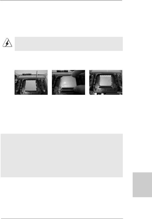
2.1 CPU Installation
Step 1. Unlock the socket by lifting the lever up to a 90o angle.
Step 2. Position the CPU directly above the socket such that the CPU corner with the golden triangle matches the socket corner with a small triangle.
Step 3. Carefully insert the CPU into the socket until it fits in place.
The CPU fits only in one correct orientation. DO NOT force the CPU into the socket to avoid bending of the pins.
Step 4. When the CPU is in place, press it firmly on the socket while you push down the socket lever to secure the CPU. The lever clicks on the side tab to indicate that it is locked.
Lever 90°Up |
|
|
|
CPU Golden Triangle |
|
|
Socker Corner Small Triangle |
|
STEP 1: |
STEP 2 / STEP 3: |
STEP 4: |
Lift Up The Socket Lever |
Match The CPU Golden Triangle |
Push Down And Lock |
|
To The Socket Corner Small |
The Socket Lever |
|
Triangle |
|
2.2 Installation of CPU Fan and Heatsink
After you install the CPU into this motherboard, it is necessary to install a larger heatsink and cooling fan to dissipate heat. You also need to spray thermal grease between the CPU and the heatsink to improve heat dissipation. Make sure that the CPU and the heatsink are securely fastened and in good contact with each other. Then connect the CPU fan to the CPU FAN connector (CPU_FAN1, see Page 2, No. 2). For proper installation, please kindly refer to the instruction manuals of the CPU fan and the heatsink.
English
1 3
ASRock N68C-GS FX / N68C-S FX Motherboard
English
2.3 Installation of Memory Modules (DIMM)
This motherboard provides two 240-pin DDR2 (Double Data Rate 2) DIMM slots and two 240-pin DDR3 (Double Data Rate 3) DIMM slots, and supports Dual Channel Memory Technology. For dual channel configuration, you always need to install identical (the same brand, speed, size and chip-type) DDR2/DDR3 DIMM pair in the slots of the same color. In other words, you have to install identical DDR2 DIMM pair in Dual Channel (DDRII_1 and DDRII_2; Yellow slots; see p.2 No.6), or identical DDR3 DIMM pair in Dual Channel (DDR3_A1 and DDR3_B1; Blue slots; see p.2 No.7), so that Dual Channel Memory Technology can be activated. You may refer to the Dual Channel Memory Configuration Table below.
Dual Channel DDR2 Memory Configurations
(DS: Double Side, SS: Single Side)
|
DDRII_1 |
DDRII_2 |
|
(Yellow Slot) |
(Yellow Slot) |
|
|
|
2 memory modules |
SS |
SS |
2 memory modules |
DS |
DS |
Dual Channel DDR3 Memory Configurations
(DS: Double Side, SS: Single Side)
|
DDR3_A1 |
DDR3_B1 |
|
(Blue Slot) |
(Blue Slot) |
|
|
|
2 memory modules |
SS |
SS |
2 memory modules |
DS |
DS |
1.If you want to install two memory modules, for optimal compatibility and reliability, it is recommended to install them in the slots of the same color. In other words, install them in the set of blue slots (DDR3_A1 and DDR3_B1), or in the set of yellow slots (DDRII_1 and DDRII_2).
2.If only one memory module is installed in the DIMM slot on this motherboard, it is unable to activate the Dual Channel Memory Technology.
3.It is not allowed to install a DDR3 memory module into DDR2 slot or install a DDR2 memory module into DDR3 slot; otherwise, this motherboard and DIMM may be damaged.
4.DDR2 and DDR3 memory modules cannot be installed on this motherboard at the same time.
5.DDR3 memory module is only supported by installing AM3/AM3+ CPU. DDR2 memory module is only supported by installing AM2/ AM2+/AM3 CPU.
1 4
ASRock N68C-GS FX / N68C-S FX Motherboard
Installing a DIMM
Please make sure to disconnect power supply before adding or removing DIMMs or the system components.
Step 1. Unlock a DIMM slot by pressing the retaining clips outward.
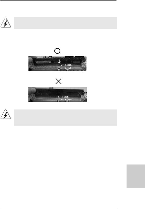
Step 2. Align a DIMM on the slot such that the notch on the DIMM matches the break on the slot.
The DIMM only fits in one correct orientation. It will cause permanent damage to the motherboard and the DIMM if you force the DIMM into the slot at incorrect orientation.
Step 3. Firmly insert the DIMM into the slot until the retaining clips at both ends fully snap back in place and the DIMM is properly seated.
English
1 5
ASRock N68C-GS FX / N68C-S FX Motherboard

2.4 Expansion Slots (PCI and PCI Express Slots)
There are 2 PCI slots and 2 PCI Express slots on this motherboard.
PCI slots: PCI slots are used to install expansion cards that have the 32-bit PCI interface.
PCIE slots: PCIE1 (PCIE x1 slot) is used for PCI Express cards with x1 lane width cards, such as Gigabit LAN card, SATA2 card, etc.
PCIE2 (PCIE x16 slot) is used for PCI Express cards with x16 lane width graphics cards.
Installing an expansion card
Step 1. Before installing the expansion card, please make sure that the power supply is switched off or the power cord is unplugged. Please read the documentation of the expansion card and make necessary hardware settings for the card before you start the installation.
Step 2. Remove the bracket facing the slot that you intend to use. Keep the screws for later use.
Step 3. Align the card connector with the slot and press firmly until the card is completely seated on the slot.
Step 4. Fasten the card to the chassis with screws.
English
1 6
ASRock N68C-GS FX / N68C-S FX Motherboard

2.5 Easy Multi Monitor Feature
This motherboard supports Multi Monitor upgrade. With the internal onboard VGA and |
|
|
the external add-on PCI Express VGA card, you can easily enjoy the benefits of Multi |
|
|
Monitor feature. Please refer to the following steps to set up a multi monitor |
|
|
environment: |
|
|
1. Install the NVIDIA® PCI Express VGA card to PCIE2 (PCIE x16 slot). Please refer |
|
|
to page 16 for proper expansion card installation procedures for details. |
|
|
2. Connect the D-Sub monitor cable to the D-Sub port on the I/O panel of this |
|
|
motherboard. Connect another D-Sub monitor cable to the D-Sub connector of |
|
|
the add-on PCI Express VGA card. Connect the DVI-D monitor cable to the |
|
|
DVI-D connector of the add-on PCI Express VGA card. |
|
|
3. Boot your system. Press <F2> or <Del> to enter BIOS setup. Enter “Share |
|
|
Memory” option to adjust the memory capability to [16MB], [32MB], [64MB], |
|
|
[128MB] or [256MB] to enable the function of onboard VGA/D-sub. Please make |
|
|
sure that the value you select is less than the total capability of the system |
|
|
memory. If you do not adjust the BIOS setup, the default value of “Share Memory”, |
|
|
[Auto], will disable onboard VGA/D-Sub function when the add-on VGA card is |
|
|
inserted to this motherboard. |
|
|
4. Install the onboard VGA driver to your system. If you have installed the onboard |
|
|
VGA driver already, there is no need to install it again. |
|
|
5. Set up a multi-monitor display. |
|
|
For Windows® XP / XP 64-bit OS: |
|
|
Right click the desktop, choose “Properties”, and select the “Settings” tab so |
|
|
that you can adjust the parameters of the multi-monitor according to the steps |
|
|
below. |
|
|
A. Click the “Identify” button to display a large number on each monitor. |
|
|
B. Right-click the display icon in the Display Properties dialog that you wish |
|
|
to be your primary monitor, and then select “Primary”. When you use |
|
|
multiple monitors with your card, one monitor will always be Primary, and |
|
|
all additional monitors will be designated as Secondary. |
|
|
C. Select the display icon identified by the number 2. |
|
|
D. Click “Extend my Windows desktop onto this monitor”. |
|
|
E. Right-click the display icon and select “Attached”, if necessary. |
|
|
F. Set the “Screen Resolution” and “Color Quality” as appropriate for the |
English |
|
second monitor. Click “Apply” or “OK” to apply these new values. |
||
|
||
G. Repeat steps C through E for the diaplay icon identified by the number |
|
|
one, two and three. |
|
|
For Windows® 7 / 7 64-bit / VistaTM / VistaTM 64-bit OS: |
|
|
Right click the desktop, choose “Personalize”, and select the “Display |
|
|
Settings” tab so that you can adjust the parameters of the multi-monitor |
|
|
according to the steps below. |
|
|
A. Click the number ”2” icon. |
1 7 |
|
|
ASRock N68C-GS FX / N68C-S FX Motherboard

B.Click the items “This is my main monitor” and “Extend the desktop onto this monitor”.
C.Click “OK” to save your change.
D.Repeat steps A through C for the display icon identified by the number one, two and three.
6.Use Multi Monitor feature. Click and drag the display icons to positions representing the physical setup of your monitors that you would like to use. The placement of display icons determines how you move items from one monitor to another.
English
1 8
ASRock N68C-GS FX / N68C-S FX Motherboard
2.6Jumpers Setup
The illustration shows how jumpers are setup. When the jumper cap is placed on pins, the jumper is “Short”. If no jumper cap is placed on pins, the jumper is “Open”. The
illustration shows a 3-pin jumper whose pin1 Short Open and pin2 are “Short” when jumper cap is
placed on these 2 pins.
Jumper |
Setting |
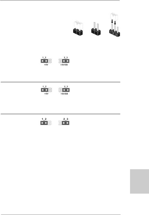
PS2_USB_PWR1 |
Short pin2, pin3 to enable |
(see p.2, No. 1) |
+5VSB (standby) for PS/2 or |
|
USB01/23 wake up events. |
Note: To select +5VSB, it requires 2 Amp and higher standby current provided by power supply.
USB_PWR2 |
Short pin2, pin3 to enable |
(see p.2, No. 15) |
+5VSB (standby) for |
|
USB4_5/6_7/8_9 wake up |
|
events. |
Note: To select +5VSB, it requires 2 Amp and higher standby current provided by power supply.
Clear CMOS Jumper
(CLRCMOS1)
(see p.2, No. 22) Default Clear CMOS
Note: CLRCMOS1 allows you to clear the data in CMOS. The data in CMOS includes system setup information such as system password, date, time, and system setup parameters. To clear and reset the system parameters to default setup, please turn off the computer and unplug the power cord from the power supply. After waiting for 15 seconds, use a jumper cap to short pin2 and pin3
English
1 9
ASRock N68C-GS FX / N68C-S FX Motherboard

English
on CLRCMOS1 for 5 seconds. However, please do not clear the CMOS right after you update the BIOS. If you need to clear the CMOS when you just finish updating the BIOS, you must boot up the system first, and then shut it down before you do the clear-CMOS action.
2.7 Onboard Headers and Connectors
Onboard headers and connectors are NOT jumpers. Do NOT place jumper caps over these headers and connectors. Placing jumper caps over the headers and connectors will cause permanent damage of the motherboard!
•
Floppy Connector
(33-pin FLOPPY1)
(see p.2 No. 24)
the red-striped side to Pin1
Note: Make sure the red-striped side of the cable is plugged into Pin1 side of the connector.
Primary IDE connector (Blue)
(39-pin IDE1, see p.2 No. 9)
connect the blue end |
connect the black end |
to the motherboard |
to the IDE devices |
80-conductor ATA 66/100/133 cable
Note: Please refer to the instruction of your IDE device vendor for the details.
Serial ATAII Connectors
(SATAII_1 (PORT 0.0): |
SATAII_1 |
SATAII_3 |
|
see p.2, No. 10) |
(PORT 0.0) |
(PORT 1.0) |
|
|
|
||
(SATAII_2 (PORT 0.1): |
|
|
|
see p.2, No. 13) |
|
|
|
(SATAII_3 (PORT 1.0): |
SATAII_2 |
SATAII_4 |
|
(PORT 0.1) |
(PORT 1.1) |
||
see p.2, No. 11) |
|||
|
|
||
(SATAII_4 (PORT 1.1): |
|
|
|
see p.2, No. 12) |
|
|
These four Serial ATAII (SATAII) connectors support SATAII
or SATA hard disk for internal storage devices. The current SATAII interface allows up to 3.0 Gb/s data transfer rate.
Serial ATA (SATA) |
Either end of the SATA data cable |
Data Cable |
can be connected to the SATA / |
(Optional) |
SATAII hard disk or the SATAII |
|
connector on the motherboard. |
2 0
ASRock N68C-GS FX / N68C-S FX Motherboard
USB 2.0 Headers |
Besides four default USB 2.0 |
(9-pin USB8_9) |
ports on the I/O panel, there are |
(see p.2 No. 16) |
three USB 2.0 headers on this |
|
motherboard. Each USB 2.0 |
|
header can support two USB |
|
2.0 ports. |
(9-pin USB6_7) |
|
(see p.2 No. 17) |
|
(9-pin USB4_5)
(see p.2 No. 18)
Print Port Header |
This is an interface for print |
(25-pin LPT1) |
port cable that allows |
(see p.2 No. 23) |
convenient connection of printer |
|
devices. |
Internal Audio Connectors |
|
|
|
|
|
This connector allows you |
|
(4-pin CD1) |
|
|
|
|
CD1 |
to receive stereo audio input |
|
(CD1: see p.2 No. 26) |
|
|
|
|
|
from sound sources such as |
|
|
L-CD GND GND |
|
|||||
RCD- |
|
a CD-ROM, DVD-ROM, TV |
|||||
|
|
|
|
|
|
|
|
|
|
|
|
|
|
|
tuner card, or MPEG card. |
|
|
|
|
|
|
|
|
Front Panel Audio Header |
|
|
|
|
|
This is an interface for the front |
|
(9-pin HD_AUDIO1) |
|
|
|
|
|
panel audio cable that allows |
|
(see p.2, No. 27) |
|
|
|
|
|
convenient connection and |
|
|
|
|
|
|
|
|
control of audio devices. |
1.High Definition Audio supports Jack Sensing, but the panel wire on the chassis must support HDA to function correctly. Please follow the
instruction in our manual and chassis manual to install your system.
2.If you use AC’97 audio panel, please install it to the front panel audio header as below:
A.Connect Mic_IN (MIC) to MIC2_L.
B.Connect Audio_R (RIN) to OUT2_R and Audio_L (LIN) to OUT2_L.
2 1
English
ASRock N68C-GS FX / N68C-S FX Motherboard
C.Connect Ground (GND) to Ground (GND).
D.MIC_RET and OUT_RET are for HD audio panel only. You don’t need to connect them for AC’97 audio panel.
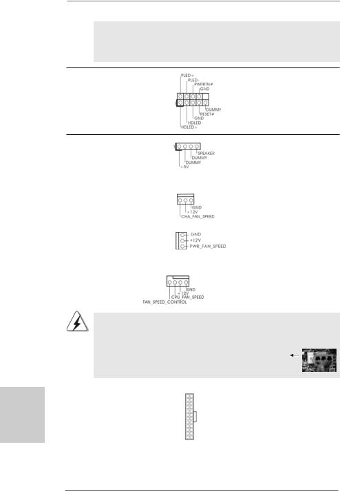
System Panel Header |
This header accommodates |
(9-pin PANEL1) |
several system front panel |
(see p.2 No. 20) |
functions. |
English
Chassis Speaker Header |
|
Please connect the chassis |
(4-pin SPEAKER 1) |
|
speaker to this header. |
(see p.2 No. 19) |
|
|
|
|
|
Chassis and Power Fan Connectors |
Please connect the fan cables |
|
(3-pin CHA_FAN1) |
|
to the fan connectors and |
(see p.2 No. 21) |
|
match the black wire to the |
|
|
ground pin. |
(3-pin PWR_FAN1) |
|
|
(see p.2 No. 25) |
|
|
|
|
|
CPU Fan Connector |
4 3 2 1 |
Please connect the CPU fan |
(4-pin CPU_FAN1) |
|
cable to this connector and |
(see p.2 No. 2) |
|
match the black wire to the |
|
|
ground pin. |
Though this motherboard provides 4-Pin CPU fan (Quiet Fan) support, the 3-Pin CPU fan still can work successfully even without the fan speed control function. If you plan to connect the 3-Pin CPU fan to the CPU fan connector on this motherboard, please connect it to Pin 1-3.
|
|
|
Pin 1-3 Connected |
|
|
|
3-Pin Fan Installation |
|
|
|
|
ATX Power Connector |
12 |
24 |
Please connect an ATX power |
|
|
||
(24-pin ATXPWR1) |
|
|
supply to this connector. |
(see p.2 No. 8) |
|
|
|
|
1 |
13 |
|
2 2
ASRock N68C-GS FX / N68C-S FX Motherboard
|
Though this motherboard provides 24-pin ATX power connector, |
12 |
24 |
|
|
it can still work if you adopt a traditional 20-pin ATX power supply. |
|
|
|
|
To use the 20-pin ATX power supply, please plug your power |
|
|
|
|
supply along with Pin 1 and Pin 13. |
|
|
|
|
|
20-PinATX Power Supply Installation |
1 |
13 |
|
|
|
||
|
|
|
||
|
|
|
|
|
ATX 12V Power Connector |
Please note that it is necessary |
|||
(4-pin ATX12V1) |
to connect a power supply with |
|||
(see p.2 No. 3) |
ATX 12V plug to this connector. |
|||
|
|
Failing to do so will cause power |
||
|
|
up failure. |
|
|
English
2 3
ASRock N68C-GS FX / N68C-S FX Motherboard

English
2.8 Driver Installation Guide
To install the drivers to your system, please insert the support CD to your optical drive first. Then, the drivers compatible to your system can be auto-detected and listed on the support CD driver page. Please follow the order from up to bottom side to install those required drivers. Therefore, the drivers you install can work properly.
2.9Installing Windows® 7 / 7 64-bit / VistaTM /
VistaTM 64-bit / XP / XP 64-bit Without RAID Functions
If you just want to install Windows® 7 / 7 64-bit / VistaTM / VistaTM 64-bit / XP / XP 64-bit on your SATA / SATAII HDDs without RAID functions, you don’t have to make a SATA / SATAII driver diskette. Besides, there is no need for you to change the BIOS setting. You can start to install Windows® 7 / 7 64-bit / VistaTM / VistaTM 64-bit / XP / XP 64-bit on your system directly.
2.10 Installing Windows® 7 / 7 64-bit / VistaTM /
VistaTM 64-bit / XP / XP 64-bit With RAID Functions
If you want to install Windows® 7 / 7 64-bit / VistaTM / VistaTM 64-bit / XP / XP 64-bit on your SATA / SATAII HDDs with RAID functions, please refer to the document at the following path in the Support CD for detailed procedures:
..\ RAID Installation Guide
2.11 Untied Overclocking Technology
This motherboard supports Untied Overclocking Technology, which means during overclocking, FSB enjoys better margin due to fixed PCI / PCIE buses. Before you enable Untied Overclocking function, please enter “Overclock Mode” option of BIOS setup to set the selection from [Auto] to [CPU, PCIE, Async.]. Therefore, CPU FSB is untied during overclocking, but PCI / PCIE buses are in the fixed mode so that FSB can operate under a more stable overclocking environment.
Please refer to the warning on page 8 for the possible overclocking risk before you apply Untied Overclocking Technology.
2 4
ASRock N68C-GS FX / N68C-S FX Motherboard

3. BIOS Information
The Flash Memory on the motherboard stores BIOS Setup Utility. When you start up the computer, please press <F2> during the Power-On-Self-Test (POST) to enter BIOS Setup utility; otherwise, POST continues with its test routines. If you wish to enter BIOS Setup after POST, please restart the system by pressing <Ctl> + <Alt> + <Delete>, or pressing the reset button on the system chassis. The BIOS Setup program is designed to be user-friendly. It is a menu-driven program, which allows you to scroll through its various sub-menus and to select among the predetermined choices. For the detailed information about BIOS Setup, please refer to the User Manual (PDF file) contained in the Support CD.
4. Software Support CD information
This motherboard supports various Microsoft® Windows® operating systems: 7 /
7 64-bit / VistaTM / VistaTM 64-bit / XP / XP 64-bit. The Support CD that came with the motherboard contains necessary drivers and useful utilities that will enhance motherboard features. To begin using the Support CD, insert the CD into your CDROM drive. It will display the Main Menu automatically if “AUTORUN” is enabled in your computer. If the Main Menu does not appear automatically, locate and doubleclick on the file “ASSETUP.EXE” from the “BIN” folder in the Support CD to display the menus.
English
2 5
ASRock N68C-GS FX / N68C-S FX Motherboard

1. Einführung
Wir danken Ihnen für den Kauf des ASRock N68C-GS FX / N68C-S FX Motherboard, ein zuverlässiges Produkt, welches unter den ständigen, strengen Qualitätskontrollen von ASRock gefertigt wurde. Es bietet Ihnen exzellente Leistung und robustes Design, gemäß der Verpflichtung von ASRock zu Qualität und Halbarkeit.
Diese Schnellinstallationsanleitung führt in das Motherboard und die schrittweise Installation ein. Details über das Motherboard finden Sie in der Bedienungsanleitung auf der Support-CD.
Da sich Motherboard-Spezifikationen und BIOS-Software verändern können, kann der Inhalt dieses Handbuches ebenfalls jederzeit geändert werden. Für den Fall, dass sich Änderungen an diesem Handbuch ergeben, wird eine neue Version auf der ASRock-Website, ohne weitere Ankündigung, verfügbar sein. Die neuesten Grafikkarten und unterstützten CPUs sind auch auf der ASRock-Website aufgelistet.
ASRock-Website: http://www.asrock.com
Wenn Sie technische Unterstützung zu Ihrem Motherboard oder spezifische Informationen zu Ihrem Modell benötigen, besuchen Sie bitte unsere Webseite:
www.asrock.com/support/index.asp
1.1 Kartoninhalt
ASRock N68C-GS FX / N68C-S FX Motherboard
(Micro ATX-Formfaktor: 24.4 cm x 20.8 cm; 9.6 Zoll x 8.2 Zoll) ASRock N68C-GS FX / N68C-S FX Schnellinstallationsanleitung ASRock N68C-GS FX / N68C-S FX Support-CD
Zwei Seriell-ATA- (SATA) Datenkabel (Option) Ein I/OShield
Deutsch
2 6
ASRock N68C-GS FX / N68C-S FX Motherboard

1.2 Spezifikationen
Plattform |
- Micro ATX-Formfaktor: 24.4 cm x 20.8 cm; 9.6 Zoll x 8.2 Zoll |
CPU |
- Unterstützung von Socket AM3+-Prozessoren |
|
(siehe VORSICHT 1) |
|
- Unterstützung von Socket AM3-Prozessoren: AMD PhenomTM |
|
II X6 / X4 / X3 / X2 (außer 920 / 940) / Athlon X4 / X3 / X2 / |
|
Sempron-Prozessor |
|
- Unterstützung für Socket AM2+ / AM2-Prozessoren: AMD |
|
PhenomTM FX / Phenom / Athlon 64 FX / Athlon 64 X2 Dualkern |
|
/ Athlon X2 Dualkern / Athlon 64 / Sempron-Prozessor |
|
- Acht-Kern-CPU-bereit |
|
- Unterstützt UCC (Unlock CPU Core) (siehe VORSICHT 2) |
|
- Unterstützt Cool ‘n’ QuietTM-Technologie von AMD |
|
- FSB 1000 MHz (2.0 GT/s) |
|
- Unterstützt Untied-Übertaktungstechnologie |
|
(siehe VORSICHT 3) |
|
- Unterstützt Hyper-Transport-Technologie |
Chipsatz |
- NVIDIA® GeForce 7025 / nForce 630a |
Speicher |
- Unterstützung von Dual-Kanal-Speichertechnologie |
|
(siehe VORSICHT 4) |
|
- 2 x Steckplätze für DDR3 |
|
- Unterstützt DDR3 1600/1333/1066/800 non-ECC, |
|
ungepufferter Speicher (siehe VORSICHT 5) |
|
- Max. Kapazität des Systemspeichers: 8GB |
|
(siehe VORSICHT 6) |
|
- 2 x Steckplätze für DDR2 |
|
- Unterstützt DDR2 1066/800/667/533 non-ECC, |
|
ungepufferter Speicher (siehe VORSICHT 7) |
|
- Max. Kapazität des Systemspeichers: 8GB |
|
(siehe VORSICHT 6) |
Erweiterungs- |
- 1 x PCI Express x16-Steckplätze |
steckplätze |
- 1 x PCI Express x1-Steckplätze |
|
- 2 x PCI -Steckplätze |
Onboard-VGA |
- Integrierter NVIDIA® GeForce 7025 Grafikchip |
|
- DX9.0 VGA, Pixel Shader 3.0 |
|
- Maximal gemeinsam genutzter Speicher 256 MB |
|
(siehe VORSICHT 8) |
|
- Unterstützt D-Sub mit einer maximalen Auflösung von |
|
1920 x 1440 bei 60 Hz |
|
|
Audio |
- 5.1 CH HD Audio (VIA® VT1705 Audio Codec) |
Deutsch
2 7
ASRock N68C-GS FX / N68C-S FX Motherboard

Deutsch
2 8
LAN |
- N68C-GS FX |
|
Realtek Giga PHY RTL8211CL, speed 10/100/1000 Mb/s |
|
- N68C-S FX |
|
Realtek PHY RTL8201EL, speed 10/100 Mb/s |
|
- Unterstützt Wake-On-LAN |
|
- Unterstützt PXE |
E/A-Anschlüsse |
I/O Panel |
an der |
- 1 x PS/2-Mausanschluss |
Rückseite |
- 1 x PS/2-Tastaturanschluss |
|
- 1 x Serieller port: COM 1 |
|
- 1 x VGA port |
|
- 4 x Standard-USB 2.0-Anschlüsse |
|
- 1 x RJ-45 LAN Port mit LED (ACT/LINK LED und SPEED LED) |
|
- Audioanschlüsse: Line In / Line Out / Mikrofon |
Anschlüsse |
- 4 x SATA2-Anschlüsse, unterstützt bis 3.0 Gb/s |
|
Datenübertragungsrate, unterstützt RAID (RAID 0, RAID 1, |
|
RAID 0+1, RAID 5, JBOD), NCQ und “Hot Plug” Funktionen |
|
(siehe VORSICHT 9) |
|
- 1 x ATA133 IDE-Anschlüsse (Unterstützt bis 2 IDE-Geräte) |
|
- 1 x FDD-Anschlüsse |
|
- 1 x Druckerport-Anschlussleiste |
|
- CPU/Gehäuse/Stromlüfter-Anschluss |
|
- 24-pinATX-Netz-Header |
|
- 4-pin anschluss für 12V-ATX-Netzteil |
|
- Interne Audio-Anschlüsse |
|
- Anschluss für Audio auf der Gehäusevorderseite |
|
- 3 x USB 2.0-Anschlüsse (Unterstützung 6 zusätzlicher |
|
USB 2.0-Anschlüsse) |
BIOS |
- 8Mb AMI BIOS |
|
- AMI legal BIOS mit Unterstützung für “Plug and Play” |
|
- ACPI 1.1-Weckfunktionen |
|
- JumperFree-Modus |
|
- SMBIOS 2.3.1 |
|
- CPU, VCCM, NB Stromspannung Multianpassung |
|
|
Support-CD |
- Pilotes, utilitaires, logiciel anti-virus (version d’évaluation), |
|
CyberLink MediaEspresso 6.5 Trial, Suite logicielle ASRock |
|
(CyberLink DVD Suite et Version OEM et d’essai; Creative |
|
Sound Blaster X-Fi MB - Testversion; ASRock |
|
MAGIX-Multimedia-Suite - OEM) |
|
|
ASRock N68C-GS FX / N68C-S FX Motherboard
Einzigartige |
- ASRock OC Tuner (siehe VORSICHT 10) |
Eigenschaft |
- ASRock Intelligent Energy Saver (Intelligente |
|
Energiesparfunktion) (siehe VORSICHT 11) |
|
- ASRock Sofortstart |
|
- ASRock Instant Flash (siehe VORSICHT 12) |
|
- ASRock OC DNA (siehe VORSICHT 13) |
|
- ASRock APP Charger (siehe VORSICHT 14) |
|
- ASRock SmartView (siehe VORSICHT 15) |
|
- ASRock XFast USB (siehe VORSICHT 16) |
|
- ASRock XFast LAN (siehe VORSICHT 17) |
|
- Hybrid Booster: |
|
- Schrittloser CPU-Frequenz-Kontrolle |
|
(siehe VORSICHT 18) |
|
- ASRock U-COP (siehe VORSICHT 19) |
|
- Boot Failure Guard (B.F.G. – Systemstartfehlerschutz) |
|
- ASRock AM2 Boost: ASRocks patentgeschützte |
|
Technologie zur Erhöhung der Arbeitsspeicherleistung um |
|
bis zu 12,5% (siehe VORSICHT 20) |
Hardware Monitor - CPU-Temperatursensor
|
- Motherboardtemperaturerkennung |
|
- Drehzahlmessung für CPU/Gehäuse/Stromlüfter |
|
- CPU-Lüftergeräuschdämpfung |
|
- Spannungsüberwachung: +12V, +5V, +3.3V, Vcore |
Betriebssysteme |
- Unterstützt Microsoft® Windows® 7 / 7 64-Bit / VistaTM / |
|
VistaTM 64-Bit / XP / XP 64-Bit |
Zertifizierungen |
- FCC, CE, WHQL |
*Für die ausführliche Produktinformation, besuchen Sie bitte unsere Website: http://www.asrock.com
WARNUNG
Beachten Sie bitte, dass Overclocking, einschließlich der Einstellung im BIOS, Anwenden der Untied Overclocking-Technologie oder Verwenden von Overclocking-Werkzeugen von Dritten, mit einem gewissen Risiko behaftet ist. Overclocking kann sich nachteilig auf die Stabilität Ihres Systems auswirken oder sogar Komponenten und Geräte Ihres Systems beschädigen. Es geschieht dann auf eigene Gefahr und auf Ihre Kosten. Wir übernehmen keine Verantwortung für mögliche Schäden, die aufgrund von Overclocking verursacht wurden.
2 9
Deutsch
ASRock N68C-GS FX / N68C-S FX Motherboard

Deutsch
3 0
VORSICHT!
1.Dieses Motherboard unterstützt CPUs bis 95W. Auf unserer Website finden Sie eine Liste mit unterstützten CPUs.
ASRock-Internetseite: http://www.asrock.com
2.Die UCC-Funktion (Unlock CPU Core; zu Deutsch: CPU-Kern freigeben) vereinfacht die AMD-CPU-Aktivierung. Zur Freigabe des zusätzlichen CPUKerns müssen Sie lediglich die BIOS-Option „ASRock UCC“ umschalten – schon profitieren Sie von einem Leistungsschub. Wenn die UCC-Funktion aktiviert ist, rüstet die Dual-Core- oder Triple-Core-CPU auf eine Quad- Core-CPU auf – einige CPUs (inklusive Quad-Core) können zudem die L3- Cache-Größe auf bis zu 6 MB anheben; das bedeutet verbesserte CPULeistung zu einem geringeren Preis. Bitte beachten Sie, dass die UCCFunktion nur bei AM2+ / AM3 / AM3+-CPUs einsetzbar ist; die Unterstützung besteht jedoch aufgrund möglicher Fehlfunktionen des verborgenen Kerns einiger CPUs auch nicht zwangsläufig bei jeder AM2+ / AM3 / AM3+-CPU.
3.Dieses Motherboard unterstützt die Untied-Übertaktungstechnologie. Unter “Entkoppelte Übertaktungstechnologie” auf Seite 24 finden Sie detaillierte Informationen.
4.Dieses Motherboard unterstützt Dual-Kanal-Speichertechnologie. Vor Implementierung der Dual-Kanal-Speichertechnologie müssen Sie die Installationsanleitung für die Speichermodule auf Seite 14 zwecks richtigerInstallation gelesen haben.
5.Ob die Speichergeschwindigkeit 1600 MHz unterstützt wird, hängt von der von Ihnen eingesetzten AM3 / AM3+-CPU ab. Schauen Sie bitte auf unseren Internetseiten in der Liste mit unterstützten Speichermodulen nach, wenn Sie DDR3 1600-Speichermodule einsetzen möchten.
ASRock-Internetseite: http://www.asrock.com
6.Durch Betriebssystem-Einschränkungen kann die tatsächliche Speichergröße weniger als 4 GB betragen, da unter Windows® 7 / Vista™ / XP etwas Speicher zur Nutzung durch das System reserviert wird. Unter Windows® OS mit 64-Bit-CPU besteht diese Einschränkung nicht.
7.Ob die Speichergeschwindigkeit 1066 MHz unterstützt wird, hängt von der von Ihnen eingesetzten AM2+ / AM3-CPU ab. Schauen Sie bitte auf unseren Internetseiten in der Liste mit unterstützten Speichermodulen nach, wenn Sie DDR2 1066-Speichermodule einsetzen möchten.
ASRock-Internetseite: http://www.asrock.com
8.Die Maximalspeichergröße ist von den Chipshändler definiert und umgetauscht. Bitte überprüfen Sie NVIDIA® website für die neuliche Information.
9.Vor Installation der SATAII-Festplatte an den SATAII-Anschluss lesen Sie bitte “Setup-Anleitung für SATAII-Festplatte” auf Seite 26 der “Bedienungsanleitung” auf der Support-CD, um Ihre SATAII-Festplatte dem SATAII-Modus anzugleichen. Sie können die SATA-Festplatte auch direkt mit dem SATAII-Anschluss verbinden.
ASRock N68C-GS FX / N68C-S FX Motherboard
 Loading...