


M266A
User Manual
Version 3.0
Published July 2003
Copyright©2003 ASRock INC. All rights reserved.
1

Copyright Notice:
No part of this manual may be reproduced, transcribed, transmitted, or translated in any language, in any form or by any means, except duplication of documentation by the purchaser for backup purpose, without written consent of ASRock Inc.
Products and corporate names appearing in this manual may or may not be registered trademarks or copyrights of their respective companies, and are used only for identification or explanation and to the owners’ benefit, without intent to infringe.
Disclaimer:
Specifications and information contained in this manual are furnished for informational use only and subject to change without notice, and should not be constructed as a commitment by ASRock. ASRock assumes no responsibility for any errors or omissions that may appear in this manual.
With respect to the contents of this manual, ASRock does not provide warranty of any kind, either expressed or implied, including but not limited to the implied warranties or conditions of merchantability or fitness for a particular purpose.
In no event shall ASRock, its directors, officers, employees, or agents be liable for any indirect, special, incidental, or consequential damages (including damages for loss of profits, loss of business, loss of data, interruption of business and the like), even if ASRock has been advised of the possibility of such damages arising from any defect or error in the manual or product.
ASRock Website: http://www.asrock.com

 2
2

|
Contents |
|
1 Introduction .......................................................... |
4 |
|
1.1 |
Package Contents ................................................................... |
4 |
1.2 |
Specifications ......................................................................... |
5 |
1.3 |
Motherboard Layout ............................................................... |
7 |
1.4 |
ASRock I/OTM ........................................................................... |
8 |
2 Installation............................................................. |
9 |
|
2.1 |
Screw Holes............................................................................ |
9 |
2.2 |
Pre-installation Precautions .................................................... |
9 |
2.3 |
CPU Installation ....................................................................... |
10 |
2.4 |
Installation of CPU fan and Heatsink ...................................... |
10 |
2.5 |
Installation of Memory Modules (DIMM) .................................. |
11 |
2.6 |
Expansion Slots ...................................................................... |
11 |
2.7 |
Jumpers Setup ....................................................................... |
12 |
2.8 |
Connectors ............................................................................. |
13 |
3 BIOS Setup ............................................................. |
15 |
|
3.1 |
BIOS Setup Utility .................................................................... |
15 |
3.2 |
BIOS Setup Utility Main Menu ................................................. |
15 |
3.3 |
Legend Bar ............................................................................. |
16 |
3.4 |
Standard CMOS Setup ........................................................... |
16 |
3.5 |
Advanced CMOS Setup ......................................................... |
19 |
3.6 |
Advanced Chipset Setup ....................................................... |
20 |
3.7 |
Power Management Setup ..................................................... |
22 |
3.8 |
PCI / Plug and Play Setup ....................................................... |
23 |
3.9 |
Peripheral Setup ..................................................................... |
24 |
3.10 Hardware Monitor Setup ........................................................ |
26 |
|
3.11 Change Supervisor Password / Change User Password ..... |
26 |
|
3.12 Auto Configuration with Optimal Settings .............................. |
26 |
|
3.13 Save Settings and Exit ........................................................... |
26 |
|
3.14 Exit Without Saving ................................................................. |
26 |
|
4 Software Support .................................................. |
27 |
|
4.1 |
Installing Operating System .................................................... |
27 |
4.2 |
Support CD Information .......................................................... |
27 |
4.2.1 Running The Support CD ................................................... |
27 |
|
4.2.2 Drivers Menu ..................................................................... |
27 |
|
4.2.3 Utilities Menu ...................................................................... |
27 |
|
4.2.4 ASRock “PC-DIY Live Demo” Program ............................... |
27 |
|
4.2.5 Contact Information ........................................................... |
27 |
|
3

Chapter 1 Introduction
Thank you for purchasing ASRock M266A motherboard, a reliable motherboard produced under ASRock’s consistently stringent quality control. It delivers excellent performance with robust design conforming to ASRock’s commitment to quality and endurance.
Chapter 1 and 2 of this manual contain introduction of the motherboard and step-by- step installation guide for new DIY system builders. Chapter 3 and 4 contain basic BIOS setup and Support CD information.
Because the motherboard specifications and the BIOS software might be updated, the content of this manual will be subject to change without notice. In case any modifications of this manual occur, the updated version will be available on ASRock website without further notice. You may find the latest memory and CPU support lists on ASRock website as well.
ASRock website http://www.asrock.com
1.1 Package Contents
ASRock M266A motherboard (Micro ATX form factor: 9.6" x 7.5", 24.4 x 19.1 cm) ASRock M266A Quick Installation Guide
ASRock Intel-VIA Support CD
1 Cable for IDE devices (1 x ATA 66/100/133)
1 Cable for floppy drive (1 x ribbon cable)
1 ASRock I/O shield
1 COM port bracket
1 ASRock MR card (optional)

 4
4

1.2 Specifications
Platform: |
Micro ATX form factor (9.6" x 7.5", 24.4 x 19.1 cm) |
CPU: |
Socket 478 for Intel® Pentium® 4 / Celeron® processor |
Chipsets: |
North Bridge: |
|
VIA P4M266A, FSB@533 / 400 MHz |
|
with Hyper-Threading Technology ready (see CAUTION 1); |
|
South Bridge: |
|
VIA VT8235, supports USB 2.0, ATA 133 |
Memory: |
2DDRDIMM Slots: |
|
DDRDIMM1 andDDRDIMM2 |
|
support PC1600 (DDR200) / PC2100 (DDR266), Max. 2GB |
IDE: |
IDE1: ATA 133 / Ultra DMA Mode 6; |
|
IDE2: ATA 133 / Ultra DMA Mode 6; |
|
Can connect up to 4 IDE devices |
Floppy Port: |
Supports 2 floppy disk drives |
Audio: |
2 channels AC’97 Audio |
LAN: |
Speed: 802.3u (10/100 Ethernet), supports Wake-On-LAN |
Hardware Monitor: CPU temperature sensing;
Chassis temperature sensing;
Voltage monitoring: +12V, +5V, +3V, Vcore; CPU fan tachometer; Chassis fan tachometer 2 slots with PCI Specification 2.2
1 universal AGP slot, supports 3.3V/1.5V, 4X/2X/1X AGP card
1 slot, supports ASRock MR card (optional)
4 default USB 2.0 ports and a set of header for two additional USB 2.0 ports upgrade (see CAUTION 2)
PS/2: 1 keyboard port / 1 mouse port;
1 RJ 45 port; 4 rear default USB 2.0 ports; 1 VGA port;1 parallel port: ECP/EPP support;
Audio Jack: Line Out / Line In / Microphone + 1 Game port
AMI BIOS; Supports “Plug and Play”;
ACPI 1.1 compliance wake up events;
Supports jumperfree; SMBIOS 2.3.1 support;
CPU frequency stepless control
(only for advanced users’ reference, see CAUTION 3) Microsoft® Windows® 98SE / ME / 2000 / XP compliant
5

CAUTION!
1.About the setting of “Hyper Threading Technology”, please check page 21.
2.Power Management for USB 2.0 works fine under Microsoft® Windows® XP. It may not work properly under Microsoft® Windows® 98/ME/2000. Please refer to Microsoft® official document at http://www.microsoft.com/whdc/hwdev/bus/USB/USB2support.mspx
3.Although M266A offers stepless control, it is not recommended to perform over clocking. When the CPU frequency of M266A is set to perform over clocking, other clocks, such as PCI clock, AGP clock, and Memory clock will also be overclocked proportionally. Frequencies other than the recommended CPU bus frequencies may cause the instability of the system or damage the CPU and the motherboard.

 6
6

1.3 Motherboard Layout |
|
|
|
|
|
|
||||
|
|
|
|
1 |
2 |
3 |
4 |
5 |
|
|
|
|
19.1cm (7.5 in) |
|
|
|
|
|
|
||
PS/2 |
|
|
|
|
CPU_FAN1 |
|
|
|
|
|
Mouse |
|
|
|
|
|
|
|
|
|
|
PS/2 |
PORT |
|
|
|
|
|
|
|
|
|
Keyboard |
|
|
|
|
|
|
|
|
||
|
|
PARALLEL |
|
|
|
mPGA478B |
module) |
module) |
IDE2 |
|
VGA |
|
|
|
|
6 |
|||||
GAME |
In |
|
|
ATXPWR1 |
|
|
DDRDIMM1(64/72bit,184-pin |
DDRDIMM2(64/72bit,184-pin |
|
24.4cm(9.6in) |
|
LAN |
|
|
|
|
|
|
|
|
|
(optional) |
|
|
|
|
|
|
|
|
||
|
USB 2.0 |
|
|
|
|
|
|
|
|
|
|
Ports |
|
|
|
|
|
|
|
|
|
29 |
|
|
|
|
|
|
|
|
|
|
USB 2.0 |
|
|
|
|
VIA |
|
|
|
|
|
Ports |
|
|
|
|
|
|
|
|
|
|
28 |
|
|
|
|
P4M266A |
|
|
|
|
|
AUDIO1 |
Line |
|
|
|
Chipset |
|
|
|
|
|
AUDIO1 |
LineIn |
in |
|
|
|
|
|
|
|
|
|
Line out |
LAN PHY |
|
|
|
|
|
|
|
|
|
|
|
|
|
|
|
|
|
|
|
GAME |
Mic in |
|
|
|
|
|
|
|
|
|
|
|
CD1 |
|
|
|
|
|
|
|
|
|
Mic |
|
|
|
|
|
|
|
|
|
27 |
|
|
|
|
|
M266A |
|
|
7 |
|
|
|
|
|
|
|
|
|
|
||
26 |
|
AUX1 |
|
|
|
|
|
|
|
|
25 |
|
|
2MB |
|
|
AGP1 |
|
|
IDE1 |
8 |
|
|
BIOS |
|
|
|
|
|
|||
24 |
|
JL1 |
|
|
|
|
|
|
||
|
JR1 |
|
|
|
|
|
|
|
|
|
23 |
|
|
|
|
|
|
|
|
|
|
|
AUDIO1 |
|
|
|
|
|
|
|
|
|
|
1 |
|
|
|
|
|
|
|
|
|
22 |
|
|
|
PCI 1 |
|
|
|
|
|
|
21 |
|
AUDIO |
|
|
|
|
|
|
|
9 |
|
|
CODEC |
|
|
|
|
|
|
|
|
|
|
|
|
PCI 2 |
|
VIA |
|
|
10 |
|
|
|
|
|
|
|
|
|
|
||
|
|
Super |
|
|
|
|
VT8235 |
|
||
|
|
|
|
CMOS |
|
|
||||
|
|
I/O |
COM1 |
IR1 |
|
CHA_FAN1 |
|
|||
|
|
|
|
1 |
Battery |
|
|
|
11 |
|
|
|
|
1 |
PS2_USB_PWR1 |
|
CLRCMOS1 |
|
|
|
|
|
|
|
|
1 |
|
FLOPPY1 |
|
SPEAKER11 |
|
12 |
|
|
|
|
|
|
|
|
|||
|
|
|
AMR1 |
|
|
USB45 |
|
PLED PWRBTN |
||
|
|
|
|
1 |
|
|
PANEL1 |
|
|
|
|
|
|
|
|
|
|
1 |
|
|
|
|
|
|
|
|
|
|
|
HDLED |
RST |
|
|
|
20 |
|
19 18 17 |
16 15 |
14 |
|
13 |
|
|
1 |
CPU Heatsink Retention Module |
2 |
CPU Socket |
3 |
CPU Fan Connector (CPU_FAN1) |
4 |
North Bridge Controller |
5 |
184-pin DDR DIMM Slots (DDR DIMM1- 2) |
6 |
Secondary IDE Connector (IDE2, Black) |
7 |
Primary IDE Connector (IDE1, Blue) |
8 |
Accelerated Graphics Port (AGP1) |
9 |
PCI Slots (PCI 1- 2) |
10 |
South Bridge Controller |
11 |
Chassis Fan Connector (CHA_FAN1) |
12 |
Speaker Connector (SPEAKER 1) |
13 |
System Panel Connector (PANEL1) |
14 |
Floppy Connector (FLOPPY1) |
15 |
Clear CMOS Jumper (CLRCMOS1) |
16 |
USB 2.0 Header (USB45, Blue) |
17 |
Infrared Module Connector (IR1) |
18 |
PS2_USB_PWR1 Jumper |
19 |
AMR Slot (AMR1) |
20 |
Serial Port Connector (COM1) |
21 |
AUDIO CODEC |
22 |
Front Panel Audio Connector (AUDIO1) |
23 |
JR1 Jumper |
24 |
JL1 Jumper |
25 |
Flash Memory |
26 |
Internal Audio Connector: AUX1 (White) |
27 |
Internal Audio Connector: CD1 (Black) |
28 |
LAN PHY |
29 |
ATX Power Connector (ATXPWR1) |
|
|
7
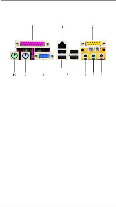
1.4 ASRock I/OTM
1 |
Parallel Port |
2 |
RJ-45 Port |
3 |
Game Port |
4 |
Microphone (Pink) |
5 |
Line In (Light Blue) |
6 |
Line Out (Lime) |
7 |
USB 2.0 Ports |
8 |
VGA Port |
9 |
PS/2 Keyboard Port (Purple) |
10 |
PS/2 Mouse Port (Green) |

 8
8
Chapter 2 Installation
M266A is a Micro ATX form factor (9.6" x 7.5", 24.4 x 19.1 cm) motherboard. Before you install the motherboard, study the configuration of your chassis to ensure that the motherboard fits into it.
Make sure to unplug the power cord before installing or removing the motherboard. Failure to do so may cause physical injuries to you and damages to motherboard components.
2.1 Screw Holes
Place screws into the holes indicated by circles to secure the motherboard to the chassis.
Do not over-tighten the screws! Doing so may damage the motherboard.
2.2 Pre-installation Precautions
Take note of the following precautions before you install motherboard components or change any motherboard settings.
1.Unplug the power cord from the wall socket before touching any component.
2.To avoid damaging the motherboard components due to static electricity, NEVER place your motherboard directly on the carpet or the like. Also remember to use a grounded wrist strap or touch a safety grounded object before you handle components.
3.Hold components by the edges and do not touch the ICs.
4.Whenever you uninstall any component, place it on a grounded antistatic pad or in the bag that comes with the component.
Before you install or remove any component, ensure that the power is switched off or the power cord is detached from the power supply. Failure to do so may cause severe damage to the motherboard, peripherals, and/or components.
9
 Loading...