


K7S8XE R3.0

1
K7S8X
K7S8XE
User Manual
Version 3.1
Published July 2003
Copyright©2003 ASRock INC. All rights reserved.

2
Copyright Notice:
No part of this manual may be reproduced, transcribed, transmitted, or translated in
any language, in any form or by any means, except duplication of documentation by
the purchaser for backup purpose, without written consent of ASRock Inc.
Products and corporate names appearing in this manual may or may not be regis-
tered trademarks or copyrights of their respective companies, and are used only for
identification or explanation and to the owners’ benefit, without intent to infringe.
Disclaimer:
Specifications and information contained in this manual are furnished for informa-
tional use only and subject to change without notice, and should not be constructed
as a commitment by ASRock. ASRock assumes no responsibility for any errors or
omissions that may appear in this manual.
With respect to the contents of this manual, ASRock does not provide warranty of
any kind, either expressed or implied, including but not limited to the implied warran-
ties or conditions of merchantability or fitness for a particular purpose.
In no event shall ASRock, its directors, officers, employees, or agents be liable for
any indirect, special, incidental, or consequential damages (including damages for
loss of profits, loss of business, loss of data, interruption of business and the like),
even if ASRock has been advised of the possibility of such damages arising from
any defect or error in the manual or product.
ASRock Website: http://www.asrock.com

3
Contents
1 Introduction.................................................... 4
1.1 Package Contents ........................................................... 4
1.2 Specifications ................................................................. 5
1.3 Motherboard Layout (K7S8X) ........................................ 7
1.4 Motherboard Layout (K7S8XE) ...................................... 8
1.5 ASRock I/O
TM
(K7S8X / K7S8XE) ................................... 9
2 Installation ...................................................... 10
2.1 Screw Holes ................................................................... 10
2.2 Pre-installation Precautions ............................................ 10
2.3 CPU Installation ............................................................... 11
2.4 Installation of Heatsink and CPU fan .............................. 11
2.5 Installation of Memory Modules (DIMM) .......................... 12
2.6 Expansion Slots .............................................................. 12
2.7 Jumpers Setup ................................................................ 13
2.8 Connectors ..................................................................... 15
3 BIOS Setup ...................................................... 17
3.1 BIOS Setup Utility ............................................................ 17
3.1.1 BIOS Menu Bar ..................................................... 17
3.1.2 Legend Bar ........................................................... 17
3.2 Main Menu ....................................................................... 18
3.3 Advanced, Security, Power, Boot, and Exit Menus ...... 20
4 Software Support ........................................... 21
4.1 Installing Operating System ............................................ 21
4.2 Support CD Information ................................................... 21
4.2.1 Running Support CD ............................................. 21
4.2.2 Drivers Menu ........................................................ 21
4.2.3 Utilities Menu ......................................................... 21
4.2.4 ASRock “PC-DIY Live Demo” Program ................. 21
4.2.5 Contact Information............................................... 21
Appendix ........................................................... 22
1. Advanced Menu ............................................................. 22
2. Security Menu ................................................................. 26
3. Power Menu ................................................................... 27
4. Boot Menu ....................................................................... 28
5. Exit Menu ......................................................................... 29
4
Chapter 1 Introduction
Thank you for purchasing ASRock K7S8X / K7S8XE motherboard, a reliable
motherboard produced under ASRock’s consistently stringent quality control. It de-
livers excellent performance with robust design conforming to ASRock’s commit-
ment to quality and endurance.
Chapter 1 and 2 of this manual contain introduction of the motherboard and step-by-
step installation guide for new DIY system builders. Chapter 3 and 4 contain basic
BIOS setup and support CD information. For advanced users’ reference, the Appen-
dix appearing on page 22 offers more advanced BIOS setup information.
Because the motherboard specifications and the BIOS software
might be updated, the content of this manual will be subject to
change without notice. In case any modifications of this manual
occur, the updated version will be available on ASRock website
without further notice. You may find the latest memory and CPU
support lists on ASRock website as well.
ASRock website http://www.asrock.com
1.1 Package Contents
ASRock K7S8X or K7S8XE motherboard
(ATX form factor: 12.0" x 7.5", 30.5 x 19.0 cm)
ASRock K7S8X / K7S8XE Quick Installation Guide
ASRock AMD-SiS Series Support CD
1 cable for IDE devices (1 x ATA 66/100/133)
1 cable for floppy drive (1 x ribbon cable)
1 ASRock I/O shield

5
1.2 Specifications
Platform: ATX form factor (12.0" x 7.5", 30.5 x 19.0 cm)
CPU: Supports Socket A (462 pins) for
AMD Athlon
TM
/ Athlon
TM
XP/ Duron
TM
processor
Chipsets: North Bridge (K7S8X):
SiS 746FX, FSB @ 333MHz, AGP 8X / 4X (see CAUTION 1);
North Bridge (K7S8XE):
SiS 748, FSB @ 400MHz, AGP 8X / 4X (see CAUTION 1);
South Bridge: SiS 963L, supports USB 2.0, ATA 133
Memory: 3 D DR DIMM slots: DDR1, DDR2, and DDR3
PC1600 (DDR200) / PC2100 (DDR266)
for 3 DDR DIMM slots, Max. 3GB;
PC2700 (DDR333) for 2 DDR DIMM slots, Max. 2GB;
PC3200 (DDR400) for 1 DDR DIMM slot, Max. 1GB
IDE: IDE1: ATA 133 / Ultra DMA Mode 6;
IDE2: ATA 133 / Ultra DMA Mode 6;
Can connect up to 4 IDE devices
Floppy Port: Supports 2 floppy disk drives
Audio: 5.1 channels AC’97 Audio
LAN: Speed: 802.3u (10/100 Ethernet), supports Wake-On-LAN
Hardware Monitor: CPU temperature sensing;
Chassis temperature sensing;
CPU overheat shutdown to protect CPU life
(ASRock U-COP)(see CAUTION 2);
Voltage monitoring: +12V, +5V, +3V, Vcore;
CPU fan tachometer; Chassis fan tachometer
PCI slots: 5 slots with PCI Specification 2.2
AGP slot: 1 AGP slot, supports 1.5V, 8X / 4X AGP card (see CAUTION 3)
USB 2.0: 4 default USB 2.0 ports and 1 extra set of header for two
additional USB 2.0 ports upgrade (see CAUTION 4)
ASRock I/O
TM
: PS/2: 1 keyboard port / 1 mouse port;
1 RJ 45 port; 4 rear default USB 2.0 ports;
1 serial port: COM 1; 1 parallel port: ECP/EPP support;
Audio Jack: Line Out/ Line In/ Microphone + Game port
BIOS: AMI legal BIOS; Supports “Plug and Play”;
ACPI 1.1 compliance wake up events;
SMBIOS 2.3.1 support;
CPU frequency stepless control
(only for advanced users’ reference, see CAUTION 5)
OS: Microsoft
®
Windows
®
98 SE / ME / 2000 / XP compliant

6
CAUTION!
1. According to SiS official document, SiS 746FX and SiS 748
chipsets have limitation as below:
SiS 746FX:
CPU at FSB 200MHz mode, it will not support DDR400;
CPU at FSB 333MHz mode, it will not support DDR200.
SiS 748:
CPU at FSB 200MHz mode, it will not support DDR400;
CPU at FSB 333MHz mode, it will not support DDR200;
CPU at FSB 400MHz mode, it will not support DDR200 / DDR266
2. While CPU overheat is detected, the system will automati-
cally shutdown. Please check if the CPU fan on the
motherboard functions properly before you resume the
system. To improve heat dissipation, remember to spray
thermal grease between the CPU and the heatsink when you
install the PC system.
3. Do NOT insert a 3.3V AGP card into the AGP slot of K7S8X or
K7S8XE motherboard! It may cause permanent damage!
4. Power Management for USB 2.0 works fine under Microsoft
®
Windows
®
XP. It may not work properly under Microsoft
®
Windows
®
98/ME/2000. Please refer to Microsoft
®
official
document at
http://www.microsoft.com/whdc/hwdev/bus/USB/USB2support.mspx
5. Although K7S8X / K7S8XE offers stepless control, it is not
recommended to perform over clocking. When the CPU
frequency of K7S8X / K7S8XE is set to perform over clocking,
other clocks, such as PCI clock, AGP clock, and Memory
clock will also be overclocked proportionally. Frequencies
other than the recommended CPU bus frequencies may
cause the instability of the system or damage the CPU.
7
PCI 2
PCI 3
PCI 4
PCI 5
PCI 1
2MB
BIOS
USB45
1
IR1
1
K7S8X
SPEAKER1
1
FLOPPY1
CHA_FAN1
ATXPWR1
IDE2
IDE1
ATA133
USB 2.05.1CH
REV. 3.01
Super
I/O
AUDIO
CODEC
LAN
PHY
AGP1
AGP 8X
DDR
4
00
CPU_FAN1
1
AUDIO1
Mic
In
GAME AUDIO1
USB 2.0
Ports
LAN
Micin
Lineout
GAME AUDIO1
PARALLEL PORT
PS/2
Mouse
PS/2
Keyboard
COM1
Line
In
Linein
USB2.0
Ports
FSB_SEL0
FSB_SEL1
1
1
SiS
963L
SiS
746FX
Chipset
PS2_USB_PWR1
1
10
DDR1 (64/72bit, 184-pin module)
32
DDR2 (64/72bit, 184-pin module)
DDR3 (64/72bit, 184-pin module)
45
CLRCMOS2
CMOS
Battery
HDLED RST
PLED PWRBTN
1
PANEL1
JR1
JL1
19.0cm (7.5 in)
30.5cm (12.0 in)
12 4
56
7
8
9
10
11
12
13
14
15
1617
18
19
20
21
22
23
24
25
26
27
28
29
3
1
1
1
1
1
FID0
FID1
FID2
FID3
FID4
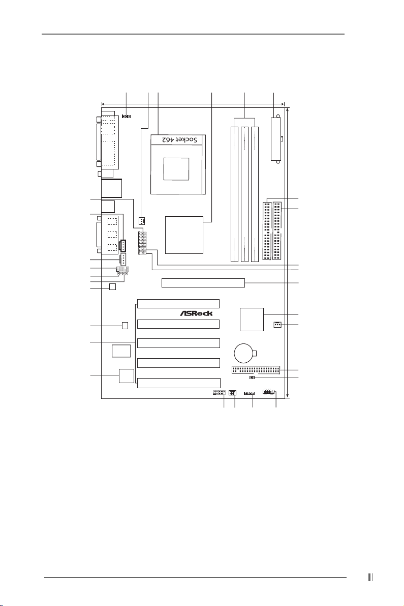
1.3 Motherboard Layout (K7S8X)
1 PS2_USB_PWR1 jumper 2 CPU fan connector (CPU_FAN1)
3 CPU socket 4 North Bridge controller
5 184-pin DDR DIMM slots (DDR 1- 3) 6 ATX power connector (ATXPWR1)
7 Secondary IDE connector (IDE2, Black) 8 Primary IDE connector (IDE1, Blue)
9 FSB select jumpers (FSB_SEL0) 10 FSB select jumpers (FSB_SEL1)
11 AGP slot (AGP1) 12 South Bridge controller
13 Chassis fan connector (CHA_FAN1) 14 Floppy connector (FLOPPY1)
15 Clear CMOS (CLRCMOS2, 2-pin jumper) 16 System panel connector (PANEL1)
17 External speaker connector (SPEAKER 1) 18 Infrared module connector (IR1)
19 USB 2.0 header (USB45, Blue) 20 Flash Memory
21 PCI slots (PCI 1- 5) 22 LAN PHY
23 AUDIO CODEC 24 JL1 jumper
25 JR1 jumper 26 Front panel audio connector (AUDIO1)
27 Internal audio connector: AUX1 (White) 28 Internal audio connector: CD1 (Black)
29 FID Jumpers (FID0, FID1, FID2, FID3, FID4)

8
1.4 Motherboard Layout (K7S8XE)
1 PS2_USB_PWR1 jumper 2 CPU fan connector (CPU_FAN1)
3 CPU socket 4 North Bridge controller
5 184-pin DDR DIMM slots (DDR 1- 3) 6 ATX power connector (ATXPWR1)
7 Secondary IDE connector (IDE2, Black) 8 Primary IDE connector (IDE1, Blue)
9 FSB select jumpers (FSB_SEL0) 10 FSB select jumpers (FSB_SEL1)
11 AGP slot (AGP1) 12 South Bridge controller
13 Chassis fan connector (CHA_FAN1) 14 Floppy connector (FLOPPY1)
15 Clear CMOS (CLRCMOS2, 2-pin jumper) 16 System panel connector (PANEL1)
17 External speaker connector (SPEAKER 1) 18 Infrared module connector (IR1)
19 USB 2.0 header (USB45, Blue) 20 Flash Memory
21 PCI slots (PCI 1- 5) 22 LAN PHY
23 AUDIO CODEC 24 JL1 jumper
25 JR1 jumper 26 Front panel audio connector (AUDIO1)
27 Internal audio connector: AUX1 (White) 28 Internal audio connector: CD1 (Black)
29 FID Jumpers (FID0, FID1, FID2, FID3, FID4)
PCI 2
PCI 3
PCI 4
PCI 5
PCI 1
2MB
BIOS
USB45
1
IR1
1
K7S8XE
SPEAKER1
1
FLOPPY1
CHA_FAN1
ATXPWR1
IDE2
IDE1
ATA133
USB 2.05.1CH
REV. 3.01
Super
I/O
AUDIO
CODEC
LAN
PHY
AGP1
AGP 8X
DDR
4
00
CPU_FAN1
1
AUDIO1
Mic
In
GAME AUDIO1
USB 2.0
Ports
LAN
Micin
Lineout
GAME AUDIO1
PARALLEL PORT
PS/2
Mouse
PS/2
Keyboard
COM1
Line
In
Linein
USB2.0
Ports
FSB_SEL0
FSB_SEL1
1
1
SiS
963L
SiS
748
Chipset
PS2_USB_PWR1
1
10
DDR1 (64/72bit, 184-pin module)
32
DDR2 (64/72bit, 184-pin module)
DDR3 (64/72bit, 184-pin module)
45
CLRCMOS2
CMOS
Battery
HDLED RST
PLED PWRBTN
1
PANEL1
JR1
JL1
19.0cm (7.5 in)
30.5cm (12.0 in)
12 4
56
7
8
9
10
11
12
13
14
15
1617
18
19
20
21
22
23
24
25
26
27
28
29
3
1
1
1
1
1
FID0
FID1
FID2
FID3
FID4
9
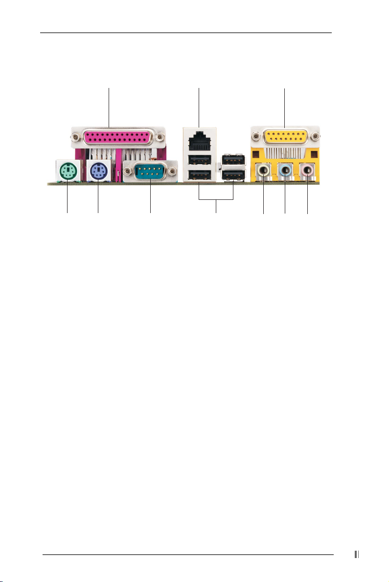
1.5 ASRock I/O
TM
(K7S8X / K7S8XE)
1 Parallel port 2 RJ-45 port
3 Game port 4 Microphone (Pink)
5 Line In (Light Blue) 6 Line Out (Lime)
7 USB 2.0 ports 8 Serial port (COM1)
9 PS/2 keyboard port (Purple) 10 PS/2 mouse port (Green)
12
3
4567
8
910
 Loading...