


J4105M
Table of contents
 Loading...

Version 1.0
Published November 2017
Copyright©2017 ASRock INC. All rights reserved.
Copyright Notice:
No part of this documentation may be reproduced, transcribed, transmitted, or
translated in any language, in any form or by any means, except duplication of
documentation by the purchaser for backup purpose, without written consent of
ASRock Inc.
Products and corporate names appearing in this documentation may or may not
be registered trademarks or copyrights of their respective companies, and are used
only for identication or explanation and to the owners’ benet, without intent to
infringe.
Disclaimer:
Specications and information contained in this documentation are furnished for
informational use only and subject to change without notice, and should not be
constructed as a commitment by ASRock. ASRock assumes no responsibility for
any errors or omissions that may appear in this documentation.
With respect to the contents of this documentation, ASRock does not provide
warranty of any kind, either expressed or implied, including but not limited to
the implied warranties or conditions of merchantability or tness for a particular
purpose.
In no event shall ASRock, its directors, ocers, employees, or agents be liable for
any indirect, special, incidental, or consequential damages (including damages for
loss of prots, loss of business, loss of data, interruption of business and the like),
even if ASRock has been advised of the possibility of such damages arising from any
defect or error in the documentation or product.
is device complies with Part 15 of the FCC Rules. Operation is subject to the following
two conditions:
(1) this device may not cause harmful interference, and
(2) this device must accept any interference received, including interference that
may cause undesired operation.
CALIFORNIA, USA ONLY
e Lithium battery adopted on this motherboard contains Perchlorate, a toxic substance
controlled in Perchlorate Best Management Practices (BMP) regulations passed by the
California Legislature. When you discard the Lithium battery in California, USA, please
follow the related regulations in advance.
“Perchlorate Material-special handling may apply, see www.dtsc.ca.gov/hazardouswaste/
perchlorate”
ASRock Website: http://www.asrock.com

AUSTRALIA ONLY
Our goods come with guarantees that cannot be excluded under the Australian Consumer
Law. You are entitled to a replacement or refund for a major failure and compensation for
any other reasonably foreseeable loss or damage caused by our goods. You are also entitled
to have the goods repaired or replaced if the goods fail to be of acceptable quality and the
failure does not amount to a major failure. If you require assistance please call ASRock Tel
: +886-2-28965588 ext.123 (Standard International call charges apply)
e terms HDMI™ and HDMI High-Denition Multimedia Interface, and the HDMI
logo are trademarks or registered trademarks of HDMI Licensing LLC in the United
States and other countries.

Contents
Chapter 1 Introduction 1
1.1 Package Contents 1
1.2 Specications 2
1.3 Motherboard Layout 5
1.4 I/O Panel 7
Chapter 2 Installation 9
2.1 Installing Memory Modules (DIMM) 10
2.2 Expansion Slots (PCI Express Slots) 12
2.3 Jumpers Setup 13
2.4 Onboard Headers and Connectors 14
2.5 Intel® CNVi (Integrated WiFi/BT) Installation Guide 18
Chapter 3 Software and Utilities Operation 20
3.1 Installing Drivers 20
3.2 ASRock Live Update & APP Shop 21
3.2.1 UI Overview 21
3.2.2 Apps 22
3.2.3 BIOS & Drivers 25
3.2.4 Setting 26
Chapter 4 UEFI SETUP UTILITY 27
4.1 Introduction 27
4.1.1 UEFI Menu Bar 27
4.1.2 Navigation Keys 28

4.2 Main Screen 29
4.3 Advanced Screen 30
4.3.1 CPU Conguration 31
4.3.2 Chipset Conguration 32
4.3.3 Storage Conguration 34
4.3.4 Super IO Conguration 35
4.3.5 ACPI Conguration 36
4.3.6 USB Conguration 38
4.4 Tools 39
4.5 Hardware Health Event Monitoring Screen 41
4.6 Security Screen 42
4.7 Boot Screen 43
4.8 Exit Screen 45
Chapter 1 Introduction
ank you for purchasing ASRock J4105M / J4005M motherboard, a reliable
motherboard produced under ASRock’s consistently stringent quality control.
It delivers excellent performance with robust design conforming to ASRock’s
commitment to quality and endurance.
In this manual, Chapter 1 and 2 contains the introduction of the motherboard
and step-by-step installation guides. Chapter 3 contains the operation guide of the
soware and utilities. Chapter 4 contains the conguration guide of the BIOS setup.
Becau se the motherboard specications and the BIOS soware might be updated, the
content of this documentation will be subject to change without notice. In case any
modications of this documentation occur, the updated version will be available on
ASRock’s website w ithout f urther notice. If you require technical support relate d to
this motherboard, please vi sit our website for s pecic information about the model
you are using. You may nd the l atest VGA cards and CPU suppor t list on ASRock’s
website a s well. ASRock website ht tp://www.a srock.com.
1.1 Package Contents
ASRock J4105M / J4005M Motherboard (Micro ATX Form Factor)
•
ASRock J4105M / J4005M Quick Installation Guide
•
ASRock J4105M / J4005M Support CD
•
2 x Serial ATA (SATA) Data Cables (Optional)
•
1 x Screw for M.2 Socket (Optional)
•
1 x I/O Panel Shield
•
J4105M
J4005M
English
1

1.2 Specications
Platform
CPU
Memory
Expansion
Slot
•
•
•
•
•
•
* 2GB DRAM per module is not supported.
•
•
* Intel® Extreme Memory Prole (XMP) is not supported
•
•
•
* M.2 PCI Express module is not supported
Micro ATX Form Factor
Solid Capacitor design
Intel® Quad-Core Processor J4105 (up to 2.5 GHz)
(for J4105M)
Intel® Dual-Core Processor J4005 (up to 2.7 GHz)
(for J4005M)
Dual Channel DDR4 Memory Technology
2 x DDR4 DIMM Slots
Supports DDR4 2400/2133 non-ECC, un-buered memory
Max. capacity of system memory: 8GB
1 x PCI Express 2.0 x16 Slot (PCIE2: x1 mode)
2 x PCI Express 2.0 x1 Slots
1 x M.2 Socket (Key E), supports type 2230 Intel® CNVi
(Integrated WiFi/BT)
English
2
Graphics
• Integrated Intel® UHD Graphics 600: 12 EUs inside (Up to
750MHz) (for J4105M)
• Integrated Intel® UHD Graphics 600: 12 EUs inside (Up to
700MHz) (for J4005M)
• DX12, OpenGL 4.3, OGL ES 3.0, OpenCL 2.0
• HW Acceleration Decode: HEVC (H.265) 8 bit, HEVC
(H.265)10 bit, H.264 @ Lvl5.2 (AVC), JPEG/MJPEG, VP8,
VP9 8bit, VP9 10 bit
• HW Acceleration Encode: HEVC (H.265) 8 bit, HEVC
(H.265)10 bit, H.264 @ Lvl5.2 (AVC), JPEG/MJPEG, VP8,
VP9 8bit
• ree graphics output options: D-Sub, DVI-D and HDMI
• Supports Triple Monitor
• Supports HDMI with max. resolution up to 4K x 2K
(4096x2160) @ 60Hz
• Supports DVI-D with max. resolution up to 1920x1200 @
60Hz

Audio
LAN
• Supports D-Sub with max. resolution up to 2048x1536 @
60Hz
• Supports Auto Lip Sync, xvYCC and HBR (High Bit Rate
Audio) with HDMI Port (Compliant HDMI monitor is
required)
• Supports HDCP with DVI-D and HDMI Ports
• Supports Full HD 1080p Blu-ray (BD) playback with DVI-D
and HDMI Ports
7.1 CH HD Audio (Realtek ALC887 Audio Codec)
•
* To congure 7.1 CH HD Audio, it is required to use an HD
front panel audio module and enable the multi-channel audio
feature through the audio driver.
Supports Surge Protection
•
ELNA Audio Caps
•
PCIE x1 Gigabit LAN 10/100/1000 Mb/s
•
Realtek RTL8111E
•
Supports Wake-On-LAN
•
Supports Lightning/ESD Protection
•
Supports Energy Ecient Ethernet 802.3az
•
Supports PXE
•
J4105M
J4005M
Rear Panel
I/O
Storage
1 x PS/2 Mouse Port
•
1 x PS/2 Keyboard Port
•
1 x D-Sub Port
•
1 x DVI-D Port
•
1 x HDMI Port
•
2 x USB 2.0 Ports (Supports ESD Protection)
•
2 x USB 3.1 Gen1 Ports (Supports ESD Protection)
•
1 x RJ-45 LAN Port with LED (ACT/LINK LED and SPEED
•
LED)
HD Audio Jacks: Line in / Front Speaker / Microphone
•
2 x SATA3 6.0 Gb/s Connectors, support NCQ, AHCI and
•
Hot Plug
English
3

Connector
BIOS
Feature
Hardware
Monitor
1 x Print Port Header
•
2 x COM Port Headers
•
1 x Chassis Intrusion and Speaker Header
•
1 x CPU Fan Connector (3-pin)
•
1 x Chassis Fan Connector (3-pin)
•
1 x 24 pin ATX Power Connector
•
1 x Front Panel Audio Connector
•
3 x USB 2.0 Headers (Support 5 USB 2.0 ports) (Supports ESD
•
Protection)
1 x USB 3.1 Gen1 Header (Supports 2 USB 3.1 Gen1 ports)
•
(Supports ESD Protection)
AMI UEFI Legal BIOS with GUI support
•
Supports Plug and Play
•
ACPI 5.0 compliant wake up events
•
Supports jumperfree
•
SMBIOS 3.0 support
•
CPU/Chassis temperature sensing
•
CPU/Chassis Fan Tachometer
•
CPU/Chassis Quiet Fan (Auto adjust chassis fan speed by
•
CPU temperature)
CPU/Chassis Fan multi-speed control
•
CASE OPEN detection
•
Voltage monitoring: +12V, +5V, +3.3V, CPU Vcore
•
English
4
Microso® Windows® 10 64-bit
OS
Certications
* For detailed product information, please visit our website: http://ww w.asrock.com
•
FCC, CE
•
ErP/EuP ready (ErP/EuP ready power supply is required)
•
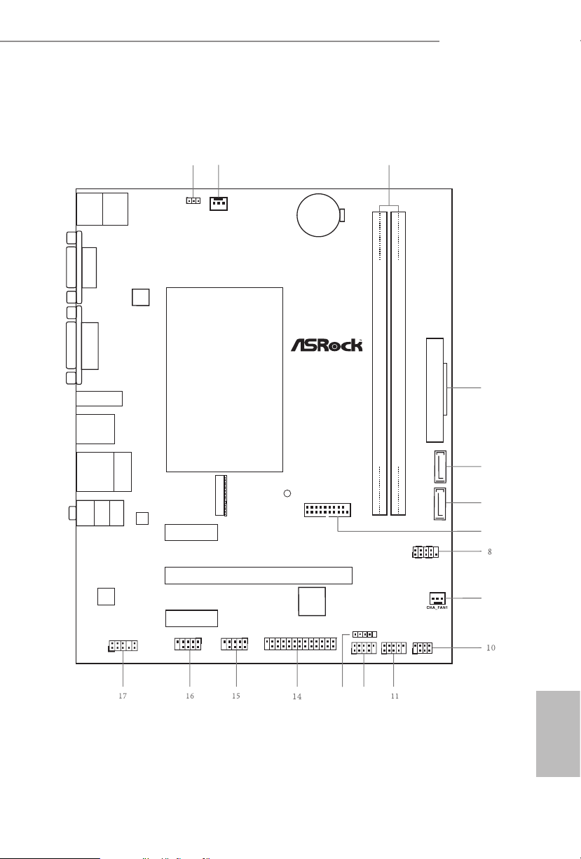
1.3 Motherboard Layout
PCIE 1
ATXP WR 1
13
12
AUDIO
CODEC
1
9
Sup er
I/O
3
PS2
Key boa rd
PS2
Mou se
CPU_FAN 1
1
USB_2_ 3
HDLED RESET
PLED PW RBTN
PANEL1
1
1
COM2
1
SATA3_2
CMO S
Bat te ry
Ro HS
1
HD_AU DIO1
2
4
5
6
7
BIOS
ROM
Fr on t US B 3 .0
LAN
CLRMOS1
1
USB3_ 1_2
SATA3_1
Top:
RJ-4 5
USB 2.0
T: US B0
B: USB1
Top:
LINE IN
Cente r:
FRONT
Botto m:
MIC IN
USB 3 .1 G en1
T: USB0
B: US B1
HDM I1
PCIE 2
PCIE 3
DVI 1
VGA 1
1
LPT1
DDR 4_A 2 ( 64 bit, 288 -pi n m od u le )
DDR 4_A 1 ( 64 bit, 288 -pi n m od u le )
COM1
1
1
USB_4_ 5
USB_6
SPK_CI1
1
CNV I1
CNVI1_CT 1
J4105M
J4005M
English
5

No. Description
1 Clear CMOS Jumper (CLRMOS1)
2 CPU Fan Connector (CPU_FAN1)
3 2 x 288-pin DDR4 DIMM Slots (DDR4_A1, DDR4_A2)
4 ATX Power Connector (ATXPWR1)
5 SATA3 Connector (SATA3_1)
6 SATA3 Connector (SATA3_2)
7 USB 3.1 Gen1 Header (USB3_1_2)
8 System Panel Header (PANEL1)
9 Chassis Fan Connector (CHA_FAN1)
10 Chassis Intrusion and Speaker Header (SPK_CI1)
11 USB 2.0 Header (USB_4_5)
12 USB 2.0 Header (USB_2_3)
13 USB 2.0 Header (USB_6)
14 Print Port Header (LPT1)
15 COM Port Header (COM1)
16 COM Port Header (COM2)
17 Front Panel Audio Header (HD_AUDIO1)
English
6
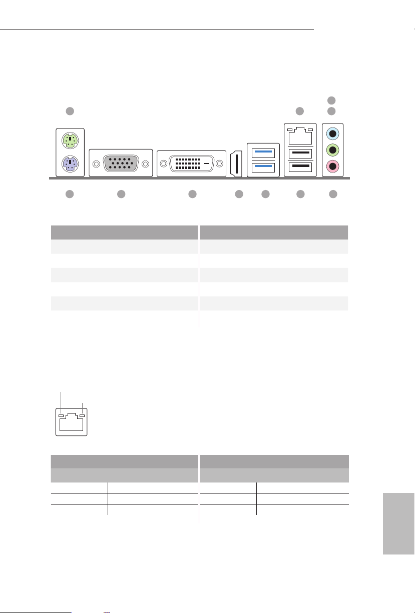
1.4 I/O Panel
1
J4105M
J4005M
3
2
4
10
No. Description No. Description
1 PS/2 Mouse Port 7 USB 3.1 Gen1 Ports (USB3_01)
2 LAN RJ-45 Port* 8 HDMI Port
3 Line In (Light Blue)** 9 DVI-D Port
4 Front Speaker (Lime)** 10 D-Sub Port
5 Microphone (Pink)** 11 PS/2 Keyboard Port
6 USB 2.0 Ports (USB01)
* ere are two LEDs on the LAN port. Please refer to the table below for the LAN port LED indications.
ACT/LINK L ED
SPEED LE D
LAN Por t
Activity / Link LED Speed LED
Status Description Status Description
O No Link O 10Mbps connection
Blinking Data Activity Orange 100Mbps connection
On Link Green 1Gbps connection
8 7
56911
English
7
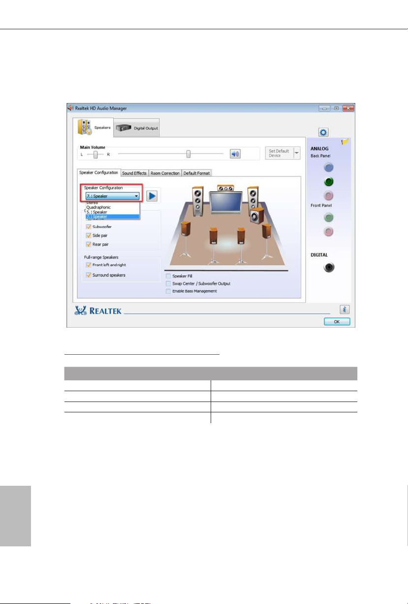
** To congure 7.1 CH HD Audio, it i s required to use an HD front panel audio module and enable the multichannel audio feature through the audio driver.
Please set Speaker Conguration to “7.1 Speaker”in the Realtek HD Audio Manager.
Function of the Audio Por ts in 7.1-channel Con guration:
English
8
Port Function
Light Blue (Rear panel) Rear Speaker Out
Lime (Rear panel) Front Speaker Out
Pink (Rear panel) Central /Subwoofer Speaker Out
Lime (Front panel) Side Speaker Out

Chapter 2 Installation
is is a Micro ATX form factor motherboard. Before you install the motherboard,
study the conguration of your chassis to ensure that the motherboard ts into it.
Pre-installation Precautions
Take note of the following precautions before you install motherboard components
or change any motherboard settings.
Make sure to unplug the power cord before installing or removing the motherboard.
•
Failure to do so may cause physical injuries to you and damages to motherboard
components.
In order to avoid damage from static electricity to the motherboard’s components,
•
NEVER place your motherboard directly on a carpet. Also remember to use a grounded
wrist strap or touch a safety grounded object before you handle the components.
Hold components by the edges and do not touch the ICs.
•
Whenever you uninstall any components, place them on a grounded anti-static pad or
•
in the bag that comes with the components.
When placing screws to secure the motherboard to the chassis, please do not over-
•
tighten the screws! Doing so may damage the motherboard.
J4105M
J4005M
English
9
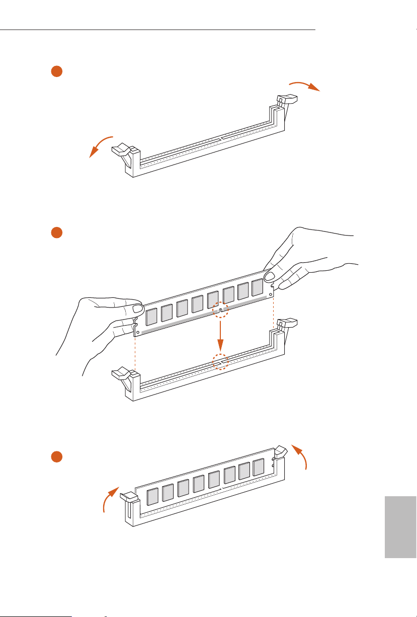
2.1 Installing Memory Modules (DIMM)
This motherboard provides two 288-pin DDR4 (Double Data Rate 4) DIMM slots, and
supports Dual Channel Memory Technology.
1. It is not allowed to install a DDR, DDR2 or DDR3 memory module into a DDR4
slot; otherwise, this motherboard and DIMM may be damaged.
2. e DI MM only ts in one correct orientation. It will cause per manent damage to
the mothe rboard and the DIMM if you force the DIMM into the slot at incor rect
orientation .
Supported DDR4 Non ECC DIMM
Raw Card
A (1Rx8)
B (2Rx8)
C (1Rx16)
Dual Channel Memory Conguration
English
10
DDR4_ A1
DDR4_ A2
Populated
Populated
J4105M
J4005M
1
2
3
English
11
Loading...