


FM2A68M-HD+
FM2A68M-HD+

Version 1.0
Published October 2014
Copyright©2014 ASRock INC. All rights reserved.
Copyright Notice:
No part of this documentation may be reproduced, transcribed, transmitted, or translated in any language, in any form or by any means, except duplication of documentation by the purchaser for backup purpose, without written consent of ASRock Inc.
Products and corporate names appearing in this documentation may or may not be registered trademarks or copyrights of their respective companies, and are used only for identification or explanation and to the owners’ benefit, without intent to
infringe.
Disclaimer:
Specifications and information contained in this documentation are furnished for informational use only and subject to change without notice, and should not be constructed as a commitment by ASRock. ASRock assumes no responsibility for any errors or omissions that may appear in this documentation.
With respect to the contents of this documentation, ASRock does not provide warranty of any kind, either expressed or implied, including but not limited to the implied warranties or conditions of merchantability or fitness for a particular purpose.
In no event shall ASRock, its directors, officers, employees, or agents be liable for any indirect, special, incidental, or consequential damages (including damages for loss of profits, loss of business, loss of data, interruption of business and the like), even if ASRock has been advised of the possibility of such damages arising from any defect or error in the documentation or product.
The terms HDMI™ and HDMI High-Definition Multimedia Interface, and the HDMI logo are trademarks or registered trademarks of HDMI Licensing LLC in the United States and other countries.
This device complies with Part 15 of the FCC Rules. Operation is subject to the following two conditions:
(1)this device may not cause harmful interference, and
(2)this device must accept any interference received, including interference that may cause undesired operation.
CALIFORNIA, USA ONLY
The Lithium battery adopted on this motherboard contains Perchlorate, a toxic substance controlled in Perchlorate Best Management Practices (BMP) regulations passed by the California Legislature. When you discard the Lithium battery in California, USA, please follow the related regulations in advance.
“Perchlorate Material-special handling may apply, see www.dtsc.ca.gov/hazardouswaste/perchlorate”
ASRock Website: http://www.asrock.com

AUSTRALIA ONLY
Our goods come with guarantees that cannot be excluded under the Australian Consumer Law. You are entitled to a replacement or refund for a major failure and compensation for any other reasonably foreseeable loss or damage caused by our goods. You are also entitled to have the goods repaired or replaced if the goods fail to be of acceptable quality and the failure does not amount to a major failure. If you require assistance please call ASRock Tel : +886-2-28965588 ext.123 (Standard International call charges apply)
The terms HDMI™ and HDMI High-Definition Multimedia Interface, and the HDMI logo are trademarks or registered trademarks of HDMI Licensing LLC in the United States and other countries.
Contents
1. |
Introduction |
1 |
1.1 |
Package Contents |
1 |
1.2 |
Specifications |
2 |
1.3 |
Motherboard Layout |
6 |
1.4 |
I/O Panel |
8 |
2. |
Installation |
9 |
2.1 |
CPU Installation |
10 |
2.2 |
Installation of CPU Fan and Heatsink |
11 |
2.3 |
Installation of Memory Modules (DIMM) |
12 |
2.4 |
Expansion Slots (PCI and PCI Express Slots) |
14 |
2.5 |
Jumpers Setup |
15 |
2.6 |
Onboard Headers and Connectors |
16 |
2.7 |
AMD Dual Graphics Operation Guide |
20 |
3. |
Software and Utilities Operation |
22 |
|
4. |
UEFI SETUP UTILITY |
38 |
|
4.1 |
|
Introduction |
38 |
4.1.1 |
UEFI Menu Bar |
38 |
|
4.1.2 |
Navigation Keys |
39 |
|
4.2 |
Main Screen |
39 |
|
4.3 |
OC Tweaker Screen |
40 |
|
4.4 |
Advanced Screen |
43 |
|
4.4.1 |
CPU Configuration |
44 |
|
4.4.2 |
North Bridge Configuration |
45 |
4.4.3 |
South Bridge Configuration |
46 |
4.4.4 |
Storage Configuration |
47 |
4.4.5 |
Super IO Configuration |
48 |
4.4.6 |
ACPI Configuration |
49 |
4.4.7 |
USB Configuration |
51 |
4.5 |
Tool |
53 |
4.6 |
Hardware Health Event Monitoring Screen |
56 |
4.7 |
Boot Screen |
57 |
4.8 |
Security Screen |
59 |
4.9 |
Exit Screen |
60 |

FM2A68M-HD+
1. Introduction
Thank you for purchasing ASRock FM2A68M-HD+ motherboard, a reliable motherboard produced under ASRock’s consistently stringent quality control. It delivers excellent performance with robust design conforming to ASRock’s commitment to quality and endurance.
In this documentation, Chapter 1 and 2 contains the introduction of the motherboard and step-by-step installation guides. Chapter 3 contains the operation guide of the software and utilities. Chapter 4 contains the configuration guide of the BIOS setup.
Because the motherboard specifications and the BIOS software might be updated, the content of this manual will be subject to change without notice. In case any modifications of this manual occur, the updated version will be available on ASRock website without further notice. You may find the latest VGA cards and CPU support lists on ASRock website as well. ASRock website http://www.asrock.com
If you require technical support related to this motherboard, please visit our website for specific information about the model you are using. www.asrock.com/support/index.asp
1.1 Package Contents
ASRock FM2A68M-HD+ Motherboard (Micro ATX Form Factor)
ASRock FM2A68M-HD+ Quick Installation Guide
ASRock FM2A68M-HD+ Support CD
2 x Serial ATA (SATA) Data Cables (Optional)
1 x I/O Panel Shield
English
1

English
1.2 Specifications
Platform |
• Micro ATX Form Factor |
|
• All Solid Capacitor design |
|
• High Density Glass Fabric PCB |
CPU |
• Supports Socket FM2+ 95W / FM2 100W processors |
Chipset |
• AMD A68H (Bolton-D2H) |
Memory |
• Dual Channel DDR3 Memory Technology |
|
• 2 x DDR3 DIMM Slots |
|
• Supports DDR3 2400+(OC)/2133(OC)/1866 |
|
(OC)/1600/1333/1066 non-ECC, un-buffered memory |
|
(see CAUTION 1) |
|
• Max. capacity of system memory: 32GB |
|
(see CAUTION 2) |
|
• Supports Intel® Extreme Memory Profile (XMP) 1.3 / 1.2 |
|
• Supports AMD Memory Profile Technology (AMP) up to |
|
AMP 2400 |
Expan- |
• 1 x PCI Express 3.0 x16 Slot (PCIE1@ x16 mode) |
sion |
* PCIE 3.0 is only supported with FM2+ CPU. With FM2 |
Slot |
CPU, it only supports PCIE 2.0. |
|
• 1 x PCI Express 2.0 x1 Slot |
|
• 1 x PCI Slot |
|
• Supports AMD Dual Graphics |
Graphics • Integrated AMD RadeonTM R7/R5 Series Graphics in A-series APU
•DirectX 11.1, Pixel Shader 5.0 with FM2+ CPU. DirectX 11, Pixel Shader 5.0 with FM2 CPU.
•Max. shared memory 2GB
•Three graphics output options: D-Sub, DVI-D and HDMI
Ports
•Supports Triple Monitor
•Supports HDMI with max. resolution up to 4K × 2K (4096x2160) @ 24Hz
*Only FM2+ APU can support up to 4096x2160 resolution display via HDMI port
2

FM2A68M-HD+
• Supports Dual-link DVI-D with max. resolution up to
2560x1600 @ 60Hz
• Supports D-Sub with max. resolution up to 1920x1200 @ 60Hz
• Supports Auto Lip Sync, Deep Color (12bpc), xvYCC and HBR (High Bit Rate Audio) with HDMI Port (Compliant HDMI monitor is required) (see CAUTION 3)
• Supports Blu-ray Stereoscopic 3D with HDMI Port
• Supports AMD Steady VideoTM 2.0: New video post
|
|
processing capability for automatic jitter reduction on |
|
|
home/online video |
|
• Supports HDCP with DVI-D and HDMI Ports |
|
|
• Supports Full HD 1080p Blu-ray (BD) playback with |
|
|
|
DVI-D and HDMI Ports |
Audio |
• |
5.1 CH HD Audio (Realtek ALC662 Audio Codec) |
|
• Supports Surge Protection (ASRock Full Spike Protec- |
|
|
|
tion) |
LAN |
• |
PCIE x1 Gigabit LAN 10/100/1000 Mb/s |
|
• |
Realtek RTL8111GR |
|
• Supports Wake-On-WAN |
|
|
• Supports Wake-On-LAN |
|
|
• Supports Lightning/ESD Protection (ASRock Full Spike |
|
|
|
Protection) |
|
• Supports LAN Cable Detection |
|
|
• Supports Energy Efficient Ethernet 802.3az |
|
|
• |
Supports PXE |
Rear |
• |
1 x PS/2 Mouse/Keyboard Port |
Panel I/O |
• |
1 x D-Sub Port |
• 1 x DVI-D Port
• 1 x HDMI Port
• 4 x USB 2.0 Ports (Supports ESD Protection (ASRock Full Spike Protection))
• 2 x USB 3.0 Ports (AMD A68H (Bolton-D2H)) (Supports ESD Protection (ASRock Full Spike Protection))
• 1 x RJ-45 LAN Port with LED (ACT/LINK LED and SPEED LED)
• HD Audio Jacks: Line in / Front Speaker / Microphone
English
3

Storage |
• |
4 x SATA3 6.0 Gb/s Connectors, support RAID (RAID 0, |
|
|
RAID 1 and RAID 10), NCQ, AHCI and Hot Plug |
Connec- |
• |
1 x Print Port Header |
tor |
• |
1 x COM Port Header |
|
• 1 x Chassis Intrusion Header |
|
|
• 1 x TPM Header |
|
|
• 1 x CPU Fan Connector (4-pin) |
|
|
• 1 x Chassis Fan Connector (4-pin) |
|
|
• 1 x Power Fan Connector (3-pin) |
|
|
• 1 x 24 pin ATX Power Connector |
|
|
• 1 x 4 pin 12V Power Connector |
|
|
• 1 x Front Panel Audio Connector |
|
|
• 2 x USB 2.0 Headers (Support 4 USB 2.0 ports) |
|
|
|
(Supports ESD Protection (ASRock Full Spike Protec- |
|
|
tion)) |
|
• 1 x USB 3.0 Header by ASMedia ASM1042A (Supports |
|
|
|
2 USB 3.0 ports) (Supports ESD Protection (ASRock |
|
|
Full Spike Protection)) |
BIOS |
• |
64Mb AMI UEFI Legal BIOS with GUI support |
Feature |
• |
Supports “Plug and Play” |
|
• ACPI 1.1 Compliant wake up events |
|
|
• |
Supports jumperfree |
|
• |
SMBIOS 2.3.1 support |
• DRAM, CPU Voltage multi-adjustment
Hardware • CPU temperature sensing
Monitor • Chassis temperature sensing
•CPU Fan Tachometer
•Chassis Fan Tachometer
•CPU/Chassis Quiet Fan
•CPU/Chassis Fan multi-speed control
•CASE OPEN detection
•Voltage monitoring: +12V, +5V, +3.3V, Vcore
English
4

FM2A68M-HD+
OS |
• Microsoft® Windows® 10 32-bit / 10 64-bit / 8.1 32-bit / 8.1 |
|
64-bit / 8 32-bit / 8 64-bit / 7 32-bit / 7 64-bit |
|
* For the updated Windows® 10 driver, please visit |
|
ASRock's website for details: http://www.asrock.com |
|
* Carrizo FM2r2 processor supports Windows® 10 64-bit/ |
|
8.1 64-bit / 7 32-bit / 7 64-bit only. |
Certifica- |
• FCC, CE, WHQL |
tions |
• ErP/EuP Ready (ErP/EuP ready power supply is re- |
|
quired) |
* For detailed product information, please visit our website: http://www.asrock.com
WARNING
Please realize that there is a certain risk involved with overclocking, including adjusting the setting in the BIOS, applying Untied Overclocking Technology, or using third-party overclocking tools. Overclocking may affect your system’s stability, or even cause damage to the components and devices of your system. It should be done at your own risk and expense. We are not responsible for possible damage caused by overclocking.
CAUTION!
1.Whether 2400/2133/1866/1600MHz memory speed is supported depends on the CPU you adopt. If you want to adopt DDR3 2400/2133/1866/1600 memory module on this motherboard, please refer to the memory support list on our website for the compatible memory modules.
ASRock website http://www.asrock.com
2.Due to the operating system limitation, the actual memory size may be less than 4GB for the reservation for system usage under Windows® 10 / 8.1 / 8 / 7. For Windows® 64-bit OS with 64bit CPU, there is no such limitation. You can use ASRock XFast RAM to utilize the memory that Windows® cannot use.
3.xvYCC and Deep Color are only supported under Windows® 10 64-bit / 10 / 8.1 64-bit / 8.1 / 8 64-bit / 8 / 7 64-bit / 7. Deep
Color mode will be enabled only if the display supports 12bpc in EDID. HBR is supported under Windows® 10 64-bit / 10 / 8.1 64-bit / 8.1 / 8 64-bit / 8 / 7 64-bit / 7.
English
5
1.3 Motherboard Layout
/Mous Keyboard PS2 e |
B:USB T:USB USB 2 1 2.0 |
|
|
DVI1
PWR_FAN1
VGA1
USB 3.0
T: USB3
B: USB4
HDMI1
USB 2.0 |
RJ- |
T: USB5 |
45 |
B: USB6 |
LA |
|
N |
|
|
HD_AUDIO1

 1
1
CI1
1 


English
CPU_FAN1
FM2b SOCKET

FM2A68M-HD+
PCIE1
64Mb BIOS
|
|
|
TPMS1 |
|
|
|
1 |
|
240-pinmodule) |
240-pinmodule) |
ATXPWR1 |
|
(64bit, |
(64bit, |
|
Express3.0 |
DDR3 A1 |
DDR3 B1 |
USB 11 12 |
|
|
|
1 |
PCI |
|
|
|
CHA_FAN1 |
|
2 |
4 |
|
SATA |
SATA |
|
|
|
||
|
|
1SATA |
3SATA |
AMD
A68H (Bolton-D2H) Chipset
USB_7_8 USB_9_10
6

FM2A68M-HD+
No. Description
1ATX 12V Power Connector (ATX12V1)
2CPU Fan Connector (CPU_FAN1)
32 x 240-pin DDR3 DIMM Slots (DDR3_A1, DDR3_B1)
4TPM Header (TPMS1)
5ATX Power Connector (ATXPWR1)
6USB 3.0 Header (USB_11_12)
7SATA3 Connector (SATA_2)
8SATA3 Connector (SATA_4)
9SATA3 Connector (SATA_3)
10SATA3 Connector (SATA_1)
11Chassis Speaker Header (SPEAKER1)
12System Panel Header (PANEL1)
13USB 2.0 Header (USB_9_10)
14USB 2.0 Header (USB_7_8)
15Chassis Fan Connector (CHA_FAN1)
16Clear CMOS Jumper (CLRCMOS1)
17Print Port Header (LPT1)
18COM Port Header (COM1)
19Chassis Intrusion Header (CI1)
20Front Panel Audio Header (HD_AUDIO1)
21Power Fan Connector (PWR_FAN1)
English
7
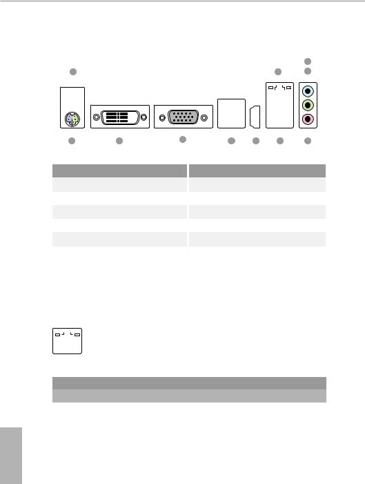
1.4 I/O Panel
|
|
|
|
|
|
|
|
|
|
|
|
|
|
|
|
|
|
|
|
|
3 |
|
1 |
|
|
|
|
|
|
|
|
|
2 |
|
|
|
4 |
||||||
|
|
|
|
|
|
|
|
|
|
|
|
|
|
|
|
|
|
|
|
|
|
|
|
|
|
|
|
|
|
|
|
|
|
|
|
|
|
|
|
|
|
|
|
|
|
|
|
|
|
|
|
|
|
|
|
|
|
|
|
|
|
|
|
|
|
|
|
|
|
|
|
|
|
|
|
|
|
|
|
|
|
|
|
|
|
|
|
|
|
|
|
|
|
|
|
|
|
|
|
|
|
|
|
|
|
|
|
|
|
|
|
|
|
|
|
|
|
|
|
|
|
|
|
|
|
|
|
|
|
|
|
|
|
|
|
|
|
|
|
|
|
|
|
|
|
|
|
|
|
|
|
|
|
|
|
|
|
|
|
|
|
|
|
|
|
|
|
|
|
|
|
|
|
|
|
|
|
|
|
|
|
|
|
|
|
|
|
|
|
|
|
|
|
|
|
|
|
|
|
|
|
|
|
|
|
|
|
|
|
|
|
|
|
|
|
|
|
|
|
|
|
|
|
|
|
|
|
|
|
|
|
|
|
|
|
|
|
|
|
|
|
|
|
|
|
|
|
|
|
|
|
|
|
|
|
|
|
|
|
|
|
|
|
11 10 9 8 7 6 5
No. |
Description |
No. |
Description |
1 |
USB 2.0 Ports (USB_1_2) |
7 |
HDMI Port |
2 |
LAN RJ-45 Port* |
8 |
USB 3.0 Ports (USB_3_4) |
3 |
Line In (Light Blue) |
9 |
D-Sub Port |
4 |
Front Speaker (Lime) |
10 |
DVI-D Port |
5 |
Microphone (Pink) |
11 |
PS/2 Mouse/Keyboard Port |
6USB 2.0 Ports (USB_5_6)
*There are two LEDs on the LAN port. Please refer to the table below for the LAN port LED indications.
ACT/LINK LED
|
|
SPEED LED |
|
|
|
|
|
|
|||
|
|
|
|
|
|
|
|
|
|
|
|
|
|
|
|
|
|
|
|
|
|
|
|
|
|
|
|
|
|
|
|
|
|
|
|
|
|
|
|
|
|
|
|
|
|||
|
LAN Port |
|
|
|
|
|
|
||||
Activity / Link LED |
|
Speed LED |
|
|
|||||||
|
|
|
|||||||||
Status |
|
Description |
|
Status |
|
Description |
|||||
Off |
|
No Link |
|
Off |
|
10Mbps connection |
|||||
|
|
|
|||||||||
Blinking |
|
Data Activity |
|
Orange |
|
100Mbps connection |
|||||
On |
|
Link |
|
Green |
|
1Gbps connection |
|||||
|
|
|
|
|
|
|
|
|
|
|
|
English
8
FM2A68M-HD+
2. Installation
This is a Micro ATX form factor motherboard. Before you install the motherboard, study the configuration of your chassis to ensure that the motherboard fits into it.
Pre-installation Precautions
Take note of the following precautions before you install motherboard components or change any motherboard settings.
Before you install or remove any component, ensure that the power is switched off or the power cord is detached from the power supply. Failure to do so may cause severe damage to the motherboard, peripherals, and/or components.
1.Unplug the power cord from the wall socket before touching any component.
2.To avoid damaging the motherboard components due to static electricity, NEVER place your motherboard directly on the carpet or the like. Also remember to use a grounded wrist strap or touch a safety grounded object before you handle components.
3.Hold components by the edges and do not touch the ICs.
4.Whenever you uninstall any component, place it on a grounded antistatic pad or in the bag that comes with the component.
5.When placing screws into the screw holes to secure the motherboard to the chassis, please do not over-tighten the screws! Doing so may damage the motherboard.
English
9
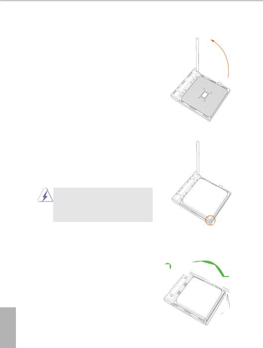
2.1 CPU Installation
Step 1. Unlock the socket by lifting the lever up to a 90o angle.
Step 2. Position the CPU directly above the socket such that the CPU corner with the golden triangle matches the socket corner with a small triangle.
Step 3. Carefully insert the CPU into the socket until it fits in place.
The CPU fits only in one correct orientation. DO NOT force the CPU into the socket to avoid bending of the pins.
Step 4. When the CPU is in place, press it firmly on the socket while you push down the socket lever to secure the CPU. The lever clicks on the side tab to indicate that it is locked.
English
10

FM2A68M-HD+
2.2 Installation of CPU Fan and Heatsink
After you install the CPU into this motherboard, it is necessary to install a larger heatsink and cooling fan to dissipate heat. You also need to spray thermal grease between the CPU and the heatsink to improve heat dissipation. Make sure that the CPU and the heatsink are securely fastened and in good contact with each other. Then connect the CPU fan to the CPU FAN connector (CPU_FAN1, see Page 6, No. 2). For proper installation, please kindly refer to the instruction manuals of the CPU fan and the heatsink.
English
11
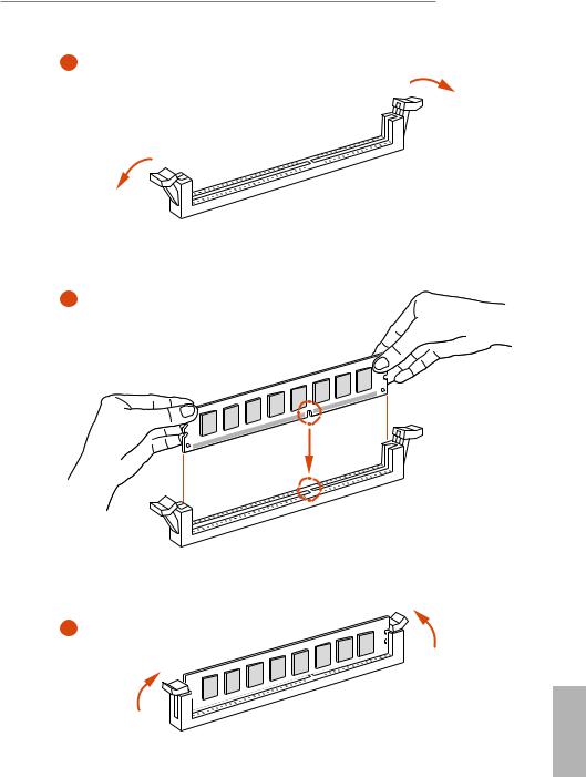
2.3 Installation of Memory Modules (DIMM)
This motherboard provides two 240-pin DDR3 (Double Data Rate 3) DIMM slots, and supports Dual Channel Memory Technology.
1.For dual channel configuration, you always need to install identical (the same brand, speed, size and chip-type) DDR3 DIMM pairs.
2.It is unable to activate Dual Channel Memory Technology with only one memory module installed.
3.It is not allowed to install a DDR or DDR2 memory module into a DDR3 slot; otherwise, this motherboard and DIMM may be damaged.
The DIMM only fits in one correct orientation. It will cause permanent damage to the motherboard and the DIMM if you force the DIMM into the slot at incorrect orientation.
English
12
FM2A68M-HD+
1
2
3
English
13

2.4 Expansion Slots (PCI and PCI Express Slots)
There are 1 PCI slot and 2 PCI Express slots on this motherboard.
Before installing an expansion card, please make sure that the power supply is switched off or the power cord is unplugged. Please read the documentation of the expansion card and make necessary hardware settings for the card before you start the installation.
PCI Slot: PCI slot is used to install expansion cards that have the 32-bit PCI interface.
PCIE Slots:
PCIE1 (PCIe 3.0 x16 slot) is used for PCI Express x16 lane width graphics cards.
PCIE2 (PCIe 2.0 x1 slot) is used for PCI Express cards with x1 lane width cards.
English
14
FM2A68M-HD+
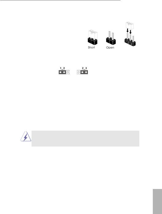
2.5 Jumpers Setup
The illustration shows how jumpers are setup. When the jumper cap is placed on pins, the jumper is “Short”. If no jumper cap is placed on pins, the jumper is “Open”. The illustration shows a 3-pin jumper whose pin1 and pin2 are “Short” when jumper cap is placed on these 2 pins.
Jumper |
Setting |
Description |
Clear CMOS Jumper |
|
|
(CLRCMOS1) |
|
|
(see p.6, No. 16) |
Default |
Clear CMOS |
|
Note: CLRCMOS1 allows you to clear the data in CMOS. To clear and reset the system parameters to default setup, please turn off the computer and unplug the power cord from the power supply. After waiting for 15 seconds, use a jumper cap to short pin2 and pin3 on CLRCMOS1 for 5 seconds. However, please do not clear the CMOS right after you update the BIOS. If you need to clear the CMOS when you just finish updating the BIOS, you must boot up the system first, and then shut it down before you do the clear-CMOS action. Please be noted that the password, date, time, user default profile, 1394
GUID and MAC address will be cleared only if the CMOS battery is removed.
If you clear the CMOS, the case open may be detected. Please adjust the BIOS option “Clear Status” to clear the record of previous chassis intrusion status.
English
15
 Loading...