


 Loading...

Version 1.0
Published December 2018
This device complies with Part 15 of the FCC Rules. Operation is subject to the following two conditions:
(1)this device may not cause harmful interference, and
(2)this device must accept any interference received, including interference that may cause undesired operation.
CALIFORNIA, USA ONLY
The Lithium battery adopted on this motherboard contains Perchlorate, a toxic substance controlled in Perchlorate Best Management Practices (BMP) regulations passed by the California Legislature. When you discard the Lithium battery in California, USA, please follow the related regulations in advance.
“Perchlorate Material-special handling may apply, see www.dtsc.ca.gov/hazardouswaste/ perchlorate”

AUSTRALIA ONLY
Our goods come with guarantees that cannot be excluded under the Australian Consumer Law. You are entitled to a replacement or refund for a major failure and compensation for any other reasonably foreseeable loss or damage caused by our goods. You are also entitled to have the goods repaired or replaced if the goods fail to be of acceptable quality and the failure does not amount to a major failure.
The terms HDMI™ and HDMI High-Definition Multimedia Interface, and the HDMI logo are trademarks or registered trademarks of HDMI Licensing LLC in the United States and other countries.
Contents
Chapter 1 Introduction |
1 |
|
1.1 |
Package Contents |
1 |
1.2 |
Specifications |
2 |
1.3 |
Motherboard Layout |
6 |
1.4 |
Front Panel |
9 |
1.5 |
Rear Panel |
10 |
Chapter 2 Installation |
11 |
|
2.1 |
Installing the CPU |
12 |
2.2 |
Installing the CPU Fan and Heatsink |
14 |
2.3 |
Installing Memory Modules (SO-DIMM) |
19 |
2.4 |
Jumpers Setup |
21 |
2.5 |
Onboard Headers and Connectors |
22 |
2.6 |
M.2 WiFi/BT Module Installation Guide |
25 |
2.7 |
M.2_SSD (NGFF) Module Installation Guide |
27 |
Chapter 3 Software and Utilities Operation |
29 |
|
3.1 |
Installing Drivers |
29 |
Chapter 4 UEFI SETUP UTILITY |
30 |
|
4.1 |
Introduction |
30 |
4.1.1 |
UEFI Menu Bar |
30 |
4.1.2 |
Navigation Keys |
31 |
4.2 |
Main Screen |
32 |
4.3 |
OC Tweaker Screen |
33 |
4.4 |
Advanced Screen |
35 |
4.4.1 |
CPU Configuration |
36 |
4.4.2 |
North Bridge Configuration |
37 |
4.4.3 |
South Bridge Configuration |
38 |
4.4.4 |
Storage Configuration |
39 |
4.4.5 |
ACPI Configuration |
40 |
4.4.6 |
AMD CBS |
41 |
4.4.7 |
AMD PBS |
42 |
4.5 |
Tools |
43 |
4.6 |
Hardware Health Event Monitoring Screen |
45 |
4.7 |
Security Screen |
46 |
4.8 |
Boot Screen |
47 |
4.9 |
Exit Screen |
49 |
A300M-STX
Chapter 1 Introduction
Thank you for purchasing A300M-STX motherboard. In this documentation, Chapter 1 and 2 contains the introduction of the motherboard and step-by-step installation guides. Chapter 3 contains the operation guide of the software and utilities. Chapter 4 contains the configuration guide of the BIOS setup.
Because the motherboard specifications and the BIOS software might be updated, the content of this documentation will be subject to change without notice.
1.1 Package Contents
•A300M-STX Motherboard (Mini-STX Form Factor)
•A300M-STX Quick Installation Guide
•A300M-STX Support CD
•1 x I/O Panel Shield
•2 x Serial ATA(SATA) Data with Power Cable (Optional)
•2 x Screws for M.2 Sockets (M2*2) (Optional)
•1 x Screw for WiFi Module (M2*2) (Optional)
English
1

English
1.2 Specifications
Platform |
• |
Mini-STX Form Factor |
|
• |
Solid Capacitor design |
CPU |
• |
Supports AMD Socket AM4 A-Series APUs (Bristol Ridge) |
|
|
and Ryzen Series CPUs (Raven Ridge) |
|
• Supports CPU up to 65W |
|
|
• 5 Power Phase design |
|
Chipset |
• |
AMD A300 |
Memory |
• |
Dual Channel DDR4 Memory Technology |
•2 x DDR4 SO-DIMM Slots
•AMD Ryzen series CPUs (Raven Ridge) support DDR4 2933/2667/2400/2133 non-ECC, un-buffered memory*
•AMD 7th Gen A-Series APUs support DDR4 2400/2133 nonECC, un-buffered memory*
*Please refer to page 19 for DDR4 SO-DIMM maximum frequency support.
•Max. capacity of system memory: 32GB
•15μ Gold Contact in SO-DIMM Slots
Expansion |
• |
1 x M.2 Socket (Key E), supports type 2230 WiFi/BT module |
|
Slot |
|||
|
|
||
Graphics |
• |
Integrated AMD RadeonTM Vega Series Graphics in Ryzen |
|
|
|
Series APU* |
•Integrated AMD RadeonTM R-Series Graphics in A-series APU*
*Actual support may vary by CPU
•DirectX 12, Pixel Shader 5.0
•Shared memory default 2GB. Max Shared memory supports up to 16GB.
*The Max shared memory 16GB requires 32GB system memory installed.
2

A300M-STX
|
• Three graphics output options: D-Sub, DisplayPort 1.2 and |
|
|
|
HDMI |
|
• |
Supports Triple Monitor |
|
• Supports HDMI with max. resolution up to 4K x 2K |
|
|
|
(4096x2160) @ 60Hz |
|
• Supports D-Sub with max. resolution up to 1920x1200 @ |
|
|
|
60Hz |
|
• Supports DisplayPort 1.2 with max. resolution up to 4K x 2K |
|
|
|
(4096x2304) @ 60Hz |
|
• Supports Auto Lip Sync, Deep Color (12bpc), xvYCC and HBR |
|
|
|
(High Bit Rate Audio) with HDMI Port (Compliant HDMI |
|
|
monitor is required) |
|
• Supports HDCP with HDMI and DisplayPort 1.2 Ports |
|
|
• Supports 4K Ultra HD (UHD) playback with HDMI and |
|
|
|
DisplayPort 1.2 Ports |
Audio |
• |
Realtek ALC233 Audio Codec |
|
• 1 x Headphone/Headset Jack |
|
|
• |
1 x MIC-In |
|
• 1 x Audio Header |
|
LAN |
• |
PCIE x1 Gigabit LAN 10/100/1000 Mb/s |
|
• |
Realtek RTL8111H |
|
• Supports Wake-On-LAN |
|
|
• |
Supports Lightning/ESD Protection |
|
• Supports Energy Efficient Ethernet 802.3az |
|
|
• |
Supports PXE |
Front |
• |
1 x Headphone/Headset Jack |
Panel I/O |
• |
1 x USB 3.1 Gen1 Type-A Port (Supports ESD Protection (Full |
|
|
Spike Protection)) |
• 1 x USB 3.1 Gen1 Type-C Port (Supports ESD Protection (Full
Spike Protection))
• 1 x Microphone Input Jack
English
3

Rear Panel |
• |
1 x DC Jack (Compatible with the 19V power adapter)* |
I/O |
* Please use 120W power adapter for 65W CPU and 90W power |
|
|
adapter for 35W CPU. |
|
|
• 1 x D-Sub Port |
|
|
• 1 x HDMI Port |
|
|
• 1 x DisplayPort 1.2 |
|
|
• 1 x USB 2.0 Port (Supports ESD Protection) |
|
|
• 1 x USB 3.1 Gen1 Port (Supports ESD Protection) |
|
|
• 1 x RJ-45 LAN Port with LED (ACT/LINK LED and SPEED |
|
|
|
LED) |
Storage |
• |
2 x SATA3 6.0 Gb/s with Power Connectors, support RAID |
|
|
(RAID 0 and RAID 1), NCQ, AHCI and Hot Plug |
|
• 1 x Ultra M.2 Socket (M2_1), supports type 2280 M.2 PCI |
|
|
|
Express module up to Gen3 x4 (32 Gb/s) |
|
• 1 x Ultra M.2 Socket (M2_2), supports type 2280 M.2 PCI |
|
|
|
Express module up to Gen3 x4 (32 Gb/s) (with A-Series APU |
|
|
and Raven Ridge) or Gen3 x2 (16 Gb/s) (with Athlon 2xxGE |
|
|
series)* |
|
* Supports NVMe SSD as boot disks |
|
Connector |
• |
1 x Chassis Intrusion Header |
|
• 2 x CPU Fan Connectors (2 x 4-pin) |
|
|
• 1 x Front Panel Header |
|
|
• 1 x USB 2.0 Header (Supports 2 USB 2.0 ports) (Supports ESD |
|
|
|
Protection) |
|
• 1 x Audio Header |
|
BIOS |
• |
AMI UEFI Legal BIOS with GUI support |
Feature |
• |
Supports "Plug and Play" |
|
• ACPI 5.1 compliance wake up events |
|
|
• |
Supports jumperfree |
|
• |
SMBIOS 2.3 support |
|
• |
DRAM Voltage adjustment |
English
4

A300M-STX
Hardware |
• |
CPU Temperature Sensing |
Monitor |
• |
CPU Fan Tachometer |
|
• CPU Quiet Fan (Auto adjust chassis fan speed by CPU |
|
|
|
temperature) |
|
• CPU Fan Multi-Speed Control |
|
|
• |
CASE OPEN detection |
|
• Voltage monitoring: +12V, +5V, +3.3V, CPU Vcore |
|
OS |
• |
Microsoft® Windows® 10 64-bit |
Certifica- |
• |
FCC, CE |
tions |
• |
ErP/EuP ready (ErP/EuP ready power supply is required) |
Please realize that there is a certain risk involved with overclocking, including adjusting the setting in the BIOS, applying Untied Overclocking Technology, or using third-party overclocking tools. Overclocking may affect your system’s stability, or even cause damage to the components and devices of your system. It should be done at your own risk and expense. We are not responsible for possible damage caused by overclocking.
Mini-STX Chassis Support List
Vendor |
Model |
SilverStone Technology Inc. |
VT01S |
AKasa |
A-STX04-A1B / A-STX04-M1B |
English
5
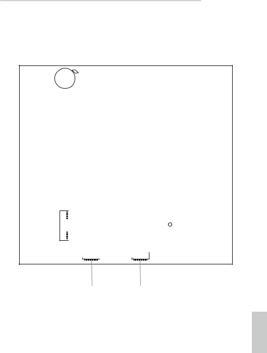
1.3 Motherboard Layout
1
Super
I/O
DC Jack
1DP
1HDMI
SOCKET AM4
|
|
USB_4_5 |
|
|||||||||
1 |
|
|
|
CLRMOS1 |
2 |
|||||||
|
|
|
1 |
|
|
|
|
|||||
SPEAKER1 |
|
|
|
|
|
|
|
CI1 |
3 |
|||
|
|
|
|
|
|
|
|
|
|
|
|
|
|
|
|
M.2 PCIe SSD |
|
|
|||||||
|
|
|
|
|
|
|
|
|
|
|
|
4 |
|
|
|
|
|
|
|
|
|
|
|
|
|
M.2 WiFi
|
|
|
|
|
|
|
|
Mic In |
|
VGA1 |
|
|
RoHS |
|
|
||
|
|
|
USB_TC_1 |
|||||
|
|
|
|
|
|
USB 3.1 Gen1 |
||
|
|
|
|
|
A300M-STX |
|
|
|
|
|
|
|
|
|
|
||
|
|
|
|
|
|
|
|
|
|
|
|
|
|
|
|
USB 3.1 Gen1 |
|
|
|
|
|
|
|
|
||
|
USB3 USB: 3 |
USB2 UST: 2.B |
|
|
DDR4_A1 |
|
|
USB_1 |
|
Top: |
|
|
|
|
|
||
|
|
|
|
|
||||
|
.Gen1 |
0 |
RJ-45 |
|
|
|
|
|
|
|
|
|
|
DDR4_B1 |
|
Headphone |
|
|
|
|
|
|
|
|
|
/ Headset |
|
|
|
|
|
|
|
|
|
|
|
|
Audio |
|
|
PANEL1 |
CODEC |
CPU_FAN2 CPU_FAN1 |
|
PLED PWRBTN |
|
BIOS |
|
|
AUDIO3 |
ROM |
|
|
1 |
|
1 |
|
|
|
|
|
|
|
|
HDLED RESET |
|
5
9 |
8 |
7 |
6 |
English
6
Back Side View
CMOS
Battery

 2_M2
2_M2
SATA3 |
|
SATA3 |
|
|
|
10 |
11 |
A300M-STX
CT1
English
7

No. Description
1USB 2.0 Header (USB_4_5)
2Clear CMOS Jumper (CLRCMOS1)
3Chassis Intrusion Header (CI1)
4Internal Speaker Header (SPEAKER1)
52 x 260-pin DDR4 SO-DIMM Slots (DDR4_A1, DDR4_B1)
6Audio Header (AUDIO3)
7System Panel Header (PANEL1)
8CPU Fan Connector (CPU_FAN1)
9CPU Fan Connector (CPU_FAN2)
10SATA3 Connector (SATA2)
11SATA3 Connector (SATA1)
English
8
A300M-STX
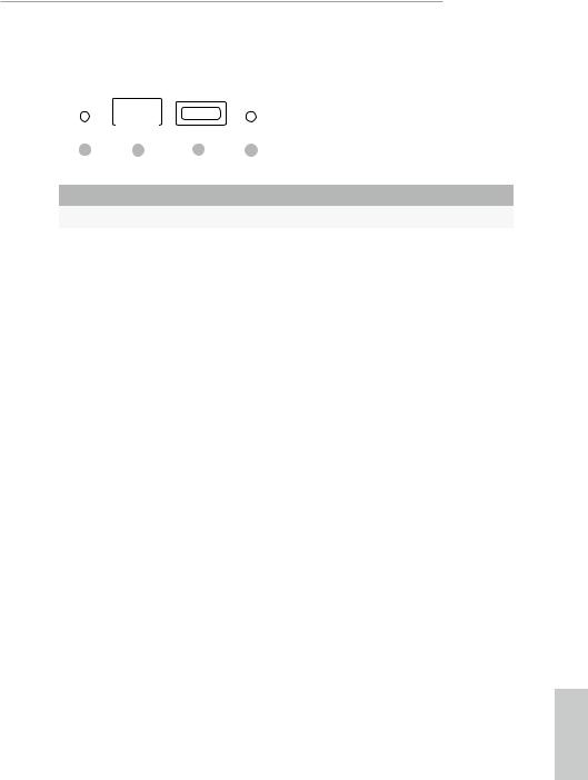
1.4 Front Panel
|
|
|
|
|
|
|
|
|
|
|
|
|
|
|
|
|
|
|
|
|
|
|
|
|
|
|
|
|
|
|
|
|
|
|
|
|
|
|
|
|
|
|
|
|
1 |
2 |
|
|
3 |
|
4 |
|
|
|
|
||||
No. |
Description |
|
|
|
|
No. |
Description |
|||||||
|
|
|
|
|||||||||||
1 |
|
Headphone/Headset Jack (AUDIO1) |
3 |
USB 3.1 Gen1 Type-C Port (USB_TC_1) |
||||||||||
2 |
|
USB 3.1 Gen1 Type-A Port (USB_1) |
4 |
Microphone Input (AUDIO2) |
||||||||||
|
|
|
|
|
|
|
|
|
|
|
|
|
|
|
English
9
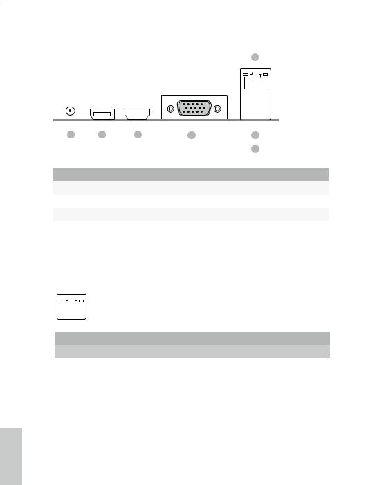
1.5 Rear Panel
7
|
|
|
|
|
|
|
|
|
|
|
|
|
|
|
|
|
|
|
|
|
|
|
|
|
|
|
|
|
|
|
|
|
|
|
|
|
|
|
|
|
|
|
|
|
|
|
|
|
|
|
|
|
|
|
|
|
|
|
|
|
|
|
|
|
|
|
|
|
|
1 |
2 |
3 |
|
4 |
|
5 |
|
|
|||||
|
|
|
|
|
|
|
|
6 |
|
|
|||
No. |
Description |
|
|
|
No. |
Description |
|||||||
|
|
|
|||||||||||
1 |
|
DC Jack |
|
|
|
4 |
D-Sub Port |
||||||
|
|
(Supports 19V DC Power Adapters) |
|
5 |
USB 2.0 Port (USB_2) |
||||||||
2 |
|
Display Port |
|
|
|
6 |
USB 3.1 Gen1 Port (USB_3) |
||||||
3 |
|
HDMI Port |
|
|
|
7 |
LAN RJ-45 Port* |
||||||
|
|
|
|
|
|
|
|
|
|
|
|
|
|
* There are two LEDs on each LAN port. Please refer to the table below for the LAN port LED indications.
ACT/LINK LED
|
|
SPEED LED |
|
|
|
|
|
|
|||
|
|
|
|
|
|
|
|
|
|
|
|
|
|
|
|
|
|
|
|
|
|
|
|
|
|
|
|
|
|
|
|
|
|
|
|
|
|
|
|
|
|
|
|
|
|||
|
LAN Port |
|
|
|
|
|
|
||||
Activity / Link LED |
|
Speed LED |
|
|
|||||||
Status |
|
Description |
|
Status |
|
Description |
|||||
Off |
|
No Link |
|
Off |
|
10Mbps connection |
|||||
|
|
|
|||||||||
Blinking |
|
Data Activity |
|
Orange |
|
100Mbps connection |
|||||
On |
|
Link |
|
Green |
|
1Gbps connection |
|||||
English
10

A300M-STX
Chapter 2 Installation
This is a Mini-STX form factor motherboard. Before you install the motherboard, study the configuration of your chassis to ensure that the motherboard fits into it.
Pre-installation Precautions
Take note of the following precautions before you install motherboard components or change any motherboard settings.
•Make sure to unplug the power cord before installing or removing the motherboard. Failure to do so may cause physical injuries to you and damages to motherboard components.
•In order to avoid damage from static electricity to the motherboard’s components, NEVER place your motherboard directly on a carpet. Also remember to use a grounded wrist strap or touch a safety grounded object before you handle the components.
•Hold components by the edges and do not touch the ICs.
•Whenever you uninstall any components, place them on a grounded anti-static pad or in the bag that comes with the components.
•When placing screws to secure the motherboard to the chassis, please do not overtighten the screws! Doing so may damage the motherboard.
English
11
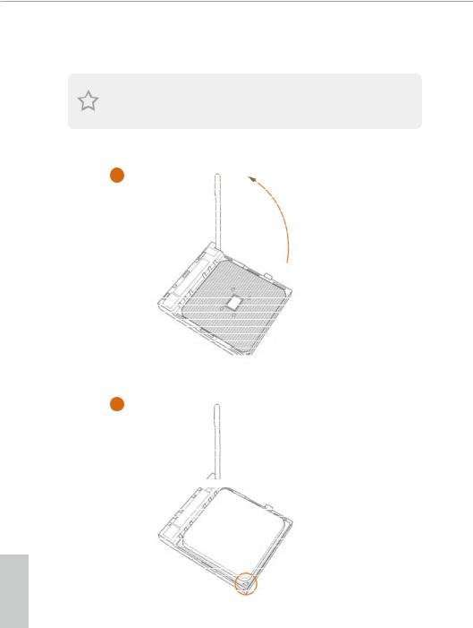
2.1 Installing the CPU
Unplug all power cables before installing the CPU.
1
2
English
12
Loading...