


Copyright Notice:
No part of this installation guide may be reproduced, transcribed, transmitted, or translated in any language, in any form or by any means, except duplication of documentation by the purchaser for backup purpose, without written consent of ASRock Inc.
Products and corporate names appearing in this guide may or may not be registered trademarks or copyrights of their respective companies, and are used only for identification or explanation and to the owners’ benefit, without intent to infringe.
Disclaimer:
Specifications and information contained in this guide are furnished for informational use only and subject to change without notice, and should not be constructed as a commitment by ASRock. ASRock assumes no responsibility for any errors or omissions that may appear in this guide.
With respect to the contents of this guide, ASRock does not provide warranty of any kind, either expressed or implied, including but not limited to the implied warranties or conditions of merchantability or fitness for a particular purpose. In no event shall ASRock, its directors, officers, employees, or agents be liable for any indirect, special, incidental, or consequential damages (including damages for loss of profits, loss of business, loss of data, interruption of business and the like), even if ASRock has been advised of the possibility of such damages arising from any defect or error in the guide or product.
This device complies with Part 15 of the FCC Rules. Operation is subject to the following two conditions:
(1)this device may not cause harmful interference, and
(2)this device must accept any interference received, including interference that may cause undesired operation.
CALIFORNIA, USA ONLY
The Lithium battery adopted on this motherboard contains Perchlorate, a toxic substance controlled in Perchlorate Best Management Practices (BMP) regulations passed by the California Legislature. When you discard the Lithium battery in California, USA, please follow the related regulations in advance.
“Perchlorate Material-special handling may apply, see www.dtsc.ca.gov/hazardouswaste/perchlorate”
ASRock Website: http://www.asrock.com
Published March 2013
Copyright©2013 ASRock INC. All rights reserved.
1
English
ASRock AD2550-ITX Motherboard
English
2
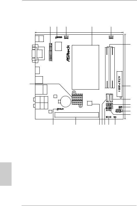
Motherboard Layout
|
|
|
1 |
2 |
3 |
4 |
|
5 |
|
|
|
|
|
|
|
17.0cm (6.7 in) |
|
|
|
|
|
|
|
|
|
COM1 |
USB 3.0 |
|
|
|
|
|
Keyboard PS2 |
|
|
|
|
|
|
|
|
|
|
USB 2.0 |
|
|
|
|
|
|
|
|
|
|
T: USB0 |
|
|
1 |
|
|
|
|
|
|
|
|
|
|
CPU_FAN1 |
|
CHA_FAN1 |
|
|
|||
B: USB1 |
|
|
|
|
|
|
||||
|
|
|
|
|
|
|
|
|
||
|
|
|
|
|
|
|
|
|
|
|
|
|
|
|
Super |
|
|
|
|
|
6 |
|
|
|
|
|
|
|
|
|
|
|
|
|
|
|
IO |
|
|
|
|
|
|
|
DVI |
|
|
|
|
|
|
|
|
|
|
CON1 |
|
LPT1 |
|
|
module) |
module) |
|
in) |
|
|
1 |
|
|
|
|
|||||
|
|
|
|
|
-pinFSB800 |
-pinFSB800 |
|
|||
HDMI1 |
|
|
|
|
|
|
DDR3 A1(64bit,204 |
DDR3 A2(64bit,204 |
|
17.0cm(6.7 |
USB 3.0 |
|
|
|
|
|
|
|
|
|
|
T: USB2 |
|
|
|
|
|
|
|
|
|
|
B: USB3 |
|
|
|
|
|
|
|
|
|
|
20 |
|
|
|
|
|
|
|
|
|
|
USB 2.0 |
|
|
|
RoHS |
|
|
|
|
7 |
|
Top: |
|
|
|
|
|
|
|
|
||
T: USB4 |
|
|
|
|
|
|
|
|
||
RJ-45 |
|
|
|
|
|
|
|
|||
B: USB5 |
|
|
|
|
|
|
|
|||
|
|
|
|
|
|
SATAII_1 |
|
SATAII_2 |
|
|
|
|
|
|
LAN |
|
|
|
|
|
|
SPDI Optical Bottom: F |
REAR Center: SPK |
CTR BAS S |
Top: |
PHY |
|
|
|
|
|
|
|
CMOS |
|
|
|
|
8 |
||||
Battery |
16Mb |
|
|
|
|
|||||
|
|
|
|
|
|
|
|
|||
MI Bottom: CI N |
FRON Center: T |
LINE Top: IN |
|
|
BIOS |
|
|
|
9 |
|
|
|
1 |
|
USB8_9 |
IR1 |
|||||
|
|
|
|
1 |
|
10 |
||||
|
|
|
|
|
AD2550-ITX |
1 |
|
USB6_7 PLED PWRBTN |
||
|
|
|
|
1 |
1 |
|
|
|
11 |
|
|
|
|
AUDIO |
HD_AUDIO1 |
|
CIR1 |
1 |
|
||
|
|
|
|
|
|
|
||||
|
|
|
CODEC |
|
|
|
|
|
|
|
|
|
|
|
|
|
|
|
HDLED |
RESET |
|
|
|
|
|
|
|
|
|
PANEL 1 |
|
12 |
|
|
|
|
|
PCI1 |
|
SPEAKER1 |
CLRCMOS1 |
|
|
|
|
|
|
|
|
1 |
|
1 |
|
|
|
|
|
19 |
18 |
17 1615 14 |
13 |
|
|
||
1 |
Print Port Header (LPT1, White) |
12 |
Consumer Infrared Module Header (CIR1) |
2 |
COM Port Header (COM1) |
13 |
Clear CMOS Jumper (CLRCMOS1) |
3 |
CPU Fan Connector (CPU_FAN1) |
14 |
Chassis Speaker Header |
4 |
CPU Heatsink |
|
(SPEAKER 1, White) |
5 |
Chassis Fan Connector (CHA_FAN1) |
15 |
USB 2.0 Header (USB6_7, Blue) |
6 |
2 x 204-pin DDR3 SO-DIMM Slots |
16 |
SATA2 Connector (SATAII_1, Blue) |
|
(DDR3_A1, DDR3_A2, Black) |
17 |
16Mb SPI Flash |
7 |
ATX Power Connector (ATXPWR1) |
18 |
PCI Slot (PCI1) |
8 |
SATA2 Connector (SATAII_2, Blue) |
19 |
Front Panel Audio Header |
9 |
USB 2.0 Header (USB8_9, Blue) |
|
(HD_AUDIO1, White) |
10 |
Infrared Module Header (IR1) |
20 |
Intel NM10 Express Chip |
11 |
System Panel Header (PANEL1, White) |
|
|
ASRock AD2550-ITX Motherboard
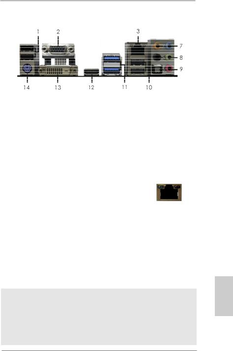
I/O Panel
1 |
USB 2.0 Ports |
** 8 |
Front Speaker (Lime) |
|
2 |
D-Sub Port |
9 |
Microphone (Pink) |
|
* 3 |
LAN RJ-45 Port |
10 |
USB 2.0 |
Ports |
4 |
Central / Bass (Orange) |
11 |
USB 3.0 |
Ports (ASMedia ASM1042) |
5 |
Rear Speaker (Black) |
12 |
HDMI Port |
|
6 |
Optical SPDIF Out Port |
13 |
DVI-D Port |
|
7 |
Line In (Light Blue) |
14 |
PS/2 Keyboard Port (Purple) |
|
*There are two LED next to the LAN port. Please refer to the table below for the LAN port LED indications.
LAN Port LED Indications
Activity/Link LED |
|
SPEED LED |
ACT/LINK |
SPEED |
|||||
|
LED |
LED |
|||||||
|
|
|
|
|
|
||||
Status |
Description |
|
Status |
|
Description |
|
|
|
|
Off |
No Link |
|
Off |
|
10Mbps connection |
|
|
|
|
|
|
|
|
||||||
Blinking |
Data Activity |
|
Orange |
|
100Mbps connection |
|
|
|
|
On |
Link |
|
Green |
|
1Gbps connection |
LAN Port |
|||
|
|
|
|
|
|
||||
**If you use 2-channel speaker, please connect the speaker’s plug into “Front Speaker Jack”. See the table below for connection details in accordance with the type of speaker you use.
TABLE for Audio Output Connection
Audio Output Channels |
Front Speaker |
Rear Speaker |
Central / Bass |
Line In or |
|
(No. 8) |
(No. 5) |
(No. 4) |
Side Speaker |
|
|
|
|
(No. 7) |
|
|
|
|
|
2 |
V |
-- |
-- |
-- |
4 |
V |
V |
-- |
-- |
6 |
V |
V |
V |
-- |
8 |
V |
V |
V |
V |
To enable Multi-Streaming function, you need to connect a front panel audio cable to the front panel audio header. After restarting your computer, you will find “Mixer” tool on your system.
Please select “Mixer ToolBox”  , click “Enable playback multi-streaming”, and click
“ok”. Choose “2CH”, “4CH”, “6CH”, or “8CH” and then you are allowed to select “Realtek HDA Primary output” to use Rear Speaker, Central/Bass, and Front Speaker, or select “Realtek HDA Audio 2nd output” to use front panel audio.
3
English
ASRock AD2550-ITX Motherboard

1. Introduction
Thank you for purchasing ASRock AD2550-ITX motherboard, a reliable motherboard produced under ASRock’s consistently stringent quality control. It delivers excellent performance with robust design conforming to ASRock’s commitment to quality and endurance.
This Quick Installation Guide contains introduction of the motherboard and step-by- step installation guide. More detailed information of the motherboard can be found in the user manual presented in the Support CD.
Because the motherboard specifications and the BIOS software might be updated, the content of this manual will be subject to change without notice. In case any modifications of this manual occur, the updated version will be available on ASRock website without further notice. You may find the latest VGA cards and CPU support lists on ASRock website as well. ASRock website http://www.asrock.com
If you require technical support related to this motherboard, please visit our website for specific information about the model you are using. www.asrock.com/support/index.asp
1.1 Package Contents
ASRock AD2550-ITX Motherboard
(Mini-ITX Form Factor: 6.7-in x 6.7-in, 17.0 cm x 17.0 cm) ASRock AD2550-ITX Quick Installation Guide
ASRock AD2550-ITX Support CD
2 x Serial ATA (SATA) Data Cables (Optional)
1 x I/O Panel Shield
English
4
ASRock AD2550-ITX Motherboard

1.2Specifications
Platform |
- Mini-ITX Form Factor: 6.7-in x 6.7-in, 17.0 cm x 17.0 cm |
|
- All Solid Capacitor design |
CPU |
- Intel® Dual-Core AtomTM Processor D2550 (1.86 GHz) |
|
- Supports Hyper-Threading Technology |
Chipset |
- Southbridge: Intel® NM10 Express |
Memory |
- 2 x DDR3 SO-DIMM slots |
|
- Supports DDR3 1066/800 non-ECC, un-buffered |
|
memory |
|
- Max. capacity of system memory: 4GB (see CAUTION 1) |
Expansion Slot |
- 1 x PCI slot |
Graphics |
- Intel® PowerVR SGX545 |
|
- DirectX 9.0, Pixel Shader 3.0 |
|
- Three VGA Output options: D-Sub, DVI-D and HDMI |
|
(see CAUTION 2) |
|
- Supports HDMI 1.3a Technology with max. resolution up to |
|
1920x1200 |
|
- Supports DVI with max. resolution up to 1920x1200 @ 60Hz |
|
- Supports D-Sub with max. resolution up to 1920x1200 @ |
|
60Hz |
|
- Supports HDCP function with DVI and HDMI ports |
|
- Supports Full HD 1080p Blu-ray (BD) / HD-DVD playback |
|
with DVI and HDMI ports |
|
|
Audio |
- 7.1 CH HD Audio with Content Protection |
|
(Realtek ALC892 Audio Codec) |
|
- Premium Blu-ray audio support |
LAN |
- PCIE x1 Gigabit LAN 10/100/1000 Mb/s |
|
- Realtek RTL8111E |
|
- Supports Wake-On-LAN |
|
- Supports LAN Cable Detection |
|
- Supports Energy Efficient Ethernet 802.3az |
|
- Supports PXE |
Rear Panel I/O |
I/O Panel |
|
- 1 x PS/2 Keyboard Port |
|
- 1 x D-Sub Port |
|
- 1 x DVI-D Port |
|
- 1 x HDMI Port |
|
- 1 x Optical SPDIF Out Port |
|
- 4 x USB 2.0 Ports |
|
- 2 x USB 3.0 Ports (ASMedia ASM1042) |
English
5
ASRock AD2550-ITX Motherboard

English
|
- 1 x RJ-45 LAN Port with LED (ACT/LINK LED and SPEED |
|
LED) |
|
- HD Audio Jack: Rear Speaker/Central/Bass/Line in/Front |
|
Speaker/Microphone |
Connector |
- 2 x SATA2 3.0 Gb/s connectors, support NCQ, AHCI and |
|
Hot Plug functions |
|
- 1 x IR header |
|
- 1 x CIR header |
|
- 1 x Print Port header |
|
- 1 x COM port header |
|
- 1 x CPU Fan connector (3-pin) |
|
- 1 x Chassis Fan connector (3-pin) |
|
- 1 x 24 pin ATX power connector |
|
- 1 x Front panel audio connector |
|
- 2 x USB 2.0 headers (support 4 USB 2.0 ports) |
BIOS Feature |
- 16Mb AMI UEFI Legal BIOS with GUI support |
|
- Supports “Plug and Play” |
|
- ACPI 1.1 Compliance Wake Up Events |
|
- Supports jumperfree |
|
- SMBIOS 2.3.1 Support |
Support CD |
- Drivers, Utilities, AntiVirus Software (Trial Version), |
|
CyberLink MediaEspresso 6.5 Trial, Google Chrome |
|
Browser and Toolbar |
Hardware |
- CPU Temperature Sensing |
Monitor |
- Chassis Temperature Sensing |
|
- CPU Fan Tachometer |
|
- Chassis Fan Tachometer |
|
- CPU/Chassis Quiet Fan |
|
- Voltage Monitoring: +12V, +5V, +3.3V, CPU Vcore |
OS |
- Microsoft® Windows® 7 32-bit compliant |
|
* Due to lack of Intel® 64-bit VGA driver support, this |
|
motherboard does not support 64-bit OS. |
Certifications |
- FCC, CE, WHQL |
|
- ErP/EuP Ready (ErP/EuP ready power supply is required) |
* For detailed product information, please visit our website: http://www.asrock.com
6
ASRock AD2550-ITX Motherboard

WARNING
Please realize that there is a certain risk involved with overclocking, including adjusting the setting in the BIOS, applying Untied Overclocking Technology, or using the third-party overclocking tools. Overclocking may affect your system stability, or even cause damage to the components and devices of your system.
It should be done at your own risk and expense. We are not responsible for possible damage caused by overclocking.
CAUTION!
1.Due to the chipset limitation, the actual memory size may be less than 4GB for the reservation for system usage under Windows® OS.
2.You can choose to use two of the three monitors only. D-Sub, DVI-D and HDMI monitors cannot be enabled at the same time. Besides, with the DVI-to-HDMI adapter, the DVI-D port can support the same features as HDMI port.
English
7
ASRock AD2550-ITX Motherboard

English
1.3 Unique Features
ASRock Instant Boot
ASRock Instant Boot allows you to turn on your PC in just a few seconds, provides a much more efficient way to save energy, time, money, and improves system running speed for your system. It leverages the S3 and S4 ACPI features which normally enable the Sleep/Standby and Hibernation modes in Windows® to shorten boot up time. By calling S3 and S4 at specific timing during the shutdown and startup process, Instant Boot allows you to enter your Windows® desktop in a few seconds.
ASRock Instant Flash
ASRock Instant Flash is a BIOS flash utility embedded in Flash
ROM. This convenient BIOS update tool allows you to update system BIOS without entering operating systems first like MS-
DOS or Windows®. With this utility, you can press the <F6> key during the POST or the <F2> key to enter into the BIOS setup menu to access ASRock Instant Flash. Just launch this tool and save the new BIOS file to your USB flash drive, floppy disk or hard drive, then you can update your BIOS only in a few clicks without preparing an additional floppy diskette or other complicated flash utility. Please be noted that the USB flash drive or hard drive must use FAT32/16/12 file system.
ASRock APP Charger
If you desire a faster, less restricted way of charging your Apple devices, such as iPhone/iPad/iPod Touch, ASRock has prepared a wonderful solution for you - ASRock APP Charger. Simply install the APP Charger driver, it makes your iPhone charge much quickly from your computer and up to 40% faster than before. ASRock APP Charger allows you to quickly charge many Apple devices simultaneously and even supports continuous charging when your PC enters into Standby mode (S1),
Suspend to RAM (S3), hibernation mode (S4) or power off (S5). With APP Charger driver installed, you can easily enjoy the marvelous charging experience.
8
ASRock AD2550-ITX Motherboard

ASRock XFast USB
ASRock XFast USB can boost USB storage device performance. The performance may depend on the properties of the device.
ASRock XFast LAN
ASRock XFast LAN provides a faster internet access, which includes the benefits listed below. LAN Application Prioritization: You can configure your application’s priority ideally and/or add new programs. Lower Latency in Game: After setting online game’s priority higher, it can lower the latency in games. Traffic
Shaping: You can watch Youtube HD videos and download simultaneously. Real-Time Analysis of Your Data: With the status window, you can easily recognize which data streams you are transferring currently.
ASRock XFast RAM
ASRock XFast RAM is a new function that is included into ASRock Extreme Tuning Utility (AXTU). It fully utilizes the memory space that cannot be used under Windows® OS 32-bit CPU. ASRock XFast RAM shortens the loading time of previously visited websites, making web surfing faster than ever. And it also boosts the speed of Adobe Photoshop 5 times faster. Another advantage of ASRock XFast RAM is that it reduces the frequency of accessing your SSDs or HDDs in order to extend their lifespan.
ASRock On/Off Play Technology
ASRock On/Off Play Technology allows users to enjoy the great audio experience from the portable audio devices, such like MP3 player or mobile phone to your PC, even when the PC is turned off (or in ACPI S5 mode)! This motherboard also provides a free 3.5mm audio cable (optional) that ensures users the most convenient computing environment.
English
9
ASRock AD2550-ITX Motherboard
2. Installation
This is a Mini-ITX form factor (6.7" x 6.7", 17.0 x 17.0 cm) motherboard. Before you install the motherboard, study the configuration of your chassis to ensure that the motherboard fits into it.
Make sure to unplug the power cord before installing or removing the motherboard. Failure to do so may cause physical injuries to you and damages to motherboard components.
2.1 Screw Holes
Place screws into the holes indicated by circles to secure the motherboard to the chassis.
Do not over-tighten the screws! Doing so may damage the motherboard.
2.2 Pre-installation Precautions
Take note of the following precautions before you install motherboard components or change any motherboard settings.
1.Unplug the power cord from the wall socket before touching any component.
2.To avoid damaging the motherboard components due to static electricity, NEVER place your motherboard directly on the carpet or the like. Also remember to use a grounded wrist strap or touch a safety grounded object before you handle components.
3.Hold components by the edges and do not touch the ICs.
4.Whenever you uninstall any component, place it on a grounded antistatic pad or in the bag that comes with the component.
Before you install or remove any component, ensure that the power is switched off or the power cord is detached from the power supply.
Failure to do so may cause severe damage to the motherboard, peripherals, and/or components.
English
10
ASRock AD2550-ITX Motherboard
2.3 Installation of Memory Modules (SO-DIMM)
AD2550-ITX motherboard provides two 204-pin DDR3 (Double Data Rate 3) SO-
DIMM slots.
1.It is not allowed to install a DDR or DDR2 memory module into DDR3 slot; otherwise, this motherboard and SO-DIMM may be damaged.
2.Please install the memory module from DDR3_A2 slot for the first priority.
Installing a SO-DIMM
Please make sure to disconnect power supply before adding or removing SO-DIMMs or the system components.
Step 1. Unlock a SO-DIMM slot by pressing the retaining clips outward. Step 2. Align a SO-DIMM on the slot such that the notch on the SO-DIMM
matches the break on the slot.
notch
break
notch
break
The SO-DIMM only fits in one correct orientation. It will cause permanent damage to the motherboard and the SO-DIMM if you force the SODIMM into the slot at incorrect orientation.
Step 3. Firmly insert the SO-DIMM into the slot until the retaining clips at both ends fully snap back in place and the SO-DIMM is properly seated.
English
11
ASRock AD2550-ITX Motherboard

2.4 Expansion Slot (PCI Slot)
There is 1 PCI slot on this motherboard.
PCI slot: The PCI slot is used to install expansion card that has the 32-bit PCI interface.
Installing an expansion card
Step 1. Before installing the expansion card, please make sure that the power supply is switched off or the power cord is unplugged. Please read the documentation of the expansion card and make necessary hardware settings for the card before you start the installation.
Step 2. Remove the system unit cover (if your motherboard is already installed in a chassis).
Step 3. Remove the bracket facing the slot that you intend to use. Keep the screws for later use.
Step 4. Align the card connector with the slot and press firmly until the card is completely seated on the slot.
Step 5. Fasten the card to the chassis with screws. Step 6. Replace the system cover.
English
12
ASRock AD2550-ITX Motherboard

2.5 Pin Header Easy Installation Guide
ASRock motherboard is equipped with pin headers with obvious colors which indicate you to recognize the crucial headers more easily. Please refer to below illustrations for the pin definition of onboard headers. If you want to have more information about the usage of these headers, please refer to “Jumpers Setup“ and “Onboard Headers and Connectors“ for details.
GND
PRESENCE#
MIC_RET
OUT_RET
1 |
OUT2_L J_SENSE
OUT2_R
MIC2_R MIC2_L
Front Panel Audio Header
USB_PWR
P-
P+GND
DUMMY
1 |
GND |
P+ |
P-
USB_PWR
USB 2.0 Header
PLED+
PLED-
PWRBTN# |
GND |
1 |
DUMMY
REST#
GND
HDLED-
|
HDLED+ |
1 |
System Panel Header |
SPEAKER |
|
DUMMY |
|
+5VDUMMY |
|
Chassis Speaker Header
English
13
ASRock AD2550-ITX Motherboard
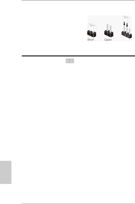
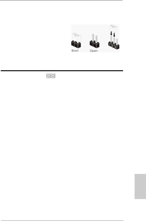
2.6 Jumpers Setup
The illustration shows how jumpers are setup. When the jumper cap is placed on pins, the jumper is “Short”. If no jumper cap is placed on pins, the jumper is “Open”. The illustration shows a 3-pin jumper whose pin1 and pin2 are “Short” when jumper cap is placed on these 2 pins.
Jumper |
Setting |
Description |
Clear CMOS
(CLRCMOS1, 2-pin jumper) (see p.2 No. 13)
2-pin jumper
Note: CLRCMOS1 allows you to clear the data in CMOS. The data in CMOS includes system setup information such as system password, date, time, and system setup parameters. To clear and reset the system parameters to default setup, please turn off the computer and unplug the power cord from the power supply. After waiting for 15 seconds, use a jumper cap to short 2 pins on CLRCMOS1 for 5 seconds.
English
14
ASRock AD2550-ITX Motherboard
2.7 Onboard Headers and Connectors
Onboard headers and connectors are NOT jumpers. Do NOT place jumper caps over these headers and connectors. Placing jumper caps over the headers and connectors will cause permanent damage of the motherboard!
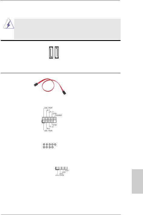
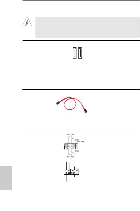
Serial ATA2 Connectors
(SATAII_1: see p.2, No. 16) (SATAII_2: see p.2, No. 8)
SATAII 1 |
SATAII 2 |
These two Serial ATA2 (SATA2) connectors support SATA data cables for internal storage devices. The current SATA2 interface allows up to 3.0 Gb/s data transfer rate.
Serial ATA (SATA) |
|
|
|
|
|
|
|
|
|
|
|
Either end of the SATA data |
Data Cable |
|
|
|
|
|
|
|
|
|
|
|
cable can be connected to the |
(Optional) |
|
|
|
|
|
|
|
|
|
|
|
SATA / SATA2 hard disk or the |
|
|
|
|
|
|
|
|
|
|
|
|
SATA2 connector on this |
|
|
|
|
|
|
|
|
|
|
|
|
motherboard. |
|
|
|
|
|
|
|
|
|
|
|
|
|
USB 2.0 Headers |
|
|
|
|
|
|
|
|
|
|
|
Besides the default USB 2.0 |
(9-pin USB6_7) |
|
|
|
|
|
|
|
|
|
|
|
ports on the I/O panel, there |
(see p.2 No. 15) |
|
|
|
|
|
|
|
|
|
|
|
are two USB 2.0 headers on |
|
|
|
|
|
|
|
|
|
|
|
|
this motherboard. Each |
|
|
|
|
|
|
|
|
|
|
|
|
USB 2.0 header can support |
|
|
|
|
|
|
|
|
|
|
|
|
two USB 2.0 ports. |
(9-pin USB8_9) |
|
|
USB_PWR |
|
|
|
|
|||||
|
|
|
|
|
P-9 |
|
|
|
|
|||
(see p.2 No. 9) |
|
|
|
|
|
|
P+9 |
|||||
|
|
|
|
|
|
|
|
GND |
||||
|
1 |
|
|
|
|
|
|
|
|
|
DUMMY |
|
|
|
|
|
|
|
|
|
|
|
|
|
|
|
|
|
|
|
|
|
|
|
|
|
|
|
|
|
|
|
|
|
|
|
|
GND |
|||
|
|
|
|
|
|
|
P+8 |
|||||
|
|
|
|
|
P-8 |
|
|
|
|
|||
|
|
|
USB_PWR |
|
|
|
|
|||||
|
|
|
|
|
|
|
|
|
|
|
|
|
Consumer Infrared Module Header |
|
|
|
This header can be used to |
||||||||
(4-pin CIR1) |
|
|
|
|
|
|
|
|
|
|
|
connect the remote controller |
(see p.2 No. 12) |
|
|
|
|
|
|
|
|
|
|
|
receiver. |
15
English
ASRock AD2550-ITX Motherboard
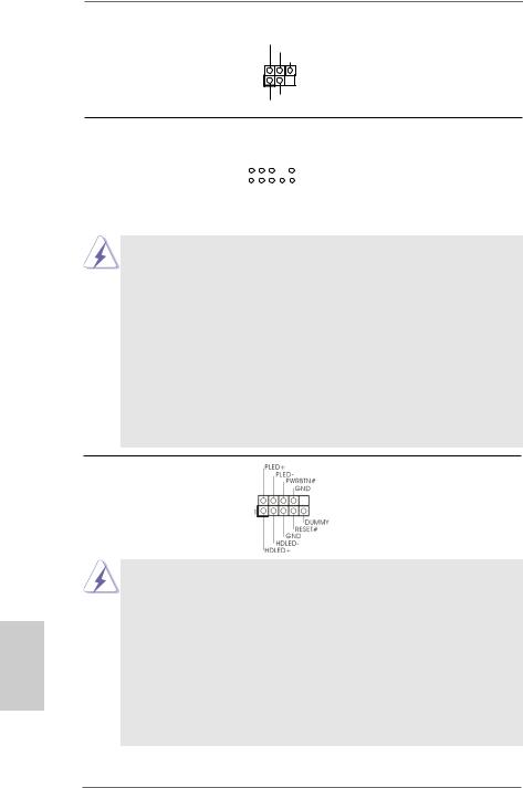
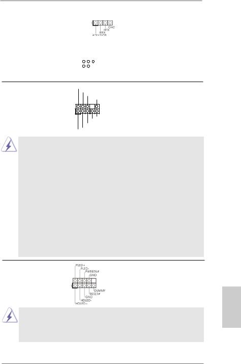
Infrared Module Header |
IRTX |
|
+5VSB |
(5-pin IR1) |
DUMMY |
(see p.2 No. 10) |
1 |
|
|
|
GND |
|
IRRX |
This header supports an optional wireless transmitting and receiving infrared module.
Front Panel Audio Header |
|
|
GND |
|||||||||
|
|
|
|
|
PRESENCE# |
|||||||
(9-pin HD_AUDIO1) |
|
|
|
|
|
|
MIC_RET |
|||||
|
|
|
|
|
|
|
|
|
|
OUT_RET |
||
|
|
|
|
|
|
|
|
|
|
|
||
(see p.2 No. 19) |
1 |
|
|
|
|
|
|
|
|
|
|
|
|
|
|
|
|
|
|
|
|
|
|
|
|
|
|
|
|
|
|
|
|
|
|
|
|
|
|
|
|
|
|
|
|
|
|
|
|
OUT2_L |
|
|
|
|
|
|
|
|
|
J_SENSE |
||||
|
|
|
|
|
|
|
OUT2_R |
|||||
|
|
|
|
|
MIC2_R |
|||||||
|
|
|
MIC2_L |
|||||||||
This is an interface for front panel audio cable that allows convenient connection and control of audio devices.
1.High Definition Audio supports Jack Sensing, but the panel wire on the chassis must support HDA to function correctly. Please follow the instruction in our manual and chassis manual to install your system.
2.If you use AC’97 audio panel, please install it to the front panel audio header as below:
A.Connect Mic_IN (MIC) to MIC2_L.
B.Connect Audio_R (RIN) to OUT2_R and Audio_L (LIN) to OUT2_L.
C.Connect Ground (GND) to Ground (GND).
D.MIC_RET and OUT_RET are for HD audio panel only. You don’t need to connect them for AC’97 audio panel.
E.To activate the front mic.
Go to the "FrontMic" Tab in the Realtek Control panel. Adjust “Recording Volume”.
System Panel Header |
This header accommodates |
(9-pin PANEL1) |
several system front panel |
(see p.2 No. 11) |
functions. |
English
16
Connect the power switch, reset switch and system status indicator on the chassis to this header according to the pin assignments below. Note the positive and negative pins before connecting the cables.
PWRBTN (Power Switch):
Connect to the power switch on the chassis front panel. You may configure the way to turn off your system using the power switch.
RESET (Reset Switch):
Connect to the reset switch on the chassis front panel. Press the reset switch to restart the computer if the computer freezes and fails to perform a normal restart.
ASRock AD2550-ITX Motherboard
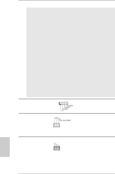
PLED (System Power LED):
Connect to the power status indicator on the chassis front panel. The LED is on when the system is operating. The LED keeps blinking when the system is in S1 sleep state. The LED is off when the system is in S3/S4 sleep state or powered off (S5).
HDLED (Hard Drive Activity LED):
Connect to the hard drive activity LED on the chassis front panel. The LED is on when the hard drive is reading or writing data.
The front panel design may differ by chassis. A front panel module mainly consists of power switch, reset switch, power LED, hard drive activity LED, speaker and etc. When connecting your chassis front panel module to this header, make sure the wire assignments and the pin assign-ments are matched correctly.
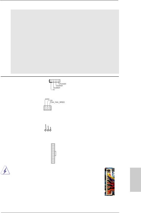
Chassis Speaker Header |
|
|
|
|
Please connect the chassis |
|
||||
(4-pin SPEAKER 1) |
|
|
|
|
speaker to this header. |
|
||||
(see p.2 No. 14) |
|
|
|
|
|
|
|
|
|
|
|
|
|
|
|
|
|
|
|
|
|
Chassis Fan Connector |
|
|
|
|
Please connect the fan cable |
|
||||
(3-pin CHA_FAN1) |
|
|
|
|
to the fan connector and |
|
||||
(see p.2 No. 5) |
|
|
|
|
match the black wire to the |
|
||||
|
|
|
|
|
|
ground pin. |
|
|
|
|
|
|
|
|
|
|
|
|
|
|
|
CPU Fan Connector |
GND |
|
|
Please connect the CPU fan |
|
|||||
(3-pin CPU_FAN1) |
CPU_FAN_SPEED |
cable to the connector and |
|
|||||||
|
|
|
+12V |
|
|
|
|
|
||
(see p.2 No. 3) |
|
|
|
|
match the black wire to the |
|
||||
|
|
|
|
|
||||||
|
|
|
|
|
|
ground pin. |
|
|
|
|
|
|
|
|
|
|
|
|
|
|
|
|
|
|
|
|
|
|||||
ATX Power Connector |
12 |
24 |
Please connect an ATX power |
|||||||
(24-pin ATXPWR1) |
|
|
|
|
supply to this connector. |
|
||||
(see p.2 No. 7) |
|
|
|
|
|
|
|
|
|
|
|
|
1 |
13 |
|
|
|
|
|
||
|
|
|
|
|
|
|
|
|||
|
Though this motherboard provides 24-pin ATX power connector, |
12 |
|
|
24 |
|||||
|
|
|
||||||||
|
it can still work if you adopt a traditional 20-pin ATX power supply. |
|
|
|
|
|||||
|
To use the 20-pin ATX power supply, please plug your |
|
|
|
|
|||||
|
power supply along with Pin 1 and Pin 13. |
|
|
|
|
|
||||
|
|
|
|
|
20-Pin ATX Power Supply Installation |
1 |
|
|
13 |
|
|
|
|
|
|
|
|
|
|
|
|
17
English
ASRock AD2550-ITX Motherboard
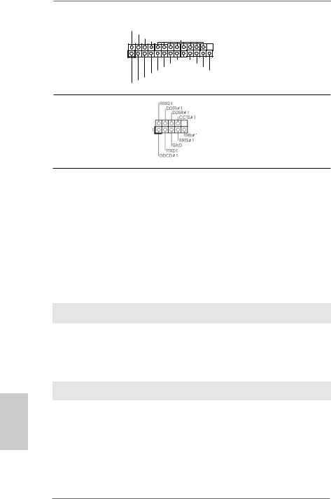
Print Port Header |
AFD# |
|
(25-pin LPT1) |
ERROR# |
GND |
PINIT# |
||
|
SLIN# |
|
(see p.2 No. 1) |
|
|
|
1 |
|
|
|
SPD7 |
|
SPD6 ACK# |
|
|
SPD5 |
BUSY |
|
SPD4 |
PE |
|
SPD3 |
SLCT |
|
SPD2 |
|
|
SPD1 |
|
|
SPD0 |
|
|
STB# |
|
This is an interface for print port cable that allows convenient connection of printer devices.
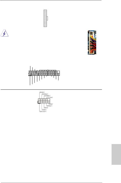
Serial port Header |
This COM1 header supports a |
(9-pin COM1) |
serial port module. |
(see p.2 No. 2) |
|
English
2.8Driver Installation Guide
To install the drivers to your system, please insert the support CD to your optical drive first. Then, the drivers compatible to your system can be auto-detected and listed on the support CD driver page. Please follow the order from up to bottom side to install those required drivers. Therefore, the drivers you install can work properly.
2.9 Installing Windows® 7 on SATA / SATAII HDDs
If you want to install Windows® 7 OS on your SATA / SATAII HDDs, please follow below steps.
Using SATA / SATAII HDDs with NCQ function
STEP 1: Set up UEFI.
A.Enter UEFI SETUP UTILITY  Advanced screen
  Storage Configuration.
B.Set the option “SATA Mode” to [AHCI].
STEP 2: Install Windows® 7 OS on your system.
Using SATA / SATAII HDDs without NCQ function
STEP 1: Set up UEFI.
A.Enter UEFI SETUP UTILITY  Advanced screen
  Storage Configuration.
B.Set the option “SATA Mode” to [IDE].
STEP 2: Install Windows® 7 OS on your system.
18
ASRock AD2550-ITX Motherboard

3. BIOS Information
The Flash Memory on the motherboard stores BIOS Setup Utility. When you start up the computer, please press <F2> or <Del> during the Power-On-Self-Test (POST) to enter BIOS Setup utility; otherwise, POST continues with its test routines. If you wish to enter BIOS Setup after POST, please restart the system by pressing <Ctl> + <Alt> + <Delete>, or pressing the reset button on the system chassis. The BIOS Setup program is designed to be user-friendly. It is a menu-driven program, which allows you to scroll through its various sub-menus and to select among the predetermined choices. For the detailed information about BIOS Setup, please refer to the
User Manual (PDF file) contained in the Support CD.
4. Software Support CD information
This motherboard supports various Microsoft® Windows® operating systems: 7 32bit. The Support CD that came with the motherboard contains necessary drivers and useful utilities that will enhance motherboard features. To begin using the Support CD, insert the CD into your CD-ROM drive. It will display the Main Menu automatically if “AUTORUN” is enabled in your computer. If the Main Menu does not appear automatically, locate and double-click on the file “ASSETUP.EXE” from the BIN folder in the Support CD to display the menus.
English
19
ASRock AD2550-ITX Motherboard

1. Einführung
Wir danken Ihnen für den Kauf des ASRock AD2550-ITX Motherboard, ein zuverlässiges Produkt, welches unter den ständigen, strengen Qualitätskontrollen von ASRock gefertigt wurde. Es bietet Ihnen exzellente Leistung und robustes Design, gemäß der Verpflichtung von ASRock zu Qualität und Halbarkeit. Diese Schnellinstallationsanleitung führt in das Motherboard und die schrittweise Installation ein. Details über das Motherboard finden Sie in der Bedienungsanleitung auf der
Support-CD.
Da sich Motherboard-Spezifikationen und BIOS-Software verändern können, kann der Inhalt dieses Handbuches ebenfalls jederzeit geändert werden. Für den Fall, dass sich Änderungen an diesem Handbuch ergeben, wird eine neue Version auf der ASRock-Website, ohne weitere
Ankündigung, verfügbar sein. Die neuesten Grafikkarten und unterstützten
CPUs sind auch auf der ASRock-Website aufgelistet. ASRock-Website: http://www.asrock.com
Wenn Sie technische Unterstützung zu Ihrem Motherboard oder spezifische
Informationen zu Ihrem Modell benötigen, besuchen Sie bitte unsere Webseite:
www.asrock.com/support/index.asp
1.1 Kartoninhalt
ASRock AD2550-ITX Motherboard
(Mini-ITX-Formfaktor: 17.0 cm x 17.0 cm; 6.7 Zoll x 6.7 Zoll)
ASRock AD2550-ITX Schnellinstallationsanleitung
ASRock AD2550-ITX Support-CD
Zwei Serial ATA (SATA) -Datenkabel (optional)
Ein I/O Shield
Deutsch
20
ASRock AD2550-ITX Motherboard
1.2Spezifikationen
Plattform |
- Mini-ITX-Formfaktor: 17.0 cm x 17.0 cm; 6.7 Zoll x 6.7 Zoll |
|
- Alle Feste Kondensatordesign |
CPU |
- Intel® Dual-Core AtomTM-Prozessor D2550 (1.86 GHz) |
|
- Unterstützt Hyper-Threading-Technologie |
Chipsatz |
- Southbridge: Intel® NM10 Express |
Speicher |
- 2 x SO-DIMM für DDR3 |
|
- Unterstützt DDR3 1066/800 non-ECC, ungepufferter |
|
Speicher |
|
- Max. Kapazität des Systemspeichers: 4GB |
Erweiterungs- |
- 1 x PCI -Steckplätze |
steckplätze |
|
Onboard-VGA |
- Intel® PowerVR SGX545 |
|
- DirectX 9.0, Pixel Shader 3.0 |
|
- Drei VGA-Ausgangsoptionen: D-Sub, DVI-D sowie HDMI |
|
- Unterstützt HDMI 1.3a mit einer maximalen Auflösung von |
|
1920 x 1200 |
|
- Unterstützt DVI-D mit einer maximalen Auflösung von |
|
1920 x 1200 bei 60 Hz |
|
- Unterstützt D-Sub mit einer maximalen Auflösung von |
|
1920 x 1200 bei 60 Hz |
|
- Unterstützt HDCP-Funktion mit DVI-D- und HDMI-Ports |
|
- Unterstutzt 1080p Blu-ray (BD) / HD-DVD-Wiedergabe mit |
|
DVI-D- und HDMI-Ports |
Audio |
- 7.1 CH HD Audio mit dem Inhalt Schutz |
|
(Realtek ALC892 Audio Codec) |
|
- Premium Blu-ray-Audio-Unterstützung |
LAN |
- PCIE x1 Gigabit LAN 10/100/1000 Mb/s |
|
- Realtek RTL8111E |
|
- Unterstützt Wake-On-LAN |
|
- Unterstützt LAN-Kabelerkennung |
|
- Unterstützt energieeffizientes Ethernet 802.3az |
|
- Unterstützt PXE |
E/A-Anschlüsse |
I/O Panel |
an der |
- 1 x PS/2-Tastaturanschluss |
Rückseite |
- 1 x D-Sub port |
|
- 1 x DVI-D port |
|
- 1 x HDMI port |
|
- 1 x optischer SPDIF-Ausgang |
|
- 4 x Standard-USB 2.0-Anschlüsse |
Deutsch
21
ASRock AD2550-ITX Motherboard

Deutsch
22
|
|
|
- 2 x Standard-USB 3.0-Anschlüsse (ASMedia ASM1042) |
|
- 1 x RJ-45 LAN Port mit LED (ACT/LINK LED und SPEED |
|
LED) |
|
- HD Audiobuchse: Lautsprecher hinten / Mitte/Bass / |
|
Audioeingang / Lautsprecher vorne / Mikrofon |
Anschlüsse |
- 2 x SATA2 3,0 GB/s-Anschlüsse, unterstützen NCQ-, AHCI- |
|
und „Hot Plug“ (Hot-Plugging)- Funktionen |
|
- 1 x Infrarot-Modul-Header |
|
- 1 x Consumer Infrared-Modul-Header |
|
- 1 x Druckerport-Anschlussleiste |
|
- 1 x COM-Anschluss-Header |
|
- 1 x CPUlüfter-Anschluss (3-pin) |
|
- 1 x Gehäuselüfter-Anschluss (3-pin) |
|
- 1 x 24-pin ATX-Netz-Header |
|
- 1 x Anschluss für Audio auf der Gehäusevorderseite |
|
- 2 x USB 2.0-Anschlüsse (Unterstützung 4 zusätzlicher |
|
USB 2.0-Anschlüsse) |
BIOS |
- 16Mb AMIs Legal BIOS UEFI mit GUI-Unterstützung |
|
- Unterstützung für “Plug and Play” |
|
- ACPI 1.1-Weckfunktionen |
|
- JumperFree-Übertaktungstechnologie |
|
- SMBIOS 2.3.1 |
CD d’assistance |
- Pilotes, utilitaires, logiciel anti-virus (version d’évaluation), |
|
CyberLink MediaEspresso 6.5 Trial, Google Chrome |
|
Browser und Toolbar |
Hardware Monitor |
- Überwachung der CPU-Temperatur |
|
- Motherboardtemperaturerkennung |
|
- Drehzahlmessung für CPU-Lüfter |
|
- Drehzahlmessung für Gehäuselüfter |
|
- CPU/Gehäuse-Lüftergeräuschdämpfung |
|
- Spannungsüberwachung: +12V, +5V, +3.3V, Vcore |
Betriebssysteme |
- Unterstützt Microsoft® Windows® 7 32-Bit |
Zertifizierungen |
- FCC, CE, WHQL |
-Gemäß Ökodesign-Richtlinie (ErP/EuP) (Stromversorgung gemäß Ökodesign-Richtlinie (ErP/EuP) erforderlich)
*Für die ausführliche Produktinformation, besuchen Sie bitte unsere Website: http://www.asrock.com
ASRock AD2550-ITX Motherboard
1.3 Einstellung der Jumper
Die Abbildung verdeutlicht, wie Jumper gesetzt werden. Werden Pins durch Jumperkappen verdeckt, ist der Jumper “Gebrückt”. Werden keine Pins durch Jumperkappen verdeckt, ist der Jumper “Offen”. Die Abbildung zeigt einen 3-Pin Jumper dessen Pin1 und Pin2 “Gebrückt” sind, bzw. es befindet sich eine
Jumper-Kappe auf diesen beiden Pins.
Jumper |
Einstellun |
Beschreibung |
CMOS löschen
(CLRCMOS1, 2-Pin jumper) (siehe S.2 - No. 13)
2-pin jumper
Hinweis: Mit CLRCMOS1 können Sie die Daten im CMOS löschen. Die CMOS Daten beinhalten die Systeminformationen wie Systemkennwort, Datum, Zeit und System-Setupeinstellungen. Um die Einstellungen zu löschen und Default-Werte wiederherzustellen, schalten Sie den Computer aus, ziehen Sie den Netzstecker und überbrücken Sie 2-pin von CLRCMOS1 mithilfe des Jumpers für 5 Sekunden.
Deutsch
23
ASRock AD2550-ITX Motherboard
Deutsch
1.4 Integrierte Header und Anschlüsse
Integrierte Header und Anschlüsse sind KEINE Jumper. Setzen Sie KEINE Jumperkappen auf diese Header und Anschlüsse. Wenn Sie Jumperkappen auf Header und Anschlüsse setzen, wird das Motherboard unreparierbar beschädigt!
Seriell-ATAII-Anschlüsse
(SATAII_1: siehe S.2 |
- No. 16) |
SATAII1 |
SATAII2 |
|
(SATAII_2: siehe S.2 |
- No. 8) |
|||
|
|
Serial ATA- (SATA-) Datenkabel
(Option)
Diese zwei Serial ATAII- (SATAII-) Verbínder unterstützten SATA-Datenkabel für interne Massenspeichergeräte. Die aktuelle SATAII-Schnittstelle ermöglicht eine Datenübertragungsrate bis
3,0 Gb/s.
SJedes Ende des SATA Datenkabels kann an die SATA / SATAII Festplatte
oder das SATAII Verbindungsstück auf dieser Hauptplatine angeschlossen werden.
USB 2.0-Header
(9-pol. USB6_7)
(siehe S.2 - No. 15)
(9-pol. USB8_9) |
USB_PWR |
|
P-9 |
||
|
||
(siehe S.2 - No. 9) |
P+9 |
|
GND |
||
|
DUMMY |
|
|
1 |
|
|
GND |
|
|
P+8 |
|
|
P-8 |
|
|
USB_PWR |
Zusätzlich zu den
üblichen USB 2.0-Ports an den
I/O-Anschlüssen befinden sich zwei USB 2.0- Anschlussleisten am Motherboard. Pro USB 2.0- Anschlussleiste werden zwei USB 2.0-Ports unterstützt.
24
ASRock AD2550-ITX Motherboard
Consumer Infrared-Modul-Header |
Dieser Header kann zum |
|||||||||
(4-pin CIR1) |
|
|
|
|
|
|
|
|
|
Anschließen Remote- |
(siehe S.2 - No. 12) |
|
|
|
|
|
|
|
|
|
Empfänger. |
|
|
|
|
|
|
|
|
|
|
|
Infrarot-Modul-Header |
|
IRTX |
Dieser Header unterstützt ein |
|||||||
|
|
|
+5VSB |
optionales, drahtloses Sende- |
||||||
(5-pin IR1) |
|
|
|
|
DUMMY |
|||||
(siehe S.2 - No. 10) |
1 |
|
|
|
|
|
|
|
|
und Empfangs-Infrarotmodul. |
|
|
|
|
|
|
|
|
|||
|
|
|
|
|
|
|
|
|||
|
|
|
|
|
|
|
|
|
||
|
|
|
|
GND |
|
|||||
|
|
IRRX |
|
|||||||
Anschluss für Audio auf |
GND |
|
der Gehäusevorderseite |
PRESENCE# |
|
MIC_RET |
||
|
||
|
OUT_RET |
(9-Pin HD_AUDIO1)
(siehe S.2 - No. 19) |
1 |
OUT2_L
J_SENSE
OUT2_R
MIC2_R
MIC2_L
Dieses Interface zu einem Audio-Panel auf der Vorder seite Ihres Gehäuses, ermöglicht Ihnen eine bequeme Anschlussmöglichkeit und Kontrolle über Audio-Geräte.
1.High Definition Audio unterstützt Jack Sensing (automatische Erkennung falsch angeschlossener Geräte), wobei jedoch die Bildschirmverdrahtung am Gehäuse HDA unterstützen muss, um richtig zu funktionieren.
Beachten Sie bei der Installation im System die Anweisungen in unserem Handbuch und im Gehäusehandbuch.
2.Wenn Sie die AC’97-Audioleiste verwenden, installieren Sie diese wie nachstehend beschrieben an der Front-Audioanschlussleiste:
A.Schließen Sie Mic_IN (MIC) an MIC2_L an.
B.Schließen Sie Audio_R (RIN) an OUT2_R und Audio_L (LIN) an OUT2_L an.
C.Schließen Sie Ground (GND) an Ground (GND) an.
D.MIC_RET und OUT_RET sind nur für den HD-Audioanschluss gedacht. Diese Anschlüsse müssen nicht an die AC’97-Audioleiste angeschlossen werden.
E.So aktivieren Sie das Mikrofon an der Vorderseite.
Wählen Sie im Realtek-Bedienfeld die „FrontMic“ (Vorderes Mikrofon)- Registerkarte. Passen Sie die „Recording Volume“ (Aufnahmelautstärke) an.
System Panel-Header |
Dieser Header unterstützt |
(9-pin PANEL1) |
mehrere Funktion der |
(siehe S.2 - No. 11) |
Systemvorderseite. |
Schließen Sie die Ein-/Austaste, die Reset-Taste und die Systemstatusanzeige am Gehäuse an diesen Header an; befolgen Sie dabei die nachstehenden Hinweise zur Pinbelegung. Beachten Sie die positiven und negativen Pins, bevor Sie die Kabel anschließen.
25
Deutsch
ASRock AD2550-ITX Motherboard
Deutsch
PWRBTN (Ein-/Ausschalter):
Zum Anschließen des Ein-/Ausschalters an der Frontblende des Gehäu ses. Sie können konfigurieren, wie das System mit Hilfe des
Ein-/Ausschalters ausgeschaltet werden können soll.
RESET (Reset-Taste):
Zum Anschließen der Reset-Taste an der Frontblende des Gehäuses. Mit der Reset-Taste können Sie den Computer im Falle eines Absturzes neu starten.
PLED (Systembetriebs-LED):
Zum Anschließen der Betriebsstatusanzeige an der Frontblende des Gehäuses. Die LED leuchtet, wenn das System in Betrieb ist. Die
LED blinkt, wenn sich das System im Ruhezustand S1 befindet. Die LED schaltet sich aus, wenn sich das System in den Modi S3/S4 befindet oder ausgeschaltet ist (S5).
HDLED (Festplattenaktivitäts-LED):
Zum Anschließen der Festplattenaktivitäts-LED an der Frontblende des Gehäuses. Die LED leuchtet, wenn die Festplatte Daten liest oder schreibt.
Das Design der Frontblende kann je nach Gehäuse variiere. Ein Frontblendenmodul besteht hauptsächlich aus einer Ein-/Austaste, einer Reset-Taste, einer Betriebs-LED, einer Festplattenaktivitäts-LED, Lautsprechern, etc. Stellen Sie beim Anschließen des Frontblendenmoduls Ihres Gehäuses an diesem Header sicher, dass die Kabelund Pinbelegung korrekt übereinstimmen.
Gehäuselautsprecher-Header |
Schließen Sie den |
(4-pin SPEAKER1) |
Gehäuselautsprecher an |
(siehe S.2 - No. 14) |
diesen Header an. |
Gehäuse-Lüfteranschlüsse
(3-pin CHA_FAN1)
(siehe S.2 - No. 5)
Verbinden Sie die Lüfterkabel mit den Lüfteranschlüssen, wobei der schwarze Draht an den Schutzleiterstift angeschlossen wird.
CPU-Lüfteranschluss
(3-pin CPU_FAN1) |
GND |
+12V |
|
|
CPU_FAN_SPEED |
(siehe S.2 - No. 3)
Verbinden Sie das CPU - Lüfterkabel mit diesem Anschluss und passen Sie den schwarzen Draht dem Erdungsstift an.
26
ASRock AD2550-ITX Motherboard
ATX-Netz-Header |
12 24 |
(24-pin ATXPWR1)
(siehe S.2 - No. 7)
1 13
Verbinden Sie die ATX-
Stromversorgung mit diesem
Header.
|
Obwohl dieses Motherboard einen 24-pol. ATX- |
12 |
|
24 |
|
|
|||
|
Stromanschluss bietet, kann es auch mit einem |
|
|
|
|
modifizierten traditionellen 20-pol. ATX-Netzteil |
|
|
|
|
verwendet werden. Um ein 20-pol. ATX-Netzteil zu |
|
|
|
|
verwenden, stecken Sie den Stecker mit Pin 1 und |
|
|
|
|
Pin 13 ein. |
|
|
|
|
Installation eines 20-pol. ATX-Netzteils |
1 |
13 |
|
|
|
|
|
|
|
|
|
|
|
Druckerport-Anschlussleiste
(25-pol. LPT1) |
ERROR# |
|
|
|
AFD# |
|
|
(siehe S.2 - No. 1) |
PINIT# |
GND |
|
SLIN# |
|
||
|
1 |
|
|
|
|
SPD7 |
|
|
|
SPD6 |
ACK# |
|
|
SPD5 |
BUSY |
|
|
SPD4 |
PE |
|
SPD3 |
SLCT |
|
|
SPD2 |
|
|
|
SPD1 |
|
|
|
SPD0 |
|
|
|
STB# |
|
|
Dies ist eine Schnittstelle zum Anschluss eines DruckerportKabels, mit dem Sie passende Drucker auf einfache Weise anschließen können.
COM-Anschluss-Header |
Dieser COM-Anschluss- |
(9-pin COM1) |
Header wird verwendet, um |
(siehe S.2 - No. 2) |
ein COM-Anschlussmodul zu |
|
unterstützen. |
Deutsch
27
ASRock AD2550-ITX Motherboard

2. BIOS-Information
Das Flash Memory dieses Motherboards speichert das Setup-Utility. Drücken Sie <F2> oder <Del> während des POST (Power-On-Self-Test) um ins Setup zu gelangen, ansonsten werden die Testroutinen weiter abgearbeitet. Wenn Sie ins Setup gelangen wollen, nachdem der POST durchgeführt wurde, müssen Sie das System über die Tastenkombination <Ctrl> + <Alt> + <Delete> oder den Reset-Knopf auf der Gehäusevorderseite, neu starten. Natürlich können Sie einen Neustart auch durchführen, indem Sie das System kurz abund danach wieder anschalten.
Das Setup-Programm ist für eine bequeme Bedienung entwickelt worden. Es ist ein menügesteuertes Programm, in dem Sie durch unterschiedliche Untermenüs scrollen und die vorab festgelegten Optionen auswählen können. Für detaillierte Informationen zum BIOS-Setup, siehe bitte das Benutzerhandbuch (PDF Datei) auf der Support CD.
3. Software Support CD information
Dieses Motherboard unterstützt eine Reiche von Microsoft® Windows® Betriebssystemen: 7 32-Bit. Die Ihrem Motherboard beigefügte Support-CD enthält hilfreiche Software, Treiber und Hilfsprogramme, mit denen Sie die Funktionen Ihres Motherboards verbessern können Legen Sie die Support-CD zunächst in Ihr CD-ROM- Laufwerk ein. Der Willkommensbildschirm mit den Installationsmenüs der CD wird automatisch aufgerufen, wenn Sie die “Autorun”-Funktion Ihres Systems aktiviert haben.
Erscheint der Wilkommensbildschirm nicht, so “doppelklicken” Sie bitte auf das File ASSETUP.EXE im BIN-Verzeichnis der Support-CD, um die Menüs aufzurufen. Das Setup-Programm soll es Ihnen so leicht wie möglich machen. Es ist menügesteuert, d.h. Sie können in den verschiedenen Untermenüs Ihre Auswahl treffen und die Programme werden dann automatisch installiert.
Deutsch
28
ASRock AD2550-ITX Motherboard

1. Introduction
Merci pour votre achat d’une carte mère ASRock AD2550-ITX, une carte mère très fiable produite selon les critères de qualité rigoureux de ASRock. Elle offre des performances excellentes et une conception robuste conformément à l’engagement d’ASRock sur la qualité et la fiabilité au long terme.
Ce Guide d’installation rapide présente la carte mère et constitue un guide d’installation pas à pas. Des informations plus détaillées concernant la carte mère pourront être trouvées dans le manuel l’utilisateur qui se trouve sur le CD d’assistance.
Les spécifications de la carte mère et le BIOS ayant pu être mis à jour, le contenu de ce manuel est sujet à des changements sans notification. Au cas où n’importe qu’elle modification intervenait sur ce manuel, la version mise à jour serait disponible sur le site web ASRock sans nouvel avis. Vous trouverez les listes de prise en charge des cartes VGA et CPU également sur le site Web ASRock. Site web ASRock, http://www.asrock.com
Si vous avez besoin de support technique en relation avec cette carte mère, veuillez consulter notre site Web pour de plus amples informations particulières au modèle que vous utilisez. www.asrock.com/support/index.asp
1.1 Contenu du paquet
Carte mère ASRock AD2550-ITX
(Facteur de forme Mini-ITX: 6.7 pouces x 6.7 pouces, 17.0 cm x 17.0 cm) Guide d’installation rapide ASRock AD2550-ITX
CD de soutien ASRock AD2550-ITX
Deux câbles de données de série ATA (SATA) (en option) Un I/O Panel Shield
Français
29
ASRock AD2550-ITX Motherboard

Français
1.2 Spécifications
Format |
- Facteur de forme Mini-ITX: |
|
6.7 pouces x 6.7 pouces, 17.0 cm x 17.0 cm |
|
- Accessoires de Carte mère |
CPU |
- Processeur Intel® AtomTM double-cœur D2550 (1.86 GHz) |
|
- Prise en charge de la technologie Hyper-Threading |
Chipsets |
- Southbridge: Intel® NM10 Express |
Mémoire |
- 2 x slots SO-DIMM DDR3 |
|
- Supporte DDR3 1066/800 non-ECC, sans amortissement |
|
mémoire |
|
- Capacité maxi de mémoire système: 4GB |
Slot d’extension |
- 1 x slot PCI |
VGA sur carte |
- Intel® PowerVR SGX545 |
|
- DirectX 9.0, Pixel Shader 3.0 |
|
- Trois options de sortie VGA: D-Sub, DVI-D et HDMI |
|
- Prend en charge le HDMI 1.3a avec une résolution |
|
maximale jusqu’à 1920x1200 |
|
- Prend en charge le DVI-D avec une résolution maximale |
|
jusqu’à 1920x1200 @ 60Hz |
|
- Prend en charge le D-Sub avec une résolution maximale |
|
jusqu’à 1920x1200 @ 60Hz |
|
- Prise en charge de la fonction HDCP avec ports DVI-D et |
|
HDMI |
|
- Supporter 1080p Blu-ray(BD)/ lecteur de HD-DVD avec |
|
ports DVI-D et HDMI |
Audio |
- 7,1 CH HD Audio avec protection de contenu |
|
(Realtek ALC892 Audio Codec) |
|
- Prise en charge de l’audio Premium Blu-ray |
LAN |
- PCIE x1 Gigabit LAN 10/100/1000 Mb/s |
|
- Realtek RTL8111E |
|
- Support du Wake-On-LAN |
|
- Prise en charge de la détection de câble LAN |
|
- Prend en charge la norme Energy Efficient Ethernet |
|
(Ethernet à efficacité énergétique) 802.3az |
|
- Supporte PXE |
Panneau arrière |
I/O Panel |
|
- 1 x port clavier PS/2 |
|
- 1 x port D-Sub |
|
- 1 x port DVI-D |
|
- 1 x port HDMI |
30
ASRock AD2550-ITX Motherboard
 Loading...