


A320M Pro4 R2.0
Table of contents
 Loading...

Version 1.0
Published November 2018
Copyright©2018 ASRock INC. All rights reserved.
Copyright Notice:
No part of this documentation may be reproduced, transcribed, transmitted, or
translated in any language, in any form or by any means, except duplication of
documentation by the purchaser for backup purpose, without written consent of
ASRock Inc.
Products and corporate names appearing in this documentation may or may not
be registered trademarks or copyrights of their respective companies, and are used
only for identication or explanation and to the owners’ benet, without intent to
infringe.
Disclaimer:
Specications and information contained in this documentation are furnished for
informational use only and subject to change without notice, and should not be
constructed as a commitment by ASRock. ASRock assumes no responsibility for
any errors or omissions that may appear in this documentation.
With respect to the contents of this documentation, ASRock does not provide
warranty of any kind, either expressed or implied, including but not limited to
the implied warranties or conditions of merchantability or tness for a particular
purpose.
In no event shall ASRock, its directors, ocers, employees, or agents be liable for
any indirect, special, incidental, or consequential damages (including damages for
loss of prots, loss of business, loss of data, interruption of business and the like),
even if ASRock has been advised of the possibility of such damages arising from any
defect or error in the documentation or product.
is device complies with Part 15 of the FCC Rules. Operation is subject to the following
two conditions:
(1) this device may not cause harmful interference, and
(2) this device must accept any interference received, including interference that
may cause undesired operation.
CALIFORNIA, USA ONLY
e Lithium battery adopted on this motherboard contains Perchlorate, a toxic substance
controlled in Perchlorate Best Management Practices (BMP) regulations passed by the
California Legislature. When you discard the Lithium battery in California, USA, please
follow the related regulations in advance.
“Perchlorate Material-special handling may apply, see ww w.dtsc.ca.gov/hazardouswaste/
perchlorate”
ASRock Website: http://www.asrock.com

AUSTRALIA ONLY
Our goods come with guarantees that cannot be excluded under the Australian Consumer
Law. You are entitled to a replacement or refund for a major failure and compensation for
any other reasonably foreseeable loss or damage caused by our goods. You are also entitled
to have the goods repaired or replaced if the goods fail to be of acceptable quality and the
failure does not amount to a major failure. If you require assistance please call ASRock Tel
: +886-2-28965588 ext.123 (Standard International call charges apply)
e terms HDMI® and HDMI High-Denition Multimedia Interface, and the HDMI
logo are trademarks or registered trademarks of HDMI Licensing LLC in the United
States and other countries.

Contents
Chapter 1 Introduction 1
1.1 Package Contents 1
1.2 Specications 2
1.3 Motherboard Layout 7
1.4 I/O Panel 9
Chapter 2 Installation 11
2.1 Installing the CPU 12
2.2 Installing the CPU Fan and Heatsink 14
2.3 Installing Memory Modules (DIMM) 23
2.4 Expansion Slots (PCI Express Slots) 26
2.5 Jumpers Setup 27
2.6 Onboard Headers and Connectors 28
2.7 M.2_SSD (NGFF) Module Installation Guide (M2_1) 33
2.8 M.2_SSD (NGFF) Module Installation Guide (M2_2) 36
Chapter 3 Software and Utilities Operation 39
3.1 Installing Drivers 39
3.2 A-Tuning 40
3.2.1 Installing A-Tuning 40
3.2.2 Using A-Tuning 40
3.3 ASRock Live Update & APP Shop 43
3.3.1 UI Overview 43
3.3.2 Apps 44

3.3.3 BIOS & Drivers 47
3.3.4 Setting 48
3.4 ASRock RGB LED 49
Chapter 4 UEFI SETUP UTILITY 51
4.1 Introduction 51
4.1.1 UEFI Menu Bar 51
4.1.2 Navigation Keys 52
4.2 Main Screen 53
4.3 OC Tweaker Screen 55
4.4 Advanced Screen 56
4.4.1 CPU Conguration 57
4.4.2 North Bridge Conguration 58
4.4.3 South Bridge Conguration 59
4.4.4 Storage Conguration 60
4.4.5 Super IO Conguration 61
4.4.6 ACPI Conguration 62
4.4.7 Trusted Computing 63
4.5 Tools 64
4.6 Hardware Health Event Monitoring Screen 66
4.7 Security Screen 67
4.8 Boot Screen 68
4.9 Exit Screen 70
X370M Pro4 R2.0
AB350M Pro4 R2.0
A320M Pro4 R2.0
Chapter 1 Introduction
ank you for purchasing ASRock X370M Pro4 R2.0 / AB350M Pro4 R2.0 /
A320M Pro4 R2.0 motherboard, a reliable motherboard produced under ASRock’s
consistently stringent quality control. It delivers excellent performance with robust
design conforming to ASRock ’s commitment to quality and endurance.
In this manual, Chapter 1 and 2 contains the introduction of the motherboard
and step-by-step installation guides. Chapter 3 contains the operation guide of the
soware and utilities. Chapter 4 contains the conguration guide of the BIOS setup.
Becau se the motherboard specications and the BIOS soware might be updated, the
content of this manual will be subject to change without notice. In ca se any modications of this manual occur, the updated version will be available on ASRock’s website
without further notice. If you require technical suppor t related to this motherboard,
please visit our website for spe cic information about the model you are using. You
may nd the l atest VGA cards and CPU support list on ASRock ’s website a s well.
ASRock website http://www.a srock .com.
1.1 Package Contents
ASRock X370M Pro4 R2.0 / AB350M Pro4 R2.0 / A320M Pro4 R2.0 Motherboard
•
(Micro ATX Form Factor)
ASRock X370M Pro4 R2.0 / AB350M Pro4 R2.0 / A320M Pro4 R2.0 Quick Installation
•
Guide
ASRock X370M Pro4 R2.0 / AB350M Pro4 R2.0 / A320M Pro4 R2.0 Support CD
•
1 x I/O Panel Shield
•
2 x Serial ATA (SATA) Data Cables (Optional)
•
2 x Screws for M.2 Sockets (Optional)
•
English
1

English
1.2 Specications
Platform
CPU
Chipset
Memory
•
•
•
•
•
•
•
•
•
•
•
•
•
•
•
* For Ryzen Series CPUs (Raven Ridge), ECC is only supported
with PRO CPUs.
* Please refer to Memory Support List on ASRock’s website for
more information. (http://www.asrock.com/)
* Please refer to page 23 for DDR4 UDIMM maximum frequency
support.
•
•
Micro ATX Form Factor
Solid Capacitor design
Supports AMD Socket AM4 A-Series APUs (Bristol Ridge)
and Ryzen Series CPUs (Summit Ridge, Raven Ridge and
Pinnacle Ridge
Digi Power design
9 Power Phase design
Supports 105W Water Cooling (Pinnacle Ridge); Supports
95W Water Cooling (Summit Ridge); Supports 65W Water
Cooling (Raven Ridge)
AMD Promontory X370 (X370M Pro4 R2.0)
AMD Promontory B350 (AB350M Pro4 R2.0)
AMD Promontory A320 (A320M Pro4 R2.0)
Dual Channel DDR4 Memory Technology
4 x DDR4 DIMM Slots
AMD Ryzen series CPUs (Pinnacle Ridge) support DDR4
3200+(OC)/2933(OC)/2667/2400/2133 ECC & non-ECC, un-
buered memory*
AMD Ryzen series CPUs (Summit Ridge) support DDR4
3200+(OC)/2933(OC)/2667/2400/2133 ECC & non-ECC, un-
buered memory*
AMD Ryzen series CPUs (Raven Ridge) support DDR4
3200+(OC)/2933/2667/2400/2133 non-ECC, un-buered
memory*
AMD 7th Gen A-Series APUs support DDR4 2400/2133 non-
ECC, un-buered memory*
Max. capacity of system memory: 64GB
15μ Gold Contact in DIMM Slots
2

X370M Pro4 R2.0
AB350M Pro4 R2.0
A320M Pro4 R2.0
Expansion
Slot
(X370M
Pro4 R2.0
/ AB350M
Pro4 R2.0)
Expansion
Slot
(A320M
Pro4 R2.0)
AMD Ryzen series CPUs (Summit Ridge and Pinnacle Ridge)
1 x PCI Express 3.0 x16 Slot (PCIE2: x16 mode)*
•
1 x PCI Express 2.0 x16 Slot (PCIE3: x4 mode)
•
AMD 7th A-Series APUs
1 x PCI Express 3.0 x16 Slot (PCIE2: x8 mode)*
•
1 x PCI Express 2.0 x16 Slot (PCIE3: x4 mode)
•
AMD Ryzen series CPUs (Raven Ridge)
1 x PCI Express 3.0 x16 Slot (PCIE2: x8 mode) (If you use
•
Athlon 2xxGE series APU, PCIE2 slot will run at x4 mode.)*
1 x PCI Express 2.0 x16 Slot (PCIE3: x4 mode)
•
* Supports NVMe SSD as boot disks
1 x PCI Express 2.0 x1 Slot
•
Supports AMD Quad CrossFireXTM and CrossFireX
•
AMD Ryzen series CPUs (Summit Ridge and Pinnacle Ridge)
1 x PCI Express 3.0 x16 Slot (PCIE2: x16 mode)*
•
1 x PCI Express 2.0 x16 Slot (PCIE3: x2 mode)
•
AMD 7th A-Series APUs
1 x PCI Express 3.0 x16 Slot (PCIE2: x8 mode)*
•
1 x PCI Express 2.0 x16 Slot (PCIE3: x2 mode)
•
AMD Ryzen series CPUs (Raven Ridge)
1 x PCI Express 3.0 x16 Slot (PCIE2: x8 mode) (If you use
•
Athlon 2xxGE series APU, PCIE2 slot will run at x4 mode.)*
1 x PCI Express 2.0 x16 Slot (PCIE3: x2 mode)
•
TM
Graphics
* Supports NVMe SSD as boot disks
1 x PCI Express 2.0 x1 Slot
•
Integrated AMD RadeonTM Vega Series Graphics in Ryzen
•
Series APU*
Integrated AMD RadeonTM R-Series Graphics in A-series
•
APU*
* Actual support may vary by CPU
DirectX 12, Pixel Shader 5.0
•
Shared memory default 2GB. Max Shared memory supports
•
up to 16GB.
* e Max shared memory 16GB requires 32GB system memory
installed.
ree graphics output options: D-Sub, DVI-D and HDMI
•
English
3

Audio
LAN
Supports Triple Monitor
•
Supports HDMI with max. resolution up to 4K x 2K
•
(4096x2160) @ 24Hz / (3840x2160) @ 30Hz
Supports DVI-D with ma x. resolution up to 1920x1200 @
•
60Hz
Supports D-Sub with max. resolution up to 1920x1200 @
•
60Hz
Supports Auto Lip Sync, Deep Color (12bpc), xvYCC and
•
HBR (High Bit Rate Audio) with HDMI Port (Compliant
HDMI monitor is required)
Supports HDCP with DVI-D and HDMI Ports
•
Supports Full HD 1080p Blu-ray (BD) playback with DVI-D
•
and HDMI Ports
7.1 CH HD Audio with Content Protection (Realtek ALC892
•
Audio Codec)
* To congure 7.1 CH HD Audio, it is required to use an HD
front panel audio module and enable the multi-channel audio
feature through the audio driver.
Premium Blu-ray Audio support
•
Supports Surge Protection
•
ELNA Audio Caps
•
PCIE x1 Gigabit LAN 10/100/1000 Mb/s
•
Realtek RTL8111GR
•
Supports Wake-On-LAN
•
Supports Lightning/ESD Protection
•
Supports LAN Cable Detection
•
Supports Energy Ecient Ethernet 802.3az
•
Supports PXE
•
English
4
Rear Panel
I/O
1 x PS/2 Mouse Port
•
1 x PS/2 Keyboard Port
•
1 x D-Sub Port
•
1 x DVI-D Port
•
1 x HDMI Port
•
2 x USB 2.0 Ports (Supports ESD Protection)
•
1 x USB 3.1 Gen1 Type-C Port (Supports ESD Protection)
•
4 x USB 3.1 Gen1 Ports (Supports ESD Protection)
•

Storage
Connector
X370M Pro4 R2.0
AB350M Pro4 R2.0
A320M Pro4 R2.0
1 x RJ-45 LAN Port with LED (ACT/LINK LED and SPEED
•
LED)
HD Audio Jacks: Line in / Front Speaker / Microphone
•
4 x SATA3 6.0 Gb/s Connectors, support RAID (RAID 0,
•
RAID 1 and RAID 10), NCQ, AHCI and Hot Plug*
* M2_ 2 and SATA3_3 share lanes. If either one of them is in use,
the other one will be disabled.
1 x Ultra M.2 Socket (M2_1), supports M Key type
•
2242/2260/2280 M.2 PCI Express module up to Gen3 x4 (32
Gb/s) (with Summit Ridge, Raven Ridge and Pinnacle Ridge)
or Gen3 x2 (16 Gb/s) (with A-Series APU and Athlon 2xxGE
series APU)**
1 x M.2 Socket (M2_2), supports M Key type
•
2230/2242/2260/2280 M.2 SATA3 6.0 Gb/s module**
** Supports NVMe SSD as boot disks
** Supports ASRock U.2 Kit
1 x COM Port Header
•
1 x TPM Header
•
1 x Power LED and Speaker Header
•
1 x RGB LED Header
•
* Supports in total up to 12V/3A, 36W LED Strip
1 x AMD Fan LED Header
•
* e AMD Fan LED Header supports LED strips of maximum
load of 3A (36W) and length up to 2.5M.
1 x CPU Fan Connector (4-pin)
•
* e CPU Fan Connector supports the CPU fan of ma ximum
1A (12W) fan power.
2 x Chassis Fan Connectors (1 x 4-pin, 1 x 3-pin) (Smart Fan
•
Speed Control)
* CHA_FAN1 can auto detect if 3-pin or 4-pin fan is in use.
1 x 24 pin ATX Power Connector
•
1 x 8 pin 12V Power Connector
•
1 x Front Panel Audio Connector
•
1 x AMD LED Fan USB Header (for X370M Pro4 R2.0 /
•
AB350M Pro4 R2.0 only)
2 x USB 2.0 Headers (Support 4 USB 2.0 ports) (Supports ESD
•
Protection)
1 x USB 3.1 Gen1 Header (Supports 2 USB 3.1 Gen1 ports)
•
(Supports ESD Protection)
English
5
AMI UEFI Legal BIOS with multilingual GUI support
BIOS
Feature
Hardware
Monitor
OS
Certications
* For detailed product information, please visit our website: http://ww w.asrock.com
Please realize that the re is a certain r isk involved with overclo cking, including adju sting the setting in the BIOS, applying Untied Ove rclocking Technology, or using thirdparty o verclocking tools. Overclocking may aect your system’s stability, or even c ause
damage to the components and dev ices of your system. It should be done at your own
risk and expense. We are not responsible for possible damage cau sed by overclocking.
•
Supports “Plug and Play”
•
ACPI 5.1 compliance wake up events
•
Supports jumperfree
•
SMBIOS 2.3 support
•
DRAM Voltage multi-adjustment
•
CPU/Chassis temperature sensing
•
CPU/Chassis Fan Tachometer
•
CPU/Chassis Quiet Fan
•
CPU/Chassis Fan multi-speed control
•
Voltage monitoring: +12V, +5V, +3.3V, Vcore
•
Microso® Windows® 10 64-bit
•
FCC, CE
•
ErP/EuP ready (ErP/EuP ready power supply is required)
•
English
6
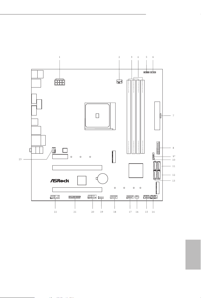
1.3 Motherboard Layout
ATXP WR 1
Sup er
I/O
CLRCMOS1
1
PCI E2
1
USB_2_3
HD_AUDI O1
1
CPU_FAN1
Top:
LINE IN
Center :
FRONT
Bottom :
MIC IN
RJ- 45 L AN
USB 2 .0
T: USB1
B: US B2
SOCKE T AM 4
1
COM1
CMO S
Bat tery
ATX12V1
USB 3.1 Gen1
USB31_T C_1
M2_1
Ult ra M .2
PCIe G en3 x4
USB3_3 _4
1
CHA_FAN1
CHA_FAN2
HDLED RESET
PLED PWRBTN
PANEL1
1
RoH S
SPK_PLED 1
1
DDR4 _A1 (64 bit, 288 -pin mod ule )
DDR4 _A2 (64 bit, 288 -pin mod ule )
DDR4 _B1 (64 bit, 288 -pin mod ule )
DDR4 _B2 (64 bit, 288 -pin mod ule )
PCI E1
PCI E3
M2_2
M2_2_CT 2M2_2_CT 3M 2_2_CT4 M2_2_CT 1
AMD
Pro mont ory
X37 0 /
B35 0 / A 320
PS2
Keybo ard
PS2
Mouse
USB 3. 1 Gen1
T:U SB2
B: USB 3
USB 3. 1 Gen1
T:U SB4
B: USB 5
RGB_HEADE R1
1
AMD_FAN_LE D1
1
USB_5
1
M2_1_CT 3M2_1_CT 2M 2_1_CT1
1
USB_2_4
TPMS1
1
SATA3_3
SATA3_4
SATA3_1
SATA3_2
HDMI 1
DVI1
VGA1
X370M Pro4 R2.0
AB350M Pro4 R2.0
A320M Pro4 R2.0
BIOS
ROM
English
7

No. Description
1 ATX 12V Power Connector (ATX12V1)
2 CPU Fan Connector (CPU_FAN1)
3 2 x 288-pin DDR4 DIMM Slots (DDR4_A1, DDR4_B1)
4 2 x 288-pin DDR4 DIMM Slots (DDR4_A2, DDR4_B2)
5 RGB LED Header (RGB_HEADER1)
6 AMD Fan LED Header (AMD_FAN_LED1)
7 ATX Power Connector (ATXPWR1)
8 USB 3.1 Gen1 Header (USB3_3_4)
9* AMD LED Fan USB Header (USB_5) (for X370M Pro4 R2.0 / AB350M Pro4 R 2.0 only)
10 SATA3 Connector (SATA3_3)
11 SATA3 Connector (SATA3_4)
12 SATA3 Connector (SATA3_2)
13 SATA3 Connector (SATA3_1)
14 System Panel Header (PANEL1)
15 Power LED and Speaker Header (SPK_PLED1)
16 Chassis Fan Connector (CHA_FAN2)
17 USB 2.0 Header (USB_2 _3)
18 USB 2.0 Header (USB_2 _4)
19 Clear CMOS Jumper (CLRCMOS1)
20 COM Port Header (COM1)
21 TPM Header (TPMS1)
22 Front Panel Audio Header (HD_ AUDIO1)
23 Chassis Fan Connector (CHA _FAN1)
English
8
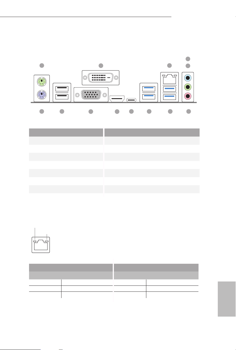
1.4 I/O Panel
1
X370M Pro4 R2.0
AB350M Pro4 R2.0
A320M Pro4 R2.0
4
2
3
5
11
No. Description No. Description
1 PS/2 Mouse Port 8 USB 3.1 Gen1 Ports (USB3_23)
2 DVI-D Port 9 USB 3.1 Gen1 Type-C Port (USB31_TC_1)
3 LAN RJ-45 Port* 10 HDMI Port
4 Line In (Light Blue)** 11 D-Sub Port
5 Front Speaker (Lime)** 12 USB 2.0 Ports (USB_1_2)
6 Microphone (Pink)** 13 PS/2 Keyboard Port
7 USB 3.1 Gen1 Ports (USB3_45)
* ere are two LEDs on each LAN port. Please refer to the table below for the LAN port LED indications .
ACT/LINK L ED
SPEED LE D
LAN Por t
Activity / Link LED Speed LED
Status Description Status Description
O No Link O 10Mbps connection
Blinking Data Activity Orange 100Mbps connection
On Link Green 1Gbps connection
10
8 7913 12
6
English
9
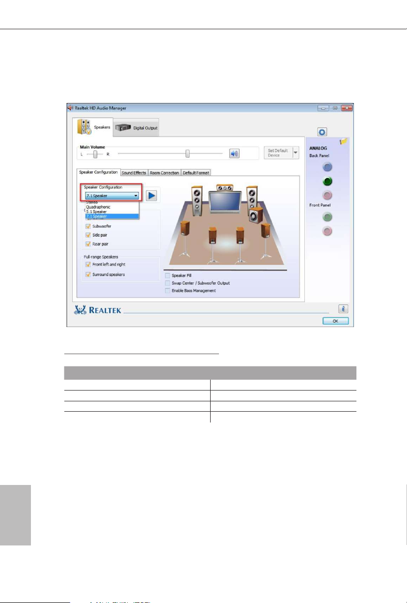
** To congure 7.1 CH HD Audio, it i s required to use an HD front panel audio module and enable the multichannel audio feature through the audio driver.
Please set Speaker Conguration to “7.1 Speaker”in the Realtek HD Audio Manager.
Function of the Audio Por ts in 7.1-channel Con guration:
English
10
Port Function
Light Blue (Rear panel) Rear Speaker Out
Lime (Rear panel) Front Speaker Out
Pink (Rear panel) Central /Subwoofer Speaker Out
Lime (Front panel) Side Speaker Out

X370M Pro4 R2.0
AB350M Pro4 R2.0
A320M Pro4 R2.0
Chapter 2 Installation
is is a Micro ATX form factor motherboard. Before you install the motherboard,
study the conguration of your chassis to ensure that the motherboard ts into it.
Pre-installation Precautions
Take note of the following precautions before you install motherboard components
or change any motherboard settings.
Make sure to unplug the power cord before installing or removing the motherboard.
•
Failure to do so may cause physical injuries to you and damages to motherboard
components.
In order to avoid damage from static electricity to the motherboard’s components,
•
NEVER place your motherboard directly on a carpet. Also remember to use a grounded
wrist strap or touch a safety grounded object before you handle the components.
Hold components by the edges and do not touch the ICs.
•
Whenever you uninstall any components, place them on a grounded anti-static pad or
•
in the bag that comes with the components.
When placing screws to secure the motherboard to the chassis, please do not over-
•
tighten the screws! Doing so may damage the motherboard.
11
English
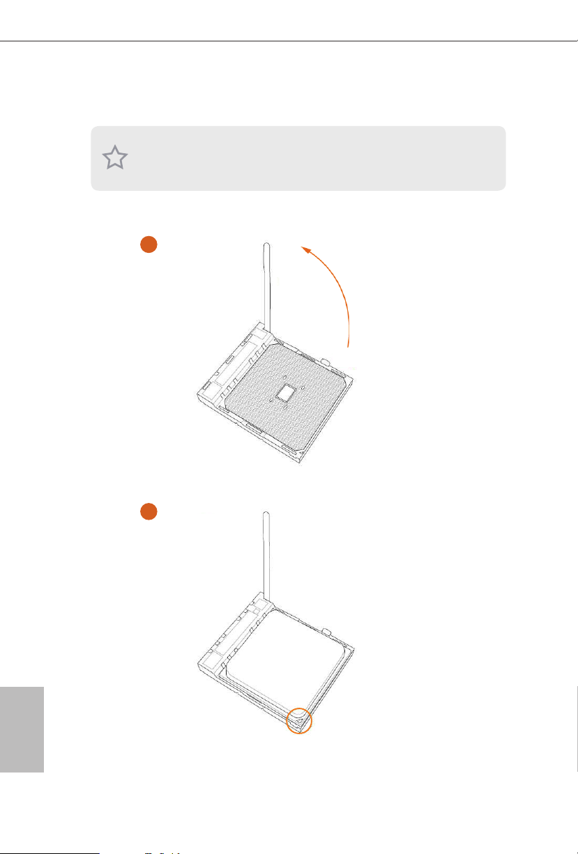
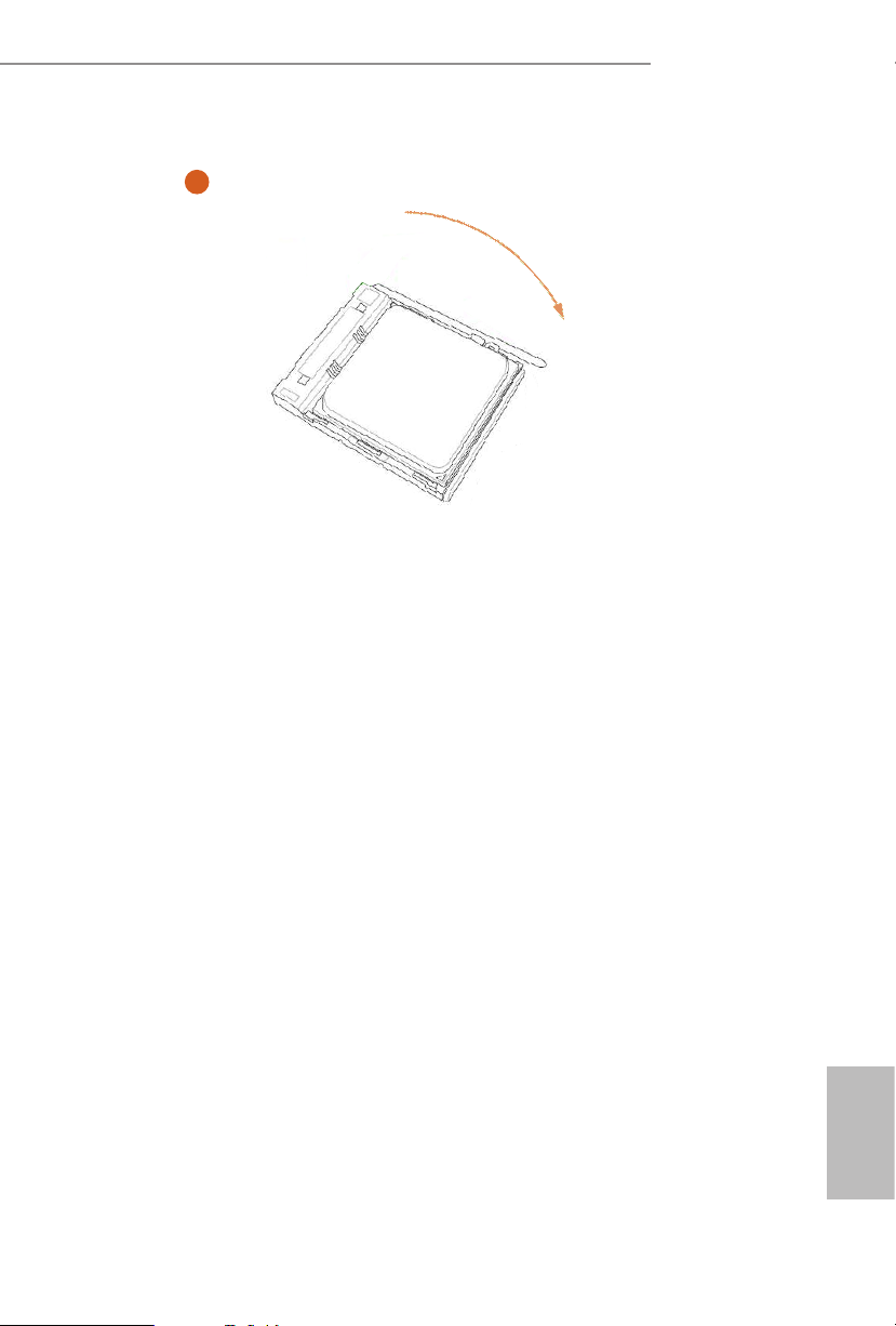
2.1 Installing the CPU
Unplug all power cables be fore installing the CPU.
1
English
12
2
X370M Pro4 R2.0
AB350M Pro4 R2.0
A320M Pro4 R2.0
3
13
English
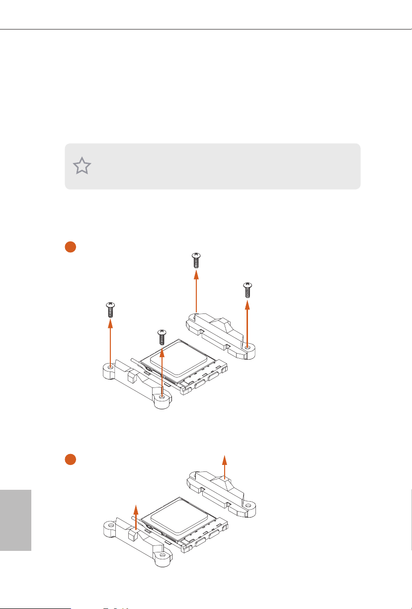
2.2 Installing the CPU Fan and Heatsink
Aer you install the CPU into this motherboard, it is necessary to install a larger
heatsink and cooling fan to dissipate heat. You also need to spray thermal grease
between the CPU and the heatsink to improve heat dissipation. Ma ke sure that the
CPU and the heatsink are securely fastened and in good contact with each other.
Please turn o the power or remove the power cord before changing a CPU or heatsink.
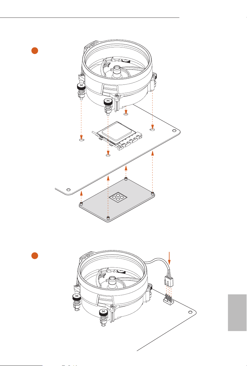
Installing the CPU Box Cooler SR1
1
English
14
2
X370M Pro4 R2.0
AB350M Pro4 R2.0
A320M Pro4 R2.0
3
4
1
N
FA
_
U
P
C
English
15
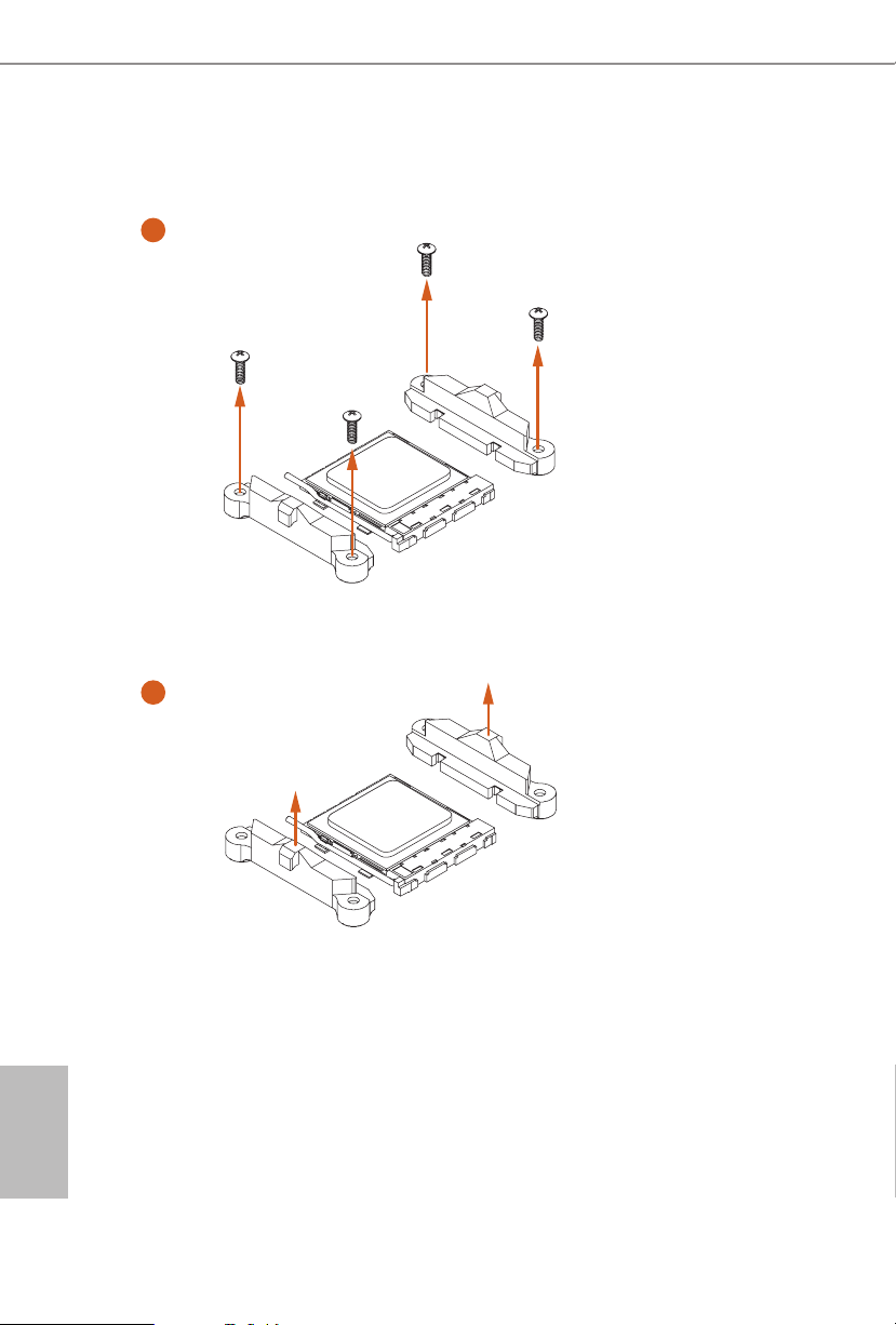
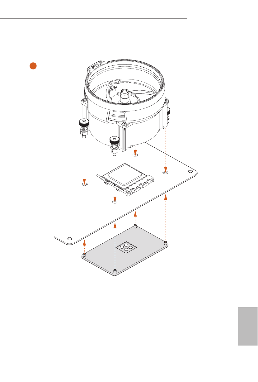
Installing the AM4 Box Cooler SR2
1
2
English
16
X370M Pro4 R2.0
AB350M Pro4 R2.0
A320M Pro4 R2.0
3
17
English
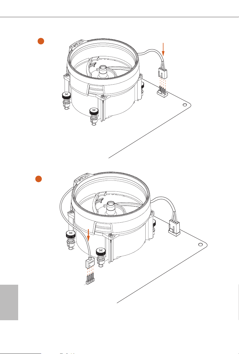
4
1
N
FA
_
U
P
C
5
4-pin FAN cable
English
18
RGB LED Cable
1
N
FA
CPU_
1
D
E
L
_
N
FA
_
D
AM
+12V
*e diagram shown here are for reference only. Please refer to page 32 for the orientation of
AMD Fan LED Header (AMD_FAN_LED1).
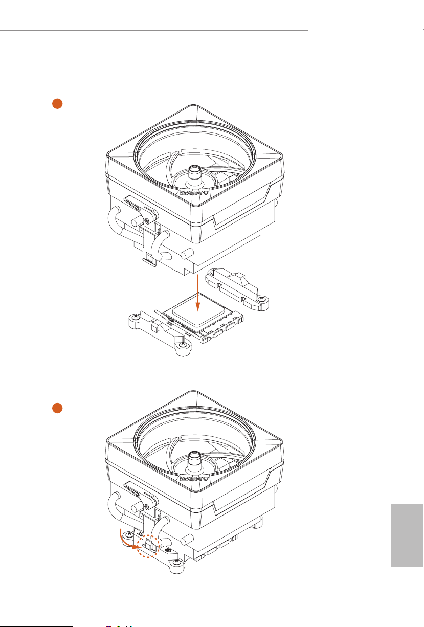
Installing the AM4 Box Cooler SR3
1
X370M Pro4 R2.0
AB350M Pro4 R2.0
A320M Pro4 R2.0
2
English
19
Loading...